ECE 35 Spring 2017
Homework #8 Solution
All homework problems come from the textbook, “Introduction to Electric Circuits”, by Svoboda & Dorf, 9th Edition. Question numbers in the 8th edition are listed for reference.
Question Number Svoboda & Dorf, 8th Edition Svoboda & Dorf, 9th Edition
1 N/A P10.3-2
2 N/A P10.3-4
3 N/A P10.3-6
4 P 10.6-8 P 10.3-8
5 N/A P 10.4-1
6 N/A P 10.4-4
7 P 10.6-7 P 10.4-9
8 P 10.6-1 P 10.4-11
9 N/A P 10.5-2
10 P 10.7-1 P 10.5-10
11 P 10.8-10 P 10.5-17
12 P 10.8-16 P 10.5-23
P 10.3-2 Express the voltage v t
5 2 cos 8
t 2sin 8
t 45 V
In the general form v t
Acos
t
V where A0 and 180 180.Solution:
5 2 cos 8 2 sin 8 45
5 2 cos 8 2 cos 8 45 90 5 2 cos 8 2 cos 8 45 V
v t t t
t t t t
Representing the sinusoids using phasors gives:
𝑽 = 5√2 ∠0° + 2 ∠ − 45° = 5√2 + (√2 − 𝒋√2) = 6√2 − 𝒋√2
𝑽 = √(6√2)2+ (−√2)2 ∠ tan−1(−1
6) = 8.602 ∠ − 9.46°
The corresponding sinusoid is: 𝑣(𝑡) = 8.602 cos(8𝑡 − 9.46°) (𝑉)
P 10.3-4 Determine the polar and rectangular form of the expression
3 2 45
5 81.87 4 3
7 1
j
j
Solution:
5 ∠81.87° (4 − 𝑗3 +3√2 ∠ − 45°
7 − 𝑗1 )
= ( 5 ∠81.87° ) (4 − 𝑗3 + 3√2 ∠ − 45°
5√2 ∠ − 8.13°)
= ( 5 ∠81.87° ) ( 4 − 𝑗3 + 0.6 ∠ − 36.87° ) = ( 5 ∠81.87° ) ( 5 ∠ − 36.87° + 0.6 ∠ − 36.87° ) = ( 5 ∠81.87° ) ( 5.6 ∠ − 36.87° )
P 10.3-6 The circuit shown in Figure 10.3-6 is at steady state. The input currents are
1 10 cos 25 mA
i t t and i3
t 10 cos 25
t135
mADetermine the voltage v2(t).
Figure 10.3-6
Solution:
Using first Ohm’s law and then KCL
2 250 2
v t i t
and i2
t i t1
i3
t 10 cos 25
t
10 cos 25
t135
mAUsing phasors
2 1 3 10 10 135 10 7.071 7.071 mA
17.071 7.071 18.478 22.5 mA
j j
I I I
The corresponding sinusoid is i2
t 18.478 cos 25
t22.5
mAP 10.3-8 Given that
i1(t) = 30 cos (4t + 45°) mA
and i2(t) = – 40 cos (4t) mA
Determine v(t) for the circuit shown in Figure P 10.3-8.
Figure P 10.3-8 Solution:
4 15
1 2
60 0.03 45
0.04 0
60 0.0212
0.0212 0.04
1.273 1.127
1.7 138.5 V
j j j j
j
V I I
So v t
1.7 cos 4
t138.5
VP 10.4-4 Represent the circuit shown in Figure P10.4-4 in the frequency domain using impedances and phasors.
Figure P10.4-4
P 10.4-1 Figure P10.4-1a shows a circuit represented in the time domain. Figure P10.4-1b shows the same circuit represented in the frequency domain, using phasors and impedances. ZR, ZC, ZL1,
and ZL2 are the impedances corresponding to the resistor, capacitor, and two inductors i n Figure
P10.4-1a. Vs is the phasor corresponding to the voltage of the voltage source. Determine ZR, ZC,
ZL1, ZL2, and Vs.
Figure P10.4-1 Hint: 5 sin 5t = 5 cos (5t – 90°)
Answer: R 8 , C 1 2.4 2.4 2.4 , L1 5(2) 10 ,
1 5
12
j
j j j
j j j j
Z Z Z
ZL2 = j5(4) = j20 Ω, and Vs = 5 –90° V
Solution: ZR = 8 , ZC = , ZL1 = j 5 (2) = j 10 ,
ZL2 = j 5 (4) = j 20 and VS = 5 -90 V.
1 2.4 2.4
2.4 1
5 12
j
j
j j j
j
P 10.4-9 This voltage and current for the circuit shown in Figure P10.4-9 are given by
20 cos (20 15 ) Vv t t and i t
1.49 cos (20t 63 ) ADetermine the values of the resistance, R, and capacitance, C.
Figure P10.4-9
Solution:
1 20 15 20
15 63 13.42 48 8.98 9.97
20 1.49 63 1.49
R j j
C
V Z
I
Equating real and imaginary parts gives R = 9 and 1 5 mF 20 9.97
C
.
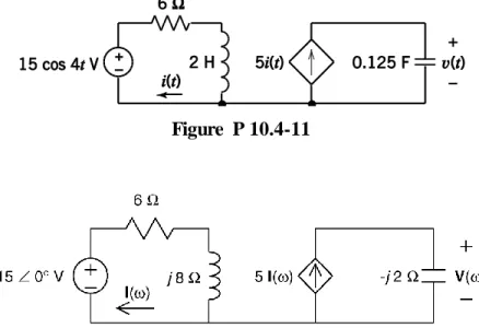
P 10.4-11 Represent the circuit shown in Figure P 10.4-11 in the frequency domain using impedances and phasors.
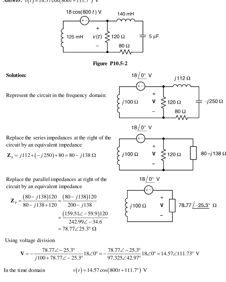
P 10.5-2 Determine the voltage v(t) in the circuit shown in Figure P10.5-2. Answer: v t
14.57 cos 800
t111.7
VFigure P10.5-2
Solution:
Represent the circuit in the frequency domain:
Replace the series impedances at the right of the circuit by an equivalent impedance
S j112 j250 8080 j138 Z
Replace the parallel impedances at right of the circuit by an equivalent impedance
P
80 138 120 80 138 120
80 138 120 200 138
159.51 59.9 120
242.99 34.6
78.77 25.3
j j
j j
Z
Using voltage division
78.77 25.3 78.77 25.3
18 0 18 0 14.57 111.73 V
100 78.77 25.3 97.325 42.97
j
V
P 10.5-10 Find Z and Y for the circuit of Figure P 10.5-10 operating at 10 kHz.
Figure P 10.5-10 Solution:
3
2 f 2 (10 10 ) 62832 rad sec
R R
R
1 1
36 0.0278 S
36 R Z Y Z 6 L L L 1
(62830)(160 10 ) 10.053 10 0.1 S
j L j j j j
Z Y
Z
C 6 C
C 1
15.915 16 0.0625 S
(62830)(1 10 )
j j
j j j
C Z Y Z
eq R L C 0.0278j0.03750.0467 53.4 S
Y Y Y Y
eq eq
1
21.43 53.4 12.75 17.22 j
P 10.5-17 Determine the steady-state voltage, v(t), and current, i(t), for each of the circuits shown in Figure P 10.5-17.
Figure P 10.5-17
Solution:
(a)
4
24 8 V
4 40 10
40 24 8
1.6 A
40 10 4 40 10 5
v t
i t
(b) Represent the circuit in the frequency domain using impedances and phasors.
16
24 15
16 90
24 15
33.66 65 V40 25
16 40 25
16
40 25
j
j
j j
j
j
V
40 24 15
1.78 57 A
40 25
40 25
16
40 25
j j
j
j
I
so
33.66 cos 4
65
Vv t t
and
1.78 cos 4
57
AP 10.5-23 Determine the steady state current i(t) for this circuit:
Solution:
Represent the circuit in the frequency domain using impedances and phasors. Let
1
2
3
1
25 20 2 25 15 29.2 31
20 0.002
1
20 20 10 22.36 26.6
20 0.005
40 20 2 40 40 56.57 45
j j
j
j j
j j
Z
Z
Z
and let
p 2 3 18.86 8 18.67 j2.67
Z Z Z
Then
2
1 p 2 3
16 75
0.118 6.1 A
Z I
Z Z Z Z
so
0.118 cos 20
6.1
AP 10.5-30 Determine the steady state voltage, v(t), for this circuit:
Solution:
15 681
8 6
4 19.2 V
8 6
j j
j
e e
j
V
15 752
12 4
4 24 V
12 4
j j
j j
e e
j j
V
221 2 14.4 V
j
e