Interfacing with C++
Programming Real-World Applications
Library of Congress Control Number:2005937895
ISBN-10 3-540-25378-5Springer Berlin Heidelberg New York ISBN-13 978-3-540-25378-5Springer Berlin Heidelberg New York
This work is subject to copyright. All rights are reserved, whether the whole or part of the material is concerned, specifically the rights of translation, reprinting, reuse of illustrations, recitation, broadcasting, reproduction on mi-crofilm or in any other way, and storage in data banks. Duplication of this publication or parts thereof is permitted only under the provisions of the German Copyright Law of September9,1965, in its current version, and permission for use must always be obtained from Springer. Violations are liable for prosecution under the German Copyright Law.
Springer is a part of Springer Science+Business Media springer.com
c
Springer-Verlag Berlin Heidelberg2006 Printed in The Netherlands
The use of general descriptive names, registered names, trademarks, etc. in this publication does not imply, even in the absence of a specific statement, that such names are exempt from the relevant protective laws and regulations and therefore free for general use.
Typesetting: by the authors and TechBooks using a Springer LATEX macro package Cover design:design & productionGmbH, Heidelberg
Printed on acid-free paper SPIN:11015543 89/TechBooks 5 4 3 2 1 0
Manufacturing Engineering The University of New South Wales Sydney NSW2052, Australia Email: [email protected]
1 GETTING STARTED ...1
1.1 INTRODUCTION...2
1.2 PROGRAMDEVELOPMENTSOFTWARE...2
1.3 A C++ PROGRAM...6
1.4 USE OF FUNCTIONS...10
1.5 FUNDAMENTALDATATYPES...15
1.6 FUNCTIONS WITH PARAMETERS AND RETURNVALUES...18
1.7 SUMMARY...21
1.8 BIBLIOGRAPHY...22
2 PARALLEL PORT BASICS AND INTERFACING ...23
2.1 INTRODUCTION...24
2.2 WHAT IS THE PARALLELPORT? ...24
2.3 DATAREPRESENTATION...30
2.4 PROGRAMDEMONSTRATINGHEXADECIMAL TO DECIMAL...32
2.5 SUMMARY...33
2.6 BIBLIOGRAPHY...33
3 TESTING THE PARALLEL PORT...35
3.1 INTRODUCTION...36
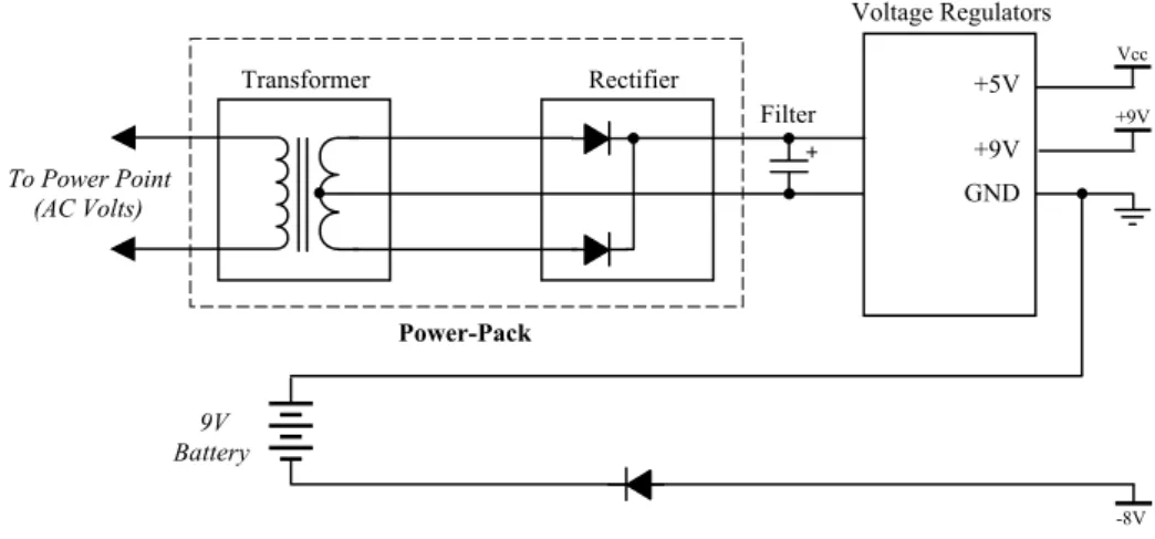
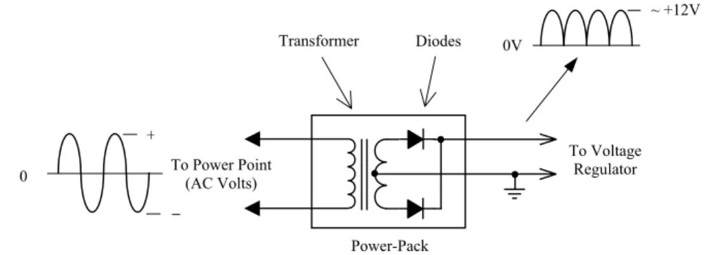
3.2 INTERFACEBOARDPOWERSUPPLY...36
3.3 PARALLELPORTINTERFACE...39
3.4 BASICOUTPUTUSING THE PARALLELPORT...43
3.5 BASICINPUTUSING THE PARALLELPORT...46
3.6 COMPENSATING FOR INTERNALINVERSIONS...50
3.7 SUMMARY...55
3.8 BIBLIOGRAPHY...56
4 THE OBJECT-ORIENTED APPROACH...57
4.1 INTRODUCTION...58
4.2 CONCEPTUAL AND PHYSICALLYREALISABLEOBJECTS...58
4.3 REAL OBJECTS...59
4.4 OBJECTCLASSES...61
4.5 ENCAPSULATION...63
4.6 ABSTRACTCLASSES...64
4.7 CLASSHIERARCHIES...64
4.8 INHERITANCE...65
4.9 MULTIPLEINHERITANCE...66
4.10 POLYMORPHISM...66
4.11 ANEXAMPLEOBJECTHIERARCHY...67
4.12 ADVANTAGES OF OBJECT-ORIENTEDPROGRAMMING...72
4.13 DISADVANTAGES OF OBJECT-ORIENTEDPROGRAMMING...72
4.15 BIBLIOGRAPHY...73
5 OBJECT-ORIENTED PROGRAMMING...75
5.1 INTRODUCTION...76
5.2 NAMINGCONVENTION...76
5.3 DEVELOPING AN OBJECTCLASS...77
5.4 PARALLELPORTCLASS– STAGEI...82
5.5 USINGCLASSOBJECTS IN PROGRAMS...87
5.6 PARALLELPORTCLASS– STAGEII ...94
5.7 PARALLELPORTCLASS– STAGEIII...99
5.8 SUMMARY...103
5.9 BIBLIOGRAPHY...103
6 DIGITAL-TO-ANALOG CONVERSION ...105
6.1 INTRODUCTION...106
6.2 DIGITAL-TO-ANALOGCONVERSION...106
6.3 PROGRAMMING THE DIGITAL-TO-ANALOG CONVERTER...117
6.4 DERIVATION OF OBJECTCLASSES...121
6.5 ADDINGMEMBERS TO DERIVEDCLASSES...129
6.6 SUMMARY...145
6.7 BIBLIOGRAPHY...146
7 DRIVING LEDS ...147
7.1 INTRODUCTION...148
7.2 ITERATIVE LOOPS...148
7.3 BRANCHING...152
7.4 ARRAYS...157
7.5 POINTERS...160
7.6 USINGPOINTERS...175
7.7 MACROS...184
7.8 DYNAMICMEMORYALLOCATION...185
7.9 EXCEPTIONHANDLING...189
7.10 SUMMARY...194
7.11 BIBLIOGRAPHY...195
8 DRIVING MOTORS - DC & STEPPER...197
8.1 INTRODUCTION...198
8.2 DC MOTORS...198
8.3 STEPPERMOTORS...202
8.4 A CLASSHIERARCHY FOR MOTORS...211
8.5 VIRTUALFUNCTIONS– ANINTRODUCTION...212
8.6 VIRTUALFUNCTIONS- APPLICATION...233
8.7 KEYBOARD CONTROLS...256
8.8 SUMMARY...270
9.1 INTRODUCTION...274
9.2 EFFICIENTCODINGTECHNIQUES...274
9.3 MODULAR PROGRAMS...282
9.4 CASESTUDY- MOTORDRIVERPROGRAM...289
9.5 SUMMARY...302
9.6 BIBLIOGRAPHY...302
10 ...303
10.1 INTRODUCTION...304
10.2 CONVERTING A VOLTAGE TO A DIGITAL PULSE-TRAIN...304
10.3 TEMPERATUREMEASUREMENT...305
10.4 THEOBJECTCLASSVCO...306
10.5 MEASURINGVOLTAGESUSING THE VCO ...311
10.6 GRAPHICSPROGRAMMING– SQUAREWAVEDISPLAY...318
10.7 TEMPERATUREMEASUREMENT...324
10.8 SUMMARY...328
10.9 BIBLIOGRAPHY...329
11 ...331
11.1 INTRODUCTION...332
11.2 ANALOG-TO-DIGITALCONVERSION...332
11.3 CONVERSION TECHNIQUES...334
11.4 MEASURINGVOLTAGES WITH AN ADC...341
11.5 ANOBJECTCLASS FOR THE ADC ...347
11.6 MEASURINGVOLTAGEUSING THE ADC ...356
11.7 MEASURINGTEMPERATUREUSING THE ADC...359
11.8 SUMMARY...362
11.9 BIBLIOGRAPHY...362
12 ...363
12.1 INTRODUCTION...364
12.2 OPERATOROVERLOADING...364
12.3 DATAACQUISITION...393
12.4 SUMMARY...397
12.5 BIBLIOGRAPHY...397
13 ...399
13.1 INTRODUCTION...400
13.2 PC TIMERSYSTEM...400
13.3 PROGRAMMING THE TIMER...408
13.4 THEOBJECTCLASSPCTIMER...409
13.5 MEASUREMENT OF TIME...415
13.6 REFLEXMEASUREMENT...417
13.7 GENERATING A TIME-BASE...419
13.8 DATAACQUISITION WITH TIMESTAMP...423
13.9 SUMMARY...430
13.10 BIBLIOGRAPHY...430
9 PROGRAM DEVELOPMENT TECHNIQUES...273
VOLTAGE AND TEMPERATURE MEASUREMENT....
ANALOG-TO-DIGITAL CONVERSION...
DATA ACQUISITION WITH OPERATOR OVERLOADING....
APPENDIX A - HARDWARE...431
CIRCUITCONSTRUCTION...432
INTERFACEBOARDBILL OF MATERIALS...476
APPENDIX B - SOFTWARE ...479
C++ KEYWORDS...480
OPERATORPRECEDENCE...481
ASCII CHARACTERSET...482
C++ is considered by many to be among the most widely used and powerful object-oriented programming language in industry today. This book is for people who are interested in learning and exploring C++ programming in a fresh and enjoyable environment where programs are developed to interface with real world devices. Other people may leave learning C++ for a later time, instead choosing to interact with various hardware devices by simply running the fully developed programs supplied with this book.
Many readers may already have acquired some knowledge of C++ programming but know little about how to interface a computer to physical devices and want to know more. You might be an engineer, scientist, programmer, technical personnel, hobbyist, student in a technically related field or someone who is simply interested in programming and interfacing a computer to perform real activities.
Inside This Book…
C++ programming is approached in a straightforward, practical and simplified manner using mostly short programs that are clearly explained. You will explore areas of electronics integral to a wide range of modern technologies using an interface board specially developed to support all projects described in this book. The intertwining of C++ programming and electronics knowledge takes place as we work through interesting and enjoyable real-world projects. These projects encompass the following topics:
x Digital Input and Output.
x Analog-to-Digital Conversion and Digital-to-Analog Conversion. x DC Motor and Stepper Motor Control.
x Measuring Voltage, Temperature, and Time.
Important concepts are reinforced during the learning and exploration process as we gradually progress from simple straightforward projects to those that are more advanced. Projects on the interface board have been developed as independent modules. This allows readers with C++ programming knowledge to build and play with whichever projects they wish, in any order.
What is C++?
C++ is a language used to program computers to perform specific tasks. There exist many other popular programming languages including C, Pascal, FORTRAN, BASIC, Cobol and Modula II. Computers operate using instructions based on binary format, i.e. on and off states (or ones and zeros). Programming languages allow the programmer to use a language similar to that normally written and then generate computer-based instructions for program execution. Specialised software is used to manage the task of developing programs; in particular converting the program written in its programming language to binary form needed by the computer.
In the recent past the language known as C became very popular and was the most significant commercially used programming language. The C language was developed in response to the need for a good programming language to develop the UNIX operating system. While it is considered a high-level language, it also has many low-level features. This is of great benefit when programs need to work with hardware. On the other hand it was also well suited to performing numerical operations. It can match the capabilities of FORTRAN and Pascal (a language able to handle complex logic). These are some of the reasons for the popularity of the C language.
Most programs in this book have been written to carry out some form of interfacing task. An essential feature of such programs is
operating systems such as DOS, Windows 3.1, Windows 95/98 allow programs to directly access ports. Other operating systems
such as Windows NT/2000/XP and Linux do not allow direct port access. These operating systems will only allow programs to access ports via a piece of software
known as a device driver that has the necessary privileges to access ports. The application programs access the ports via the device drivers.
Borland C++ for DOS
Apart from the programs using exception handling (See Chapter 7), all programs in the textbook can be compiled and linked using Borland C++ without any changes to generate executable files. All program listings that are to be compiled using Borland C++ are located in the directory ‘BC++’ on the companion CD.
GNU C++ for Linux
The programs in the textbook have been modified to request the required privileges to enable them to run under Linux with port access. The modified versions of programs can be found in the directory ‘GNUC++’ of the companion CD. If a make file is necessary, it is also included in the appropriate chapter subdirectories of the directory GNUC++. Graphics programs, keyboard control programs and PC timer related programs are not available to run under Linux.
Microsoft Visual C++ for Windows
The modified versions of the programs that can be used with Microsoft® Visual C++ can be found in the directory ‘VC++’ on the companion CD. The programs in the ‘Win98’ subdirectory can be run under Windows98 without the need of a device driver. The programs in the ‘Windows’ subdirectory can be run under Windows NT/2000/XP with the use of WinIO, which will act as the driver. These programs have been modified to enable them to access the ports through the use of WinIO. WinIO has not been included in the accompanying CD. Its latest version can be downloaded from http://www.internals.com/. You must first install WinIO in order to be able to run the programs in the ‘Windows’ subdirectory. The readers of this book who use WinIO are bound by the WinIO licensing agreement published on the web. Graphics programs, keyboard control programs and PC timer related programs are not available to run under Microsoft® Windows.
Getting Started
Inside this Chapter
x
Developing programs – what is involved?x
Writing and running your first C++ program.x
Program syntax.x
Functions.The aim of this chapter is to get you started in writing C++ programs. We will develop a number of simple C++ programs and learn the syntax and typography associated with writing a program. One of the basic building blocks of any C++ program is the so-called function. This chapter will explain the basic concepts behind C++ functions and their use. The C++ language has built-in fundamental data types that can be used to develop complex user-written data types. Some of the fundamental data types will be explained in this chapter.
Towards the end of the chapter we will step through the complete program development process; starting from planning a small program down to using the elements of program development software needed to generate a program that can be run on your computer. We will commence with the use of non-object-oriented programming methods because these programs are simpler to understand at this early stage. Object-oriented programming concepts will be explained in Chapter 4 and then used extensively through the remainder of the text.
1.2 Program Development Software
The process of program development includes a number of subtasks. To be able to develop a program you must have an editor, a compiler and a linker. In modern program development platforms, these subtasks are seamlessly integrated and the entire process is very transparent. Such platforms are known as Integrated Development Environments (IDEs). Most modern C++ packages (the software that you will use to develop C++ programs) provide some sort of an IDE. Some of the commercially available packages include Turbo C++, Borland C++, C++ Builder and Visual C++. There are also packages referred to as command line versions. The command line versions require you to type a command (say at the DOS prompt) to invoke the editor. Then you must use another command line to invoke the compiler and so forth.
Along with the editor, compiler and linker, these packages also provide extensive library support. Sometimes these libraries are referred to as run-time libraries (RTLs). They contain a wide variety of routines or functions we can use within our programs. Regardless of what package we use, it is worthwhile to understand what happens during each subtask. The following sections will describe editing, pre-processing,compiling, and linking.
1.2.1 Editing
contents of the editor into a file. The two editors mentioned above will only store what you type. They will not add extra characters to your file (unlike some editors). What we normally type includes digits, letters, punctuation marks, the space, tab, carriage return and line-feed characters. The line-feed character is used by the editor to position the cursor on a new line. The carriage return character is used by the editor to position the cursor at the start of the next line. A program file must not contain characters apart from those listed above. The file that contains all programming instructions, is known as the source file. The source file is said to contain the source code, which is nothing more than the programming instructions you typed.
1.2.2 Compiling
The second step is to compile the source file. For this purpose, a special program known as a compiler is used. As part of the compiler, a program named the
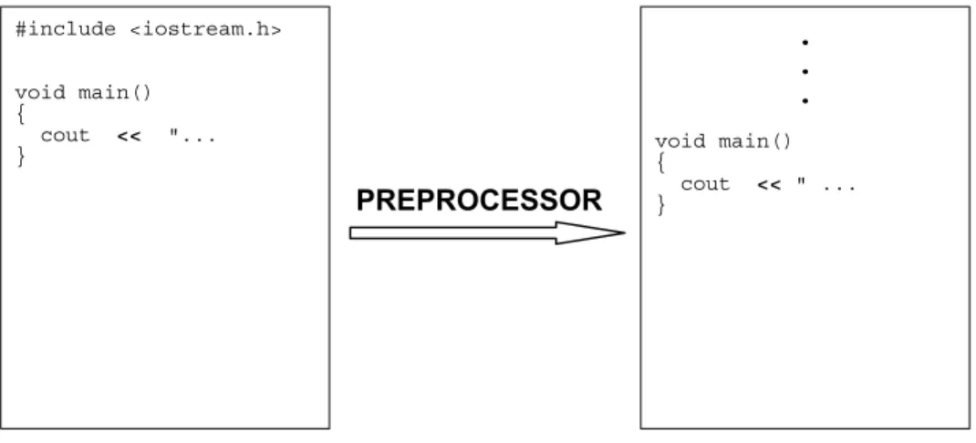
preprocessor is invoked. This takes place before the actual compilation of your source code. The preprocessor attends to your source code statements that start with the '#' sign. (See the program listings ahead for the lines starting with a ‘#’ sign). These statements are referred to as compiler directives. The preprocessor takes action as directed by these statements and will modify your original source file. At the end of preprocessing, all lines starting with the '#' sign will have been processed and eliminated. This process is shown in Figure 1-1. The preprocessor and the compiler are gradually becoming merged - most modern compilers have the preprocessor as a built-in part of the compiler itself.
Figure 1-1 Preprocessor attends to all lines starting with '#' symbol.
The compiler in-turn processes the file produced by the preprocessor and produces a file known as an object file. The object file contains what is known as object code, which the Central Processing Unit (CPU) of your computer understands, also known as machine code. However, the PC cannot execute the object code since it
#include <iostream.h>
void main() {
cout << "... }
. . .
void main() {
cout << " ... }
still has a few parts missing. At this stage your program is in a similar state to an unfinished highway with some stretches complete and others not. As a result, the compiled program cannot yet be executed (i.e. run on your computer).
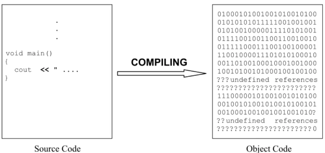
At this incomplete stage, the object code is said to contain undefined references. The undefined references refer to pieces of object code that need to be retrieved from elsewhere to complete the entire program. Just like the highway, the object file does not have a continuous execution path. The compiling process is shown in Figure 1-2.
Figure 1-2 The compiler converts the source code to object code.
The syntax used as part of the program statements is extremely important. As mentioned earlier, syntax refers to the use of punctuation marks within the source file. Most of the time these punctuation marks act as delimiters. A delimiter identifies the end of variables, keywords, numbers, statements etc. The space, the comma, the semicolon, the colon, the brace etc., act as delimiters for different contexts of usage. Compilers have limited in-built intelligence. If you miss a semicolon the compiler will detect it and report an error, but it cannot correct the error for you.
As mentioned earlier, the object code is incomplete with many unresolved areas and it cannot be executed. For example, the object code may contain calls to various routines. The object file includes function calls to be made. The actual instructions to be executed during the call are not yet in place. These instructions may be available elsewhere in the object file, or they may need to come from a library file or another object file. Note that finding the missing bits is not part of the compiler’s duties – the compiler can be viewed in basic terms as a translator that checks grammatical content!
Source Code
. . .
void main() {
cout << " .... }
01000101001001010010100 01010101011111001001001 01010010000011110101001 01111001001100110010010 01111100011100100100001 11001000011101010100010 00110100100010001001000 10010100101000100100100 ???undefined references ??????????????????????? 11100000101001001010100 00100101001010010100101 0010001001001001001010? ??undefined references ??????????????????????0
Object Code
1.2.3 Linking
The program that bridges all the gaps and completes assembly of the program is known as the linker. It will search all the object files and the libraries to find the missing sets of instructions. Sometimes the linker must be told to search certain libraries and object files. These are either third party libraries you may have purchased or the libraries and object files you developed. The linker automatically searches the libraries and object files that come with the C++ software, one being the so-called Run-Time Library (RTL). The linker will insert the missing sets of instructions into appropriate places to form a file that has a ‘gaps free’ execution path. This process is known as linking. At the end of the linking process, we have a file the PC can execute, known as an executable file.
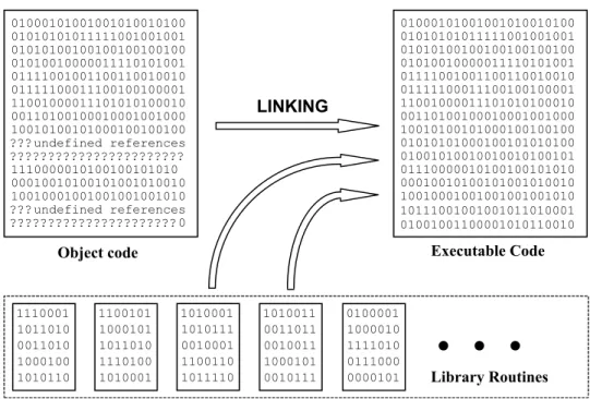
The program must be loaded into the computer's memory before execution can begin. This action is carried out by a piece of executable code known as a loader. Most linkers append a loader to the start of the executable file. Therefore, when we try to run the program, first the loader will run, loading the program into memory and then actual program execution will begin. Figure 1-3 shows the linking process.
Figure 1-3 Linking forms a gaps-free executable code.
01000101001001010010100 01010101011111001001001 01010100100100100100100 01010010000011110101001 01111001001100110010010 01111100011100100100001 11001000011101010100010 00110100100010001001000 10010100101000100100100 ???undefined references ??????????????????????? 1110000010100100101010 00010010100101001010010 10010001001001001001010 ???undefined references 01000101001001010010100 01010101011111001001001 01010100100100100100100 01010010000011110101001 01111001001100110010010 01111100011100100100001 11001000011101010100010 00110100100010001001000 10010100101000100100100 01010101000100101010100 01001010010010010100101 01110000010100100101010 00010010100101001010010 10010001001001001001010 Library Routines
Object code Executable Code
LINKING 1110001 1011010 0011010 1000100 1010110 1110001 1011010 0011010 1000100 1010110 1100101 1000101 1011010 1110100 1010001 1010001 1010111 0010001 1100110 1011110 1010011 0011011 0010011 1000101 0010111 0100001 1000010 1111010 0111000
0000101 Library Routines
1.3 A C++ Program
A computer sees a program as a set of instructions to be executed. The programmer arranges these instructions in a certain order depending on the tasks the computer is expected to perform. To give you a simple example; if you want to write a program to add two numbers, the numbers must be entered first and then the addition must be carried out. Therefore, the instructions to read the numbers must come before the instructions to add the numbers.
Each programming language has its own unique syntax. Syntax is the typography and the use of punctuation marks. Here, we will learn the syntax that applies to the C++ programming language.
As mentioned earlier, the basic building block of a C++ program can be viewed as the function – a procedure that produces an end result. Therefore, every C++ program that contains a set of executable instructions must have a function. One of these functions is special, and is named main. To uniquely identify functions separately from other entities in our text, we use a pair of parentheses () after the function name. Simple programs can be written just with a main() function. When programs become more elaborate and complex, other functions may have to be written in addition to the main() function.
The aim of our first C++ program is to print a text message on the screen of your computer. The lines of this program are given in Listing 1-1.
Listing 1-1 Program to print a text message on the screen.
/* This program prints a text message on your screen. The program consists of just one function named main.*/
#include <iostream.h>
// The main function. void main()
{
cout << “Getting Started “ << endl; }
If you run this program, you will see the message:
Getting Started
1.3.1 Comments in Programs
Comments are descriptions included in a program that are used so programmers can document their work. They often describe a program or specific parts of a program and do not form any part of the actual program’s instructions that will run on the computer. If you include comments, you must indicate to the compiler that they are not to be considered as actual code when the compiler prepares the final program prior to execution. There are two different ways to include comments:
(i) To include single line or multi-line comments you can use ‘/*’ at the start of the comment and ‘*/’ at the end of the comment.
(ii) If the comment is a single line comment you may use ‘//’ at the start of the comment.
In Listing 1-1, we have a multi-line comment and a single line comment. The multi-line comment is:
/* This program prints a text message on your screen The program consists of just one function named main().*/
The single line comment is:
// The main function.
The text contained within ‘/*’ and ‘*/’ will be ignored by the compiler. Likewise for the text after ‘//’ on that line.
1.3.2 Header Files
The first line after the multi-line comment of Listing 1-1 is an include statement:
#include <iostream.h>
It instructs the preprocessor to replace that statement with the entire contents of the file iostream.h. In our program this takes place just before the start of the main() function. The files with the file extension ‘.h’ are known as header files
or as include files. A header file can already exist within the C++ development software, or it may be a file created by the programmer. If it is a file provided with the C++ development software, then it resides in a special sub-directory known as theInclude Directory, as is the case for the iostream.h file. Programs can have more than one include statement, resulting in the inclusion of a number of header files.
change them. If the compiler issues error or mismatch messages, then we must change our program – not the header file.
Library routines are ready-made pieces of software we can make use of. The programmers who write the library routines must also prepare the header files belonging to the library routines. By programming in strict conformance with the header files, we are conforming with the library routines we have used that are associated with those same header files.
In the program shown in Listing 1-1 we have used cout, double left arrows ‘<<’, and endl within our program. They do not form part of the C++ language in the context we have used them. Unless we instruct the compiler as to the usage of these elements, the compiler cannot interpret their proper use. The header file iostream.h contains all the necessary programming statements to inform the compiler how the elements should be used. This information must appear before using cout, << and endl. Hence, the include statement appears before the first use of cout,<< and endl in our program.
The compiler does not need the entire contents of the file iostream.h to be able to translate the program shown in Listing 1-1 into code that the computer understands. In our example, it would be sufficient to show the part of iostream.h that describes cout, endl, and the behaviour of the operator <<. However, it is very difficult to determine exactly which parts of a header file are necessary for a particular program. Therefore, compilers run through the entire header file. The size of the header files will not have any affect on the size of the executable files, although the time to prepare the program will increase slightly. If necessary, we may need to include more than one header file. In addition, there may be other header files used in each of the ones we include.
In conclusion, the appropriate header file must be included first to provide various definitions of constants and data types, and also to declare various functions before using those constants, data types and functions in a program.
1.3.3 Program Syntax
Syntax refers to the use of punctuation marks in the program. In our program, we have used the # symbol, angle brackets (< >), the pair of parentheses, braces ({}), semi-colon and <<. These punctuation marks must be correctly inserted at the appropriate places before the compiler can recognise your program as being error-free. The program in Listing 1-1 shows only basic syntax. As programs become more complex, their syntax also becomes more involved.
All lines starting with a hash symbol (#) are instructions to a special part of program development software named the preprocessor, discussed previously. Our program has just one function – the main() function. The start of the body
line that contains main(). It ends at the closing brace of the main() function’s body.
The syntax of the main() function can be expressed in a compact form as shown:
void main(){statement1; statement2; statement3;}
The function has the name main. The pair of parentheses that follow the name main may or may not be empty - in our simple program they are empty. As can be seen, semi-colons are used to separate the statements of the program. Although it may appear redundant, the semi-colon after the last statement is essential.
1.3.4 Keywords
Keywords are words reserved by the language. They must not be used for purposes other than those specified for them by the C++ language. For example, a keyword cannot be used as an identifier. Identifiers are variable names we create to identify various entities such as functions, user created data types and data. So far, the only keyword we have seen is void. A list of keywords is given in Appendix B.
1.3.5 The Return Value Type
The word void right at the start of our main function describes the return value type of the main() function. Every function, let it be the main() function or some other function, must specify a return value type. The return value can be viewed as the end-product or the output produced by the function. If a function is programmed to return a value, the programmer must specify the data type of the value to be returned (to be issued out). It is also possible to program a function to not return a value. Such functions generally carry out some task but do not produce a value to be issued out. For these functions the return value type is void. This is the case in our program. Note that when no values are returned by a function the keywordvoidmust be used to specify the return value type.
NOTE
If a return value type is not specified for the main() function, the return value type will default to that of an integer. This means the function must produce an integer output.
1.3.6 The Body of
main()
cout << “Getting Started “ << endl;
The use of cout will instruct the computer to stream whatever follows to the standard output device, in this case your screen. Streaming has a definition in the C++ language. For now, it’s sufficient to understand streaming as directing one entity (such as a group of characters, an integer, etc.) after another to a certain destination. First, Getting Started will appear on the screen. Next, endl will be streamed to the screen. The effect of this is to position the cursor at the start of a new line on the screen. Execution of the program is now complete.
You can experiment by replacing the previous statement by:
cout << “Getting Started”;
This will only stream Getting Started to the screen. It will not stream endl to the screen. You will see the cursor blinking at the end of the words ‘Getting Started’.
1.4 Use of Functions
As mentioned earlier, functions form an integral, important part of C++ programming. In this section we will learn how to use a function. As explained earlier, a function can be thought of as a procedure that produces some sort of an end result based on the inputs it receives. Some of the inputs the function will receive are known as parameters or formal arguments. The formal arguments are used at the time of programming a function to indicate the type of arguments it can receive. At the time of executing the function in your computer, the formal arguments must be replaced by actual arguments. For example, at the time of programming, we may use a formal argument named a. At the time of executing the function, the formal argument a must be replaced by an actual argument such as the number 3. The same function can be called (executed) again replacing the formal argument with a different actual argument, producing a different return value. It is worth mentioning here that, although the formal way of receiving the output of a function is via the return value, there are other ways of receiving the outputs from functions.
Figure 1-4 General schematic of a function.
The function outputs a return value. Only ONE value can be returned.
Parameters are the inputs to the function
What we have described so far is the most general case for a function. This is shown schematically in Figure 1-4. There are a number of special cases. These special cases depend on whether or not the function receives parameters and whether or not it returns a value. The number of parameters received by a function can vary from function to function.
The number of values returned by a function is always one and it must be a scalar
quantity. A scalar quantity can be loosely defined as a single entity. In other words, functions cannot return arrays (groups of entities). For example, a function can produce a result through the return value, which is just one integer. It cannot produce a result that has more than one integer. Figure 1-5 and Figure 1-6 show some typical forms of functions.
Figure 1-5 A function that takes two arguments and returns NO value.
For the case shown in Figure 1-5 the function will perform a task such as calculate a value and print a message on the screen. If that is all the function needs to do, then there is no need for the function to return a value.
Figure 1-6 A function that takes no parameters but returns a value.
In the case of Figure 1-6, the function may be receiving some data from an external source such as the printer port and returning an integer number. For example, the integer number may indicate the status of paper in the printer; 0 indicating no paper and 1 indicating paper is still present.
The two integers a and b
are the two inputs to the function
a
Because the return value type is void, NO value is returned
b
void func1(int a, int b)
An integer value is returned by the function
No parameters are taken by the function
1.4.1 A Program with a Function Call
The program shown in Listing 1-2 produces the same output as the program in Listing 1-1. The only difference is that it uses a function to produce the output on the screen. Moreover, the function does not receive any parameters and does not produce any return value. The main emphasis in this section is to explain the concept of procedure abstraction. Procedure abstraction means hiding the details of a certain procedure behind a function and then calling the function to have the procedure carried out.
Listing 1-2 A program with a function call.
/* This program prints a text message on your screen. The program consists of two functions named
PrintMessage and main.*/
#include <iostream.h>
// The PrintMessage() function void PrintMessage()
{
cout << “Getting Started” << endl; }
// The main function. void main()
{
PrintMessage(); // calling the function }
A new function named PrintMessage has been added to this program. The name PrintMessage is our own creation. We have also added the pair of parentheses at the end of the name PrintMessage to signify it as being a function. The pair of parentheses are empty (which is equivalent to placing void there) because the function does not have any parameters. The return value type of thePrintMessage() function is void because the function does not return any value. The definition of the PrintMessage() function is as follows:
void PrintMessage() {
cout << “Getting Started” << endl; }
2. The function name
3. Number of parameters and their types 4. The body of the function
The syntax of a function is depicted in Figure 1-7:
Figure 1-7 The syntax of a function definition.
The function definition contains the complete function, informing the compiler what instructions need to be executed. In other words, the body of the PrintMessage() function is provided, starting with the open brace and ending with the close brace. Note: a semicolon is not placed after the function name PrintMessage(). This allows the following lines containing the function body to be associated with the function name.
The return value type is void for the PrintMessage() function. The function name is PrintMessage. The list of parameters is empty and the body of the function contains the cout statement.
A function declarationis slightly different (as shown in Figure 1-8). It is sufficient for the compiler to just see the function declaration for it to be able to compile calls to the function. The entire function definition is not needed at this stage. However, in order to execute the function, a compiled version of the function definition is needed. The function declaration has to specify only three things:
1. The return value type. 2. The function name.
3. Number of parameters and their types.
Figure 1-8 Function declaration, also known as the function prototype.
void PrintMessage() {
cout << “Getting Started” << endl; }
Return value type
Function name Number of parameters and their types
The body of the function
void PrintMessage();
Return value type
The body of the function is not necessary. However, it must be provided sometime before execution of your program. If the body of the function is obtained from a library, then it will be brought in at linking time. If it is not obtained from a library or another object file, then you must type the code for the function somewhere in your program. In our example, the function declaration would be:
void PrintMessage();
Note that the line ends with a semi-colon.
In C++, the function prototype is exactly the same as the function declaration. However, in a C program the function declaration and function prototype are two different things. See the note in Section 1.6 for an example.
In the main() function the body has been changed. The only statement in the body is:
PrintMessage();
Note that the line ends with a semi-colon and the return value type does not appear. Such a line is termed a function call. In a function call, two things must be specified. They are:
1. The function name.
2. The list of actual arguments.
Figure 1-9 An example showing the syntax of a function call.
The actual arguments replace the parameters (or the formal arguments) when it comes to the time of execution. Note the syntax and that the line ends with a semi-colon. An example of a function call that uses a parameter list can be found in Section 1.6.
When the program is executed, as always its execution will begin at the main() function. Then the body of the main() function will be executed. At this time the computer will encounter the instruction:
PrintMessage();
This is a function call that results in the execution of the body of the PrintMessage() function. Therefore, the message Getting Started will be printed on your screen. As mentioned at the start of this section, using the PrintMessage() function in the main() function enables the details of what it does to be hidden - known as procedure abstraction (explained in Section 1.6).
PrintMessage();
Return value type is not mentioned Function name
1.5 Fundamental Data Types
Most of the time programming instructions manipulate data. As such, data plays an important role in programs. Data comes in a variety of data types that is sometimes mixed in with other types. It is important to be able to identify data of different types. There are a small number of data types built into the C++ language known asfundamental data types. Data types are described by three attributes:
1. The name of the data type.
2. The size of the data type in bytes (see Chapter 2). 3. The range of values the data type can handle.
For C++ data types, the size (and therefore the range) differs depending on whether we write 16-bit programs or 32-bit programs. Bits and bytes are explained in the next chapter. For now, it is sufficient to know that 32-bit data types occupy more memory and cover values over a larger range than 16-bit data types.
Data types can be broadly categorised into three types: 1. Integral data types.
2. Floating point data types. 3. Pointer data types.
Integral data types are used to store integral type data (whole numbers) whereas floating-point data types store numbers with a fractional part. Pointer data types are used to store memory addresses. Memory addresses are described in Chapter 2 and pointer data types are discussed in Chapter 7.
The integral data types are further sub-divided into signed types and unsigned types. The signed types can carry both positive and negative numbers whereas unsigned types carry only positive numbers. Floating point numbers can carry both positive and negative numbers. The pointer data types are always positive since there are no negative memory locations.
A programmer can use these fundamental data types to develop custom data types that can be very complex. To start with we will be looking at the following three fundamental data types:
char int float
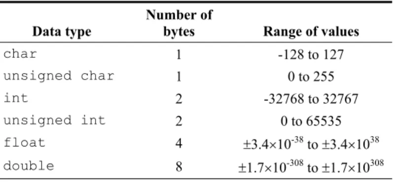
Table 1-1 A few of the fundamental data types.
Data type
Number of
bytes Range of values
char 1 -128 to 127
unsigned char 1 0 to 255
int 2 -32768 to 32767
unsigned int 2 0 to 65535
float 4 r3.4u10-38 to
r3.4u1038
double 8 r1.7u10-308 to
r1.7u10308
Data Type char
This is the data type that is primarily used to store characters. One char type data will occupy one byte in memory. The signed version is simply referred to as char and the unsigned version as unsigned char. This data type can also be used to store small integer numbers that fit into one byte of memory.
Data Type int
This is the data type that is used to store integer numbers. One int type data will occupy 2 bytes of memory in 16-bit programs. The signed version is simply referred to as int and the unsigned version as unsigned int. A synonym for int in 16-bit representation is short int.
Data Type float
This is the data type that is used to store fractional numbers. One float type data occupies 4 bytes in memory. The data type float can handle both positive and negative numbers and so there is no separate data type named unsigned float!
Identifiers
Identifiers are the symbols or variable names we will be using in our programs to identify various entities such as integers, floating point numbers, characters, memory addresses, functions, objects, classes and many more. Identifiers are case sensitiveand can be of any length.
NOTE
Identifiersmust start with a letter (upper case or lower case) or the underscore “_” character. They may contain digits (0 to 9), but not as the first character of the identifier.
Semi-colon is a must!
int a=0;
Data type Identifier
Equal sign is used to assign the initial value Assigned value
1. The data type 2. The identifier name
Figure 1-10 An example showing the syntax of a single identifier declaration.
An example of an identifier declaration is:
int a;
The data type is int and the identifier name is a. If needed, more than one identifier can be declared in one statement as shown in Figure 1-11:
Figure 1-11 An example showing the syntax of a multiple identifier declaration.
Such a declaration must be provided before being able to use an identifier in your program.
An identifier can also be declared and initialised simultaneously. In such a case, in addition to declaring the variable, we also set the identifier to take up an initial value. An example of such a situation that applies to a single identifier is:
int a=0;
The data type is int, variable name is a and it is initialised to have a value of 0 as shown in Figure 1-12.
Figure 1-12 An example - syntax of a single identifier declaration and definition.
Semi-colon is a must!
int a,b,c;
Data type
Identifiers, all of type int
Commas used to separate identifiers Semi-colon is a must!
int a;
Semi-colon is a must!
int a=0,b,c;
Data type
Identifiers, all of type int
Commas used to separate identifiers This identifier is initialised to 0
The identifier declarations we have seen so far can be combined in any manner. Such a declaration is shown in Figure 1-13:
Figure 1-13 An example showing the syntax of a general identifier declaration.
1.6 Functions with Parameters and Return
Values
In Section 1.4.1 we learned how to make a function call with a view to understand the concept of procedure abstraction. In this section we will look at a function that can be called repeatedly to carry out the addition of two numbers. We will program the function to receive the two numbers as parameters and to return their sum as the end result produced by the function. This will help us understand the role of function parameters and their return value.
Listing 1-3 Functions with parameters and return values.
/* This program calls a function (twice) to add two numbers together from within the main function and outputs the result to the screen. */
#include <iostream.h>
float Add (float a, float b) // The Add() function {
float sum;
sum = a + b; return sum; }
void main() // The main function. {
float Sum1, Sum2;
Sum1 = Add(p,q); // First call to ‘Add’ function cout << “First Sum “ << Sum1 << endl;
Sum2 = Add(r,s); // Second call to ‘Add’ function cout << “Second Sum “ << Sum2 << endl;
}
In the program shown in Listing 1-3 we have defined a new function named Add. As mentioned earlier, the definition of a function provides the return value type, the function name, the list of parameters and their types, and the body of the function. Unlike the function we have seen so far in this book, the Add() function’s pair of parentheses are not empty, meaning the function receives some parameters. In this case the Add() function receives two parameters of type float. Furthermore, the return value type of the Add() function is float. This means the function must produce a return value of type float. The value to be returned must also be specified within the body of the function in a return statement. The Add() function is reproduced below to explain its operation:
float Add (float a, float b) {
float sum;
sum = a + b; return sum; }
NOTE
According to the C language, the declaration of the Add() function is:
float Add();
Therefore, a declaration in C does not provide information about the parameters. The prototype of the Add() function is:
float Add(float, float);
Thisdoes provide information about the parameters. In C++, the declaration and the prototype of a function are exactly the same. Therefore, the prototype (and declaration) of the function Add() is:
Within the body of this function we have declared a float type identifier named sum. Then sum is assigned the result of adding a to b. Finally, the return statement sends the value of sum out of the function. Note that the type of the returned value, i.e. the type of sum (which is float), is the same as the return value type of the Add() function (specified on the first line).
The main() function of our program is shown ahead, with its function calls highlighted in bold typeface. In the first call to the Add() function, its parameters or formal arguments a and b are replaced by copies of the actual argumentsp and q, which carry real values. The parameters a and b can be viewed as placeholders. In the second call to the Add() function, its parameters are replaced by copies of r and s.
void main() {
float p=1, q=2.3, r=3, s=4.5; float Sum1, Sum2;
Sum1 = Add(p,q); // First call to ‘Add’ function cout << “First Sum “ << Sum1 << endl;
Sum2 = Add(r,s); // Second call to ‘Add’ function cout << “Second Sum “ << Sum2 << endl;
}
The value returned by the first call to the Add() function is assigned to Sum1. Therefore,Sum1 becomes the summation of p and q. In our case, Sum1 will have the value of 3.3. Similarly, Sum2 will have the value of 7.5. Since the main() function is making the calls to the Add() function, the main() function becomes the caller and at the same time the recipient of any return values. In this case, the main() function’s body is also known as the calling environment. The other lines in the main function are identifier declarations and/or definitions, and the statement used to print the values of Sum1 and Sum2 on the screen.
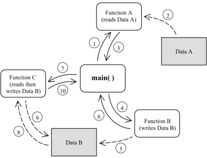
Figure 1-14 shows an example of the sequences a program goes through. This complete program consists of a main() function and a number of other functions and data. The program starts from within the main() function where various other functions are called throughout its operation.
Figure 1-14 Program with main()function, other functions and data.
1.7 Summary
Program development software is typically used to write C++ programs. This software provides an integrated environment for editing, compiling and linking programs. Built-in libraries known as Run-Time Libraries are part of the development environment and contain useful functions. To use these functions, header files are included at the start of the program to provide the respective function declarations.
A C++ program comprises the code written using correct syntax, comments, keywords, identifiers, fundamental data types, user-written data types and header files. Keywords are the reserved words that are part of the C++ language. Fundamental data types are built-in data types +and can be used to develop more complex user-written data types. Identifier names are chosen by the programmer and must not be C++ keywords. Both identifiers and functions must be declared ahead of their use in a program.
C++ programs carry out procedures by using functions that operate on specific data. This simplifies programming since the programmer only calls the function to perform a task and does not need to know how the function implements the call (this is procedure abstraction). A special type of function named main starts and ends program execution. Functions can return a value from within their body after carrying out their assigned operations. The type of this data must be specified at the time of defining the function, therefore, the function has what is known as a return
Data A
Data B
3 1
2
5 4 7
6 10
9 8
main( )
Function C (reads then writes Data B)
Function A (reads Data A)
value type. In addition to this, functions often require input data in order to carry out their dedicated operations. This input data is passed into functions with the use of their function parameters.
Early in this chapter we explained a basic C++ program comprising just the main() function. An additional function was then added to this program to carry out the same task and demonstrate procedure abstraction. Finally, a program was presented and discussed that added two numbers using a function that had parameters and a return value.
1.8 Bibliography
Kelley, A. and I. Pohl, A Book on C – programming in C, Benjamin Cummins, 1995.
House, R., Beginning with C – An Introduction to Professional Programming,
International Thompson Publishing, 1994.
Parallel Port
Basics and
Interfacing
Inside this Chapter
x
Parallel port configuration & functionality.x
Digital logic fundamentals.x
Number systems: decimal, hexadecimal and binary.A basic understanding of digital logic principles and converting data between number systems is needed before the parallel port can be used effectively. This chapter covers these topics and also describes the configuration of the parallel port itself. Concepts such as binary logic, logic levels, input/output address space and the physical connection to the port will be explained.
Working through this chapter will prime you for programming and connecting to the parallel port. You will use this knowledge in future chapters when developing programs to control and monitor hardware through the port. An understanding of basic electronic logic principles is also beneficial when constructing and testing many circuits on the interface board.
2.2 What is the Parallel Port?
Generally speaking, a port is a portion of electronic hardware that is used as an interface to connect with another electronic device for the purpose of information exchange. This connection allows information in the form of data to flow into, out of, or both into and out of the port.
The parallel port has the facility to transfer data both in and out, between the PC and the outside world. It is normally used for sending information to a printer and also known as the printer port. With older computers, the printer port is made up of circuitry residing on a separate printed circuit board (referred to as a pcb) which plugs into the PC motherboard. Newer computers, however, tend to have the parallel port circuitry integrated along with the rest of the PC motherboard.
Having a basic familiarisation with concepts such as logic families,logic levels and
noise margins helps to be able to gain an understanding how electronic devices communicate digitally. This understanding will also prove useful should electrical problems arise when using digital circuitry on the interface board.
2.2.1 Digital Logic
plastic or ceramic material with metal leads that are bonded internally with wire to the chip to allow external connection.
The two most popular types of logic circuit or logic families are TTL (transistor transistor logic) and CMOS (complementary metal oxide semiconductor). Each logic family is fabricated in a unique way, resulting in distinctive electrical operating characteristics. Some basic electrical differences between TTL and CMOS logic families are shown in Figure 2-1. There are several different versions for each family, with characteristic variations in electrical specification.
Note that some CMOS logic families can operate at voltages outside the 0V to +5V range shown. Also, the output voltage level for these circuits does depend on the level of current drawn through each output.
TTL (transistor transistor logic) CMOS (complementary metal oxide semiconductor)
a) b)
Output Level (sending)
Logic-HIGH or One Input Level (receiving) Logic-HIGH or One Output Level (sending) Logic-HIGH or One Input Level (receiving) Logic-HIGH or One
c) d)
Output Level (sending) Logic-LOW or Zero
Input Level (receiving) Logic-LOW or Zero
Output Level (sending) Logic-LOW or Zero
Input Level (receiving) Logic-LOW or Zero
Figure 2-1 Typical CMOS and TTL logic voltage levels (5V supply).
These differences in logic levels from one family to the other are very significant when connecting between them. For example, referring to Figure 2-1 quadrants a)
and b); consider the case where a TTL integrated circuit sends a HIGH logic level (+5V to +2.4V) to a CMOS integrated circuit. In this case, the TTL circuit could, at worst, send (output) a logic-HIGH having +2.4V, the lowest output voltage level when operating normally (not damaged or being over-driven). If the CMOS circuit is to correctly recognise a received (input) logic-HIGH level, this received voltage must be at least +3.2V and no more than +5V. The problem with this situation is that the TTL integrated circuit can output a signal down to +2.4V, too low a voltage level for the CMOS integrated circuit to accept as a valid logic-HIGH. The result could be that the CMOS circuit incorrectly mistakes the TTL HIGH level as a LOW level.
Figure 2-1 also shows the voltage noise margin when a data signal is sent from one logic circuit to another of the same family. Let us look at the case in which a CMOS circuit outputs a logic-LOW to another CMOS circuit, as shown in quadrant d) of the figure. The sending device will output a signal between 0V and 0.2V during normal operation and the receiving device will accept a signal level between 0V and 1.5V as a valid logic-LOW. If we use an output signal of 0.2V, the worst case for normal operation, then we can have voltage noise of up to 1.3V (1.5V – 0.2V) on this logic signal, and the receiving circuit will still recognise a valid logic-LOW. From this example we can see we have a noise margin of 1.3V. If you examine the same case shown in quadrant c) for a TTL circuit transmitting a logic-LOW to another TTL circuit, you will find that there is a noise margin of only 0.4V. CMOS circuits typically have better noise margin characteristics than TTL circuits. Other differences between TTL and CMOS circuits include their power consumption, their input current requirements, and their output current drive capacity and speed when switching states. For additional information concerning digital logic families, consult the references at the end of this chapter.
2.2.2 Parallel Port Architecture
The parallel port allows print data to be sent from the PC to the printer and data indicating printer status to be received by the PC. This data, sent by the PC, uses eight wires, to transmit a byte of information to the printer. A byte is simply a group of eight bits used together to make a unit of data. Each wire is used to transmit one bit of data at a time. Each bit of data can have one of two possible logic values, 1 or 0. Another nine wires are used to allow the PC to determine the state of the printer and control the flow of data. These nine lines are broken into a set of five input lines and four input/output lines as shown in Figure 2-2.
Figure 2-2 Parallel Port Configuration.
The three sets of wires shown in Figure 2-2 show the connection between a PC’s parallel port and an external device, in this case a printer. Each group of wires are controlled, or read, by accessing three sequential locations in the PC’s Input/Output address space, abbreviated to I/O address space. This address space is made up of a number of data storage locations used to allow intercommunication with input/output devices. It is different from the memory generally used by the computer. The PC writes data to particular I/O addresses, where the data is stored and can be accessed by external devices. Other I/O addresses are used to allow external devices to write data into storage for the PC to read, and still other I/O addresses allow bi-directional data transfer.
BASE + 2 BASE + 1 BASE
0 1st Address
Figure 2-3 I/O Addressing.
The first of the three I/O addresses is referred to as the BASE address as shown in Figure 2-3. It is the lowest address and is used as a reference from which to increment to the other two I/O addresses belonging to the parallel port. Writing to the BASE address will output eight bits of data (a byte) from the parallel port (see Figure 2-2), where each bit uses an individual wire.
Increasing order I/O Addresses
Output 8 wires Input 5 wires Input/Output 4 wires
PC (Parallel Port) Printer
The next address in this block has a numerical value one more than the BASE address, so we label it the BASE+1 address. The BASE+1 address has access to the five input data bits to the PC. This address can only be used to read the state of these five signals.
The third address of this set is labelled the BASE+2 address, being two addresses past the BASE address. This address location is used to control the four bi-directional data bits of the port. Using this address, we can read and write to these four bits.
NOTE
Beware: the four BASE+2 lines used for input and output are NOT ‘strict’ logic outputs. The parallel port interface often has resistors and capacitors connected to these lines to reduce the influence of electrical noise. This causes their states to change much slower than a strict logic output, meaning that erroneous recognition of data can occur when connecting with certain types of logic families.
In addition, due to variation in the individual capacitor values, these signals do not switch at ‘exactly’ the same time (synchronously). This non-synchronous (asynchronous) switching of BASE+2 outputs can cause data transfer problems with data interfaces designed to work synchronously.
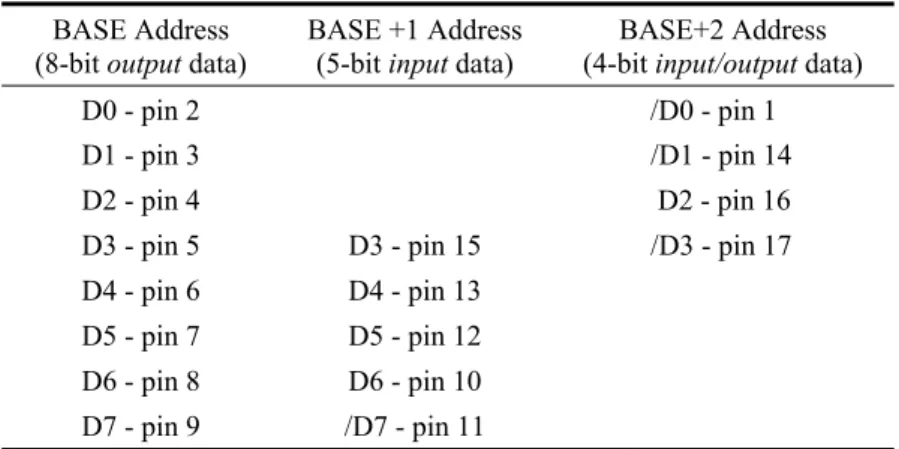
Table 2-1 provides a summary of the data bits and D25 connector pins that the parallel port connector uses for each of the three port addresses. Each wire in the cable linking the port to the external device (usually a printer), carries the signal of a particular data bit for that port address. The BASE and BASE+2 addresses have their data bits commencing from D0 upwards. The BASE+1 address, however, starts at data bit D3.
Some data bits used by BASE+1 and BASE+2 addresses are inverted by the parallel port circuitry. These inverted bits are marked by a “ / ” character preceding the letter “D” of that bit. This signal convention is also used on the interface board
schematic diagrams which show detailed electrical interconnections. When using these data bits, the program must compensate for this inversion in order that signals are output from the port or read in through the port as intended.
Table 2-1 Parallel Port D25 Connector Pin Assignment. BASE Address
(8-bitoutput data)
BASE +1 Address
(5-bitinput data)
BASE+2 Address
(4-bitinput/output data)
D0 - pin 2 /D0 - pin 1
D1 - pin 3 /D1 - pin 14
D2 - pin 4 D2 - pin 16
D3 - pin 5 D3 - pin 15 /D3 - pin 17
D4 - pin 6 D4 - pin 13
D5 - pin 7 D5 - pin 12
D6 - pin 8 D6 - pin 10
D7 - pin 9 /D7 - pin 11
Note: “/ ” denotes the signal bit is inverted internally by the parallel port circuitry.
D25 pin numbers 18 to 25 are not shown in Table 2-1. They are all connected to the PC electrical ‘ground’ which is connected to the interface board through the interface cable (Figure 2-4). This cable has a D25 male connector at both ends, connected by individual wires in a “one-to-one” arrangement (D25 pin 1 of one connector to the D25 pin 1 of the other connector; likewise for all remaining pins).
Figure 2-4 D25M to D25M Cable.
NOTE
Data bits D0 to D2 of BASE+1 address are not connected to the parallel port circuitry inside the PC. The same holds true for D4 to D7 of the BASE+2 address. Reading these particular bits will produce invalid data.
2 metres
2.3 Data Representation
As mentioned previously, computers use ‘ON’ and ‘OFF’ states (high and low voltages) to store data, termed binary data since we have only two states. This leads to the representation of numbers using the binary (on/off) number system. The binary system is based on raising the number two to increasing integer powers to form higher and higher digit values. We can see how such a system works by comparing it with our familiar decimal number system. Decimal numbers are based on raising the number ten to higher and higher integer powers.
For example, the decimal number 25 is broken down as follows:
25 = 2x101 + 5x100
= 2x10 + 5x1
Decimal 25 is equivalent to the binary number of 11001 as follows:
11001 = 1x24 + 1x23 + 0x22 + 0x21 + 1x20
= 1x16 + 1x8 + 0x4 + 0x2 + 1x1 = 25 (decimal)
NOTE
The binary digit to the far right has the lowest weighting and is known as the least significant bit (LSB). Conversely, the left-most binary digit has the highest weighting and is termed the most significant bit (MSB).
Binary numbers with many digits are not easy to read. To solve this problem we use a more convenient number representation named hexadecimal. This system is based on sixteen number states.
The decimal number system uses ten unique Arabic numerals being 0, 1, 2, …, to 9. In hexadecimal representation we need sixteen unique numerals. The first ten hexadecimal digits use Arabic numerals 0, 1, 2, ..., to 9, however, we must use unique digit representation for the remaining numbers ten to fifteen. This is done by using capital letters A, B, C, D, E and F to represent ten, eleven, twelve, …, to fifteen.
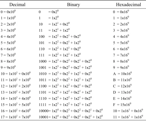
Table 2-2 Number System Conversions.
Decimal Binary Hexadecimal
0 = 0x100 0 = 0x20 0 = 0x160
1 = 1x100 1 = 1x20 1 = 1x160
2 = 2x100 10 = 1x21 + 0x20 2 = 2x160
3 = 3x100 11 = 1x21 + 1x20 3 = 3x160
4 = 4x100 100 = 1x22 + 0x21 + 0x20 4 = 4x160
5 = 5x100 101 = 1x22 + 0x21 + 1x20 5 = 5x160
6 = 6x100 110 = 1x22 + 1x21 + 0x20 6 = 6x160
7 = 7x100 111 = 1x22 + 1x21 + 1x20 7 = 7x160
8 = 8x100 1000 = 1x23 + 0x22 + 0x21 + 0x20 8 = 8x160
9 = 9x100 1001 = 1x23 + 0x22 + 0x21 + 1x20 9 = 9x160
10 = 1x101 + 0x100 1010 = 1x23 + 0x22 + 1x21 + 0x20 A = 10x160
11 = 1x101 + 1x100 1011 = 1x23 + 0x22 + 1x21 + 1x20 B = 11x160
12 = 1x101 + 2x100 1100 = 1x23 + 1x22 + 0x21 + 0x20 C = 12x160
13 = 1x101 + 3x100 1101 = 1x23 + 1x22 + 0x21 + 1x20 D = 13x160
14 = 1x101 + 4x100 1110 = 1x23 + 1x22 + 1x21 + 0x20 E = 14x160
15 = 1x101 + 5x100 1111 = 1x23 + 1x22 + 1x21 + 1x20 F = 15x160
16 = 1x101 + 6x100 10000 = 1x24 + 0x23 + 0x22 + 0x21 + 0x20 10 = 1x161 + 0x160
17 = 1x101 + 7x100 10001 = 1x24 + 0x23 + 0x22 + 0x21 + 1x20 11 = 1x161 + 1x160
When developing programs, it is sometimes necessary to output digital signals through a port as one or more bytes of data. The signals to be output form binary bit patterns, which are more conveniently represented within program code as hexadecimal numbers. At other times you will need to represent incoming binary data sent from external devices as hexadecimal numbers. The following examples demonstrate the conversion of a binary number into hexadecimal.
We can obtain the hexadecimal representation for a binary number if we divide the binary number into groups of four digits starting from the least significant digit or bit (LSB, right-most digit of the number). Note that when we break a byte into two groups of four bits, we have what is termed two nibbles of data.
10001 =
=
1 0001
1 1 hex
(hexadecimal numbers are often written using a 0x prefix , i.e. 0x11)
1010001101 = =
10 1000 1101
2 8 D hex (0x28D)