Complex Systems Informatics and Modeling Quarterly CSIMQ, Issue 9, December 2016/January 2017, Pages 1–27 Published online by RTU Press, https://csimq-journals.rtu.lv https://doi.org/10.7250/csimq.2016-9.01
ISSN: 2255-9922 online
An Improved Model Facet Method to Support EA Alignment
Jonathan Pepin1,2?, Pascal Andr´e1?, Christian Attiogb´e1? and Erwan Breton2?
1AeLoS Team - LINA CNRS UMR 6241 - 2 rue de la Houssini`ere BP 92208 44322 Nantes, France 2Mia-Software - 4 Rue du Chˆateau de l’Eraudi`ere, 44300 Nantes, France
[email protected], [email protected], [email protected], [email protected]
Abstract. Information System evolution requires a well-structured Enterprise Architecture and its rigorous management. The alignment of the elements in the architecture according to various abstraction layers may contribute to the management but appropriate tools are needed. We propose improvements to theFacettechnique and we develop accompanying tools to master the difficulties of the alignment of the models used to structure an Enterprise Architecture. This technique has been experimented on many real life cases to demonstrate the effectiveness of our EA alignment method. The tools are already integrated in theEclipse EMF Facetproject.
Keywords: Enterprise Architecture, legacy information systems, alignment, evolution, model mapping, tools.
1
Introduction
Enterprise Architecture engaged much interest by academia and practitioners during the last decade. Numerous methods have been proposed [1], [2], such as TOGAF or Zachman framework, to design and develop an enterprise’s organisational structure, its business processes, its information systems, and its infrastructure. As mentioned by Lankhorst [2], Enterprise Architecture (EA) captures the essentials of the business, IT and its evolution. The idea is that the essentials are much more stable than the specific solutions that are found for the problems currently at hand. Architecture is therefore helpful in guarding the essentials of the business, while still allowing for maximal flexibility and adaptivity. Modelling languages such as ArchiMate have been proposed [3] to enable the specification of architectures from business goal to technology infrastructure. However, effective technologies and tool support are still missing [4], [5], [6], [7], [8], [9], especially when considering legacy systems with a bottom-up approach [10]. EA cannot start from scratch, a method is needed to integrate existing information and build the current state (as-is) of a business [7].
?Corresponding author
c
2016 Pepin et al. This is an open access article licensed under the Creative Commons Attribution License (http://creativecommons.org/licenses/by/4.0).
The IT evolution is driven by technological changes (new hardware and software technologies) and by continuous business changes imposed by market competition or law obligations. These maintenance activities are very expensive, especially if they do not boost the business. But, while numerous contributions emerged to answer the Business-IT alignment problem [5], [7], [8], assisting the maintenance of legacy systems is still challenging [9]. For instance, mastering the evolution of information systems (IS) according to an EA approach requires:
• To reduce the distance between the business and its information technology (IT). The Business/IT Alignment (BITA) contributes to solve that problem by providing means to link the different layers.
• To master the transition between various IS versions in order to compare different evolution scenarios before deciding the one to develop.
Consequently, our motivation is to help decision makers to build the alignment of legacy systems with related business models in order to underline the cross effects of IT and business evolutions. However, we focus more on operational concerns than on a theoretical vision.
Quoting Zachman, Anaya and Ortiz [11] define “an Enterprise Architecture as a set of descriptive representations (i.e. models) that are relevant for describing an Enterprise”. Consequently, we focus on the Model Driven Engineering (MDE) field to find operational solutions. From the MDE point of view, the alignment problem is interpreted as mapping models, provided that we have business and IT models for various layers in the EA representation. Among the model composition techniques we retain the model mapping ones because they keep the integrity of the composed models.
Our primary objective is to establish and maintain a tight link between the applications of the legacy system and the business models of the enterprise. This link makes them aligned and the mismatches can be revealed (as-is) and avoided in the future state of the system (to-be). Our research methodology is inspired of three approaches (process, build and experimental): we analyse the current EA practice and propose an operational method, we build a proof of concept and experiment it to show its applicability.
The first contribution of this article is a non-intrusive technique to map models based on the Facets, this technique is implemented and contributes to the Eclipse EMF Facet project. The second contribution is the application of this technique to EA maintenance issues as described in [12]. We propose a method (including EA models, a top-down and bottom-up process and automation tools) to process Business-IT Alignment in the EA maintenance for legacy systems. The improved facet technique is located in the core of the alignment tool support. We led experiments on real life case studies to demonstrate the effectiveness of this method.
The article is structured as follows. Section 2 summarises the background and goals: using models for EA maintenance. In this context, model mapping helps to represent alignment links. In Section 3 we compare different ways to map models according to four criteria and we argue the choice of the Facet technique. Section 4 presents our enhanced Facet method that covers all the criteria. The instrumented result is provided to the community and we apply the technique to the EA context. We detail the method and its supporting tools in Section 5. We report on the experiments in Section 6. In Section 7 we discuss related works. Finally, Section 8 concludes the article and draws some perspectives regarding the proposed method.
2
Model Mapping Techniques for Enterprise Architecture
This section sets the context and the background of our study.
2.1 Information Systems Models and Views
the 2000s the Model Driven Approach (MDA) boosted the idea that models are the foundation for building enterprise-scale software solutions [13]. Vara and Marcos showed the interest of developing information systems using the MDE in [14]: the techniques become mature, interoperable and customisable.
Information Systems are very complex and an unique IS model is definitely not sufficient. Developing or analysing IS requires multiple kinds of models following multiple objectives. Since these terms are overloaded in the literature, we select some usual model classification criteria and discuss relations between models in each category:
Abstraction (andrefinement). Abstraction hides the implementation details. During the development of system, high level abstraction models refer to system analysis and design while low level ones refer to implementation and deployment of the solutions. The Object Management Group (OMG) identifies three types of models in MDA:Computation Independent Model(CIM),Platform Independent Model (PIM),Platform Specific Model(PSM). A previous version of the included anImplementation Specific
Model(ISM) [13].
People often useabstraction layersto represent the organisation of complex models. Typical examples are the ISO stack of protocols and services for telecommunications or the service oriented architecture approach (SOA).
The kinds of relations between models of different layers are refinement or traceability. Sometimes inheritance is used to materialize the abstraction between comparable concepts (calledmodel elements).
Dimension. Analogously to mathematics, a dimension represents a part of a system knowledge such that all the parts describe the whole system. The object modelling technique OMT (a precursor of UML) popularised the practice of representing a system according to three-dimensional (3D) models: structural, functional and dynamic. The Model-View-Controller popularised another 3D organisation. The UML 2 specification, as well as its structured programming methods, consider only two dimensions (2D): structural vs. behavioural.
A coordination model, as a glue, establishes the causal relations between models of the different dimensions.
Composition. A model is composed of elements and other models.Model compositionis both the operation that builds a new model from input models but also the relations between the composed models. Several semantics exist for it as discussed in Section 7. A tight semantics, calledcomposition (orwhole-part orstructural dependency), means that the component belongs to the composite. This is a transitive and asymmetric relation which is also the basis for the Component-Based approach. A loose semantics is called mapping (or association or aggregation), meaning that the related models (or elements) stay independent.
The kinds of relations between models of the same layers aremappingandcomposition.
Evolution. Organisations, software and a fortiori models evolve. Models evolutions mainly follow the system life cycle but they can be driven by refactoring or reverse engineering activities. MDA transformations support model-driven evolution [15], [16].
The kinds of relations between models of different generations are traceability, change or version management, but one can find more specific links related to refactoring operations.
View, point of view, and transformation. The term view is generic and often overloaded, depending on the authors or the contexts. A view is an independent representation of a system from the perspective of a related set of concerns [17]. The dimensions, as defined above, are orthogonal views that describe together the whole system. In TOGAF, a view is what you see, a viewpoint is where you are looking from and a view consists of models.
Model transformationprocess computations on models and views [13]. It helps in automating the model calculus in order to getconsistent viewsorcrossed viewsof a system.
2.2 Enterprise Architecture Layers
Enterprise Architectures comprise numerous artifacts related to business or IT views of
Information Systems (IS) [2], [9]. These artifacts are structured in models (or ontologies) which are organised in layered hierarchies in EA frameworks.
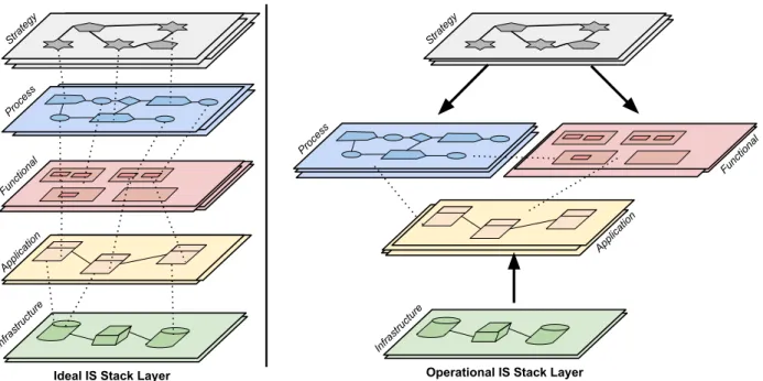
Common EA representations mix viewpoints and abstraction in a single stack of models where the business viewpoint drives the high-level layers and the IT viewpoint is concerned with the low-level layers. As an example, Figure 1 sketches two five-layers stack of models. Each layer represents a (set of) model according to the above called abstraction criteria. A set of models is coordinated according to thedimensioncriteria. The links between elements of the layers support thealignment of models. From the IT perspective, the field of EA has been focused on achieving BITA or ensuring that IT aligns with the business strategy [6].
The left part of Figure 1 is qualified as “ideal alignment” because it is never obtained from stem to stern in practice. The right part of Figure 1 reflects a more operational approach given in [12] where alignment is reduced to a core triple of models. The core models are populated by the other layers. This approach will be described in Section 3.2.
Strategy
Process
Functional
Application
Infrastructure
Ideal IS Stack Layer Operational IS Stack Layer
Strategy
Application
Functional Process
Infrastructure
Figure 1.Information system layers and ideal alignment
Model Driven Enterprise Architecture. The model-based vision of EA makes Model Driven Engineering (MDE) a natural candidate for a technical support for EA activities as well as for information system development [14]. Brown [13] illustrated the use of MDA to connect business and IT at IBM. Ostadzadeh et al. [18] propose an MDA-based generic framework for supporting the modelling and synchronization of hierarchical systems. Using MDE improves productivity, portability, interoperability and documentation.
Enterprise Architecture maintenance. The goal of EA maintenance, as part of IS maintenance, is to establish and maintain the consistency of the stack of models before and after the maintenance operations of the applications of the legacy enterprise system. As mentioned above, linking the application and business models makes them aligned, reveals the mismatches (as-is), and avoids conflicts when the system changes (to-be). This goal underlines two activities, alignment and
evolution. The BITA and Evolution topics are parts of large, active and open research fields. Both belong to the EA maintenance challenges [9]. BITA has a multidimensional nature (people, culture, organisation, relations, quality, etc.) [22], [23] while EA evolution includes the big chapter of software evolution [24]. We consider here the subset of these domains covered by IT e.g. people are not IT concepts. These concepts are handled by MDE techniques where the artefacts are represented in linkable models. We also take care of tool support for the de factoMDE standards such as OML, OCL, MOF, EMF. In this context, EA Alignment and Evolution can be implemented bymapping models. This is a practical answer to the initial challenge.
In the remaining of this article we will focus on BITA while EA evolution will be the subject of a discussion in Section 7.
3
Comparing Model Mapping Techniques for Enterprise Architecture
Within MDE, model composition is an active research field that helps in automating the process of recombining models with another one to get dedicated and consistent views of the system. Most composition techniques are built for a specific purpose in a given context [25]. Considering alignment and evolution, we reduce that field to model mapping and we retain five mapping techniques: merging, extension, annotation, weaving, and facets. For the sake of simplicity, mapping will be here a binary operator. We compare the five mapping techniques according to four criteria and we will choose the most appropriate one for our concerns:
1. Non-intrusiveness: the mapping must not modify the individual models, because they evolve independently.
2. Semantics: the mapping is not simply a set of links, it supports a semantic relation to connect differently the concepts with an equivalence class of interpretation (an ontology of the concepts and links).
3. Link Resolution: the mapping techniques must provide a mechanism to navigate by mapping links directly from the source model to the target model and reciprocally.
4. Serialization: the mapping links must be persistent to store the information about work environment.
These criteria are enumerated in order of importance. Non-intrusiveness is a critical criterion. Before comparing the approaches, we present the EA Framework we used to experiment the techniques and to illustrate the comparison.
3.1 The EA Framework
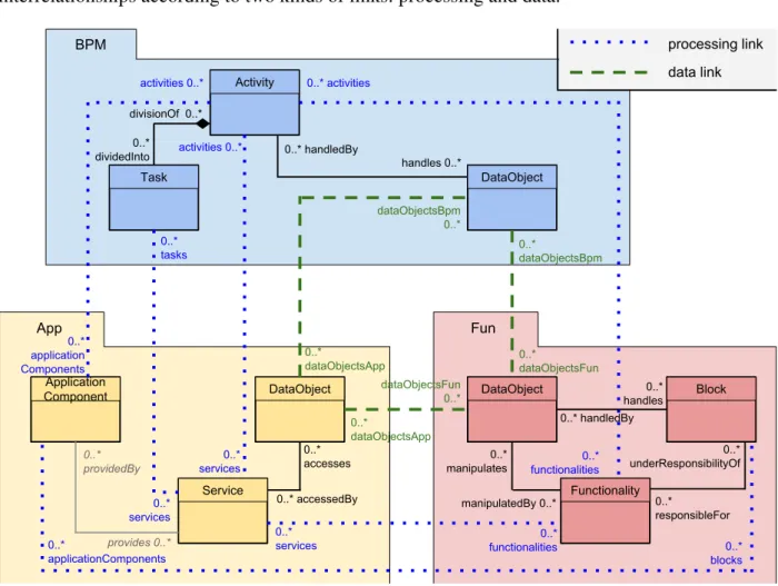
In a previous work [12], we defined a generic EA framework to capture the findings of legacy systems and provide a as-issnapshot of a system to be compared later with possibleto-bestates. Our EA framework is made of a triple of core generic meta-models. Figure 2 illustrates the part of the meta-models definition and interrelationships that are needed for the explanations.
• The business meta-modelBPMis compatible with standard notations such as BPMN or UML activity diagram. AProcessdescribes a sequence of Activitiesmade of Tasks that operate on DataObjects. A Process can be triggered by an Actoror another process through aTransition.
The business model is an embodiment of the business strategy (top-down) provided by the legacy documentation, or written manually.
• The functional meta-modelFunsplits the Information System in functionalBlocks. Each block can handleDataObjectand manipulateFunctionality. Blocks can be composed of sub-blocks.
Usually this model is provided (or not) by enterprise architects.
The meta-model interrelationships support our BITA definition. Figure 2 shows interrelationships according to two kinds of links: processing and data.
Activity DataObject Task Application Component DataObject Service DataObject Functionality BPM App Fun
divisionOf 0..*
0..*
dividedInto 0..* handledBy
handles 0..* 0..* accesses 0..* accessedBy 0..* manipulates manipulatedBy 0..* 0..* application Components 0..* services 0..* tasks activities 0..* 0..* services 0..* functionalities activities 0..* 0..* activities
0..* functionalities processing link data link dataObjectsBpm 0..* dataObjectsFun 0..* 0..* dataObjectsApp 0..* dataObjectsApp 0..* dataObjectsBpm 0..* dataObjectsFun 0..* services 0..* providedBy provides 0..* Block 0..* handles 0..* handledBy 0..* responsibleFor 0..* underResponsibilityOf 0..* applicationComponents 0..* blocks
Figure 2.EA meta-model interrelationships
• AProcessing Linkmaps a concept of one layer to a similar concept of a different layer. As an example, theServiceof theApplayer is linked to theActivityof theBPMlayer and also to the Functionalityof theFunlayer. For an application model with few details and without services, one can just linkApplicationComponentApptoActivityBPM.
• A Data Linkmaps all DataObject concepts between our generic EA meta-models; then we have three ways to link the three meta-models.
3.2 Mapping Techniques
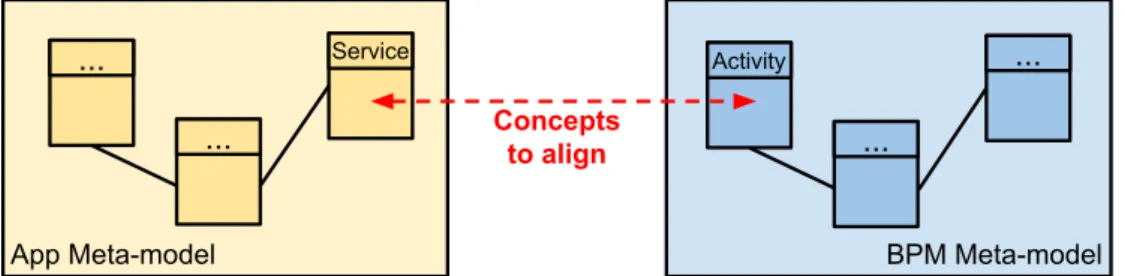
To illustrate the different mapping techniques, we use the simple example of Figure 3 extracted from Figure 2. We experimented all the techniques in the context of the above EA framework.
between these two model elements. We use the following UML-like conventions: a line represents an association link, a line ended by a diamond is a composition association, a line ended by a black arrow is a unidirectional association and a line ended by a white arrow denotes inheritance.
...
... ...
...
Concepts to align
App Meta-model BPM Meta-model
Activity Service
Figure 3.Alignment of two concepts between App and BPM meta-models
Merging of meta-models. Merging creates a global meta-model including all the concepts of the input meta-models. In Figure 4, theServiceandActivityconcepts are merged in the newAppBPM meta-model with a new (mapping) association namedimplements.
... ...
AppBPM Meta-model
Service ...
... Activity
Figure 4.Merging App and BPM in a unique meta-model
The main drawback is that a unique meta-model is less flexible to evolution and may lead to some confusion. The merging also consists of modifying only the initial meta-model by adding explicitly new attributes.
+ The global meta-model requires no additional processing to be used.
- Requires a new global meta-model for each case study, this prevents Domain Specific Languages, DSLs. - Maintaining meta-models is complex since their life cycles are coupled.
- At the model level, merging requires specific tools likeEclipse EMF Compare.
- Working with big size models increase the risk of finding model elements conflicts, including those that do not belong to alignment. Resolving the conflict can take much time.
Extension of meta-models. Each meta-model is extended in order to include the concepts from the other related meta-model by adding a (mapping) associations. As depicted in Figure 5, the conceptActivityfrom the meta-model BPM is referenced by a new link with the conceptService into the meta-model App; and the concept Servicefrom the meta-model App is referenced by a new symmetric link with the conceptActivityof BPM.
This approach violates the construction of the Domain Specific Language (DSL) supported by a meta-model. Another drawback is to anchor the concepts to be aligned while EA needs flexibility. Consequently, any evolution of the EA meta-models will involve the creation of an extended meta-model for each new version.
+ The extended meta-models require no additional processing to be used. - Requires a new extension for each case study, this prevents DSL.
...
... ...
...
Activity Service
@Activity @Service
App Meta-model BPM Meta-model
Figure 5.Extension of App and BPM meta-models
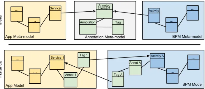
Annotation of models. Annotation facilities enable one to add independent cross-cutting concerns to the models by using tags. As depicted in Figure 6, the conceptServicefrom the App meta-model and the concept Activity from the BPM meta-model extend theMAnnotedElement concept from the Annotation meta-model. At instance level, the annotation Annot 1is created and linked with the service Service 1 of the App model. On this annotation a tagTag 1is created and references the activityActivity Aof the BPM model. Similarly the annotation Annot Ais created and linked with the activityActivity Aof the BPM model and the tagTag Areferences the serviceService 1in the App model.
...
... ...
...
App Meta-model BPM Meta-model
Activity Service
Annotation Meta-model
Tag
...
... ...
...
App Model BPM Model
ActivityA Service 1
Instance
Meta
Annoted
Tag 1
Annot 1
Annot A Annotation
Element
Tag A
Figure 6.Annotations between App and BPM meta-models
We experimented the annotation technique with the small meta-model called MAnnotation inspired by the Ecore Eannotationand developed by Mia-Software1. It is illustrated by Figure 7. TheMAnnotedElementinterface can be extended by any class from another meta-model and each MAnnotationis marked by severalMTags.
Creating annotations is very simple and a link resolution is supported natively by the EMF standard implementation. Therefore, it is possible to navigate through different models by the MAnnotation. However, we faced the following problem: the links have no conformance rules, each concept can be linked with another one without avoiding meaningless annotations.
+ Inter-model navigation is enabled by the native EMF resolution.
- Each concept subject to alignment must be modified, this technique is intrusive.
- If a standard notation e.g. BPMN or UML is used, the extended meta-model will not conform to the notation specification.
- The annotation links are not typed, the semantics of the alignment model is not necessary preserved.
Figure 7.Meta-model MAnnotation
Weaving of models. Model weaving is a flexible and non-intrusive mapping technique that has been already experimented in the MDE field:“Model weaving operations are performed between two or more meta-models, or between models. They aim to specify the links, and their associated semantics, between elements of source and target models” [26]. Model weaving involves the creation of an independent model which refers to the models to weave and the links between their concepts. Weaving is achieved at the model level. As depicted in Figure 8, the linkLink 1connects theService 1instance of the App meta-model with the activityActivity Afrom BPM meta-model.
...
... ...
...
App Meta-model BPM Meta-model
Activity Service
Weaving Meta-model
Link
Object
... ...
...
... ...
...
App Model BPM Model
ActivityA Service1
Weaving Model
Instance
Meta
Object 2 Object 1
Link1
Figure 8.Weaving between App and BPM meta-models
Many weaving tools are developed with Eclipse platform Plug-ins based on the EMF technologies e.g. Atlas Model Weaver (AMW) [26] and Virtual EMF [27]. AMW includes a transformation mechanism with ATL2 to create an automatic weaving. Virtual EMF provides a
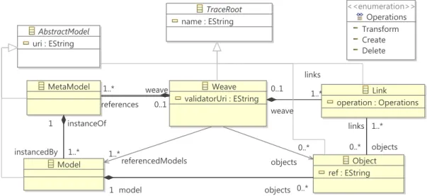
visual assistant to edit two models from different meta-models and to create links between concepts with a drag and drop. Unfortunately, editors are no longer supported and compatible with recent Eclipse versions (we experimented with Eclipse Juno 4.2). But we got inspired by them to create our own weaving meta-model depicted in Figure 9.
However, this solution is still limited: the created links have yet no conceptual meaning, they are generic and can store any kind of concepts; the navigation by resolving link is expensive because it requires a complete traversal of the models mapping graph.
+ The original models are not modified.
- The link between two models can be resolved only if the editor is compatible with the mapping meta-model.
- The navigation from a concept of one model to a concept of another model requires to visit the full weaving model.
- The annotation links are not typed, the semantics of the alignment model is not necessary preserved.
Figure 9.Our weaving meta-model
EMF Facet. Facet is a kind of weaving technique that extends a meta-model definition without intrusion. It is implemented in the Eclipse open-source project EMF Facet. A Facet provides natively a mechanism to add virtual attributes or operations as new features to existing concepts; a new Facet feature systematically calls a query, written in Java, OCL or Javascript, that returns a value.
As depicted in Figure 10, we create, at meta-model level, a new FacetSet supporting the new definition between meta-models to extend (App and BPM). The FacetSet enables to add virtual properties: two new cross-referencesimplementsandimplementedBybetween theServiceconcept from the App meta-model and theActivityconcept from the BPM meta-model. At the model level, we can create links between services and activities from App and BPM instances as if properties were native to their original meta-models.
...
... ...
...
App Meta-model BPM Meta-model
Activity Service
Facet Model (FacetSet)
implementedBy
...
... ...
...
App Model BPM Model
Activity A Service 1
Facet Serialization
Instance
Meta implements
Facet Meta-model
ReferenceFacet
Object Reference 1
Object Reference A
The technique is interesting but some drawbacks remain.
+ The original models are not modified.
+ The navigation from a concept of one model to a concept of another model need not to visit the full weaving model.
+ The links are typed, the semantics of the alignment model can be checked.
- The queries must be executed during the model loading, if the model is voluminous, the computation times will impact the response time.
- The value of new features is computed by queries only and cannot be assigned, as classical attributes or references in an ordinary meta-model.
- There are no persistence/serialisation mechanisms.
Comparison results. We summarise the comparison results in Table 1. Considering the evolution issue, our findings are: the extension and merging techniques do not provide another solution than modifying the original meta-model by adding explicitly new attributes ; the weaving technique can link a new Class with the new attributes from the evolution, but complicates the expressibility.
Table 1.Comparison between mapping techniques
Technique Non intrusive Semantics Link Resolver Serialization
Merge 7 3 3 3
Extension 7 3 3 3
Annotations 7 7 3 3
Weaving 3 7 7 3
Facets 3 3 3 7
The merging and extension techniques are candidates with three of four criteria, but non-intrusive criterion is essential when considering evolution. To obtain mapped models, we don’t want to handle different versions of the meta-models through transformation steps: holding object model integrity between two different versions is critical (identifier conflicts). Facet is the most promising approach except to the main drawback mentioned above. Currently, adding new features or achieving alignment or evolution is only possible by queries. But we also need to perform manual weaving and to serialize the mapping links in intermediate models. Section 4 will address this shortcoming.
4
An Enhanced Facet Technique and Support
The enhanced Facet technique improves EMF Facet by avoiding the above mentioned shortcomings and making it fulfill the “serialization” criteria. Before presenting the improvements in Section 4.2 we first explain the essential of EMF Facet in Section 4.1.
4.1 The EMF Facet
Eclipse EMF Facet, a runtime meta-model extension framework3 is composed of four parts: Facet, Customization, Widgets and Query. Facet and Customization are the two useful parts for IS alignment: one canextend modelsby adding attributes to existing models and weave models by linking the various concepts between the layers.
Facet. A Facet provides a new view on a model which is helpful to categorize model elements with new classification, to add information on model element, to easily navigate between model elements with new derived links. A Facet provides a virtual mechanism to add attributes, references or operations on a model without modifying the initial meta-model. Several Facets can co-exist and be loaded/unloaded on demand without re-opening the model instance.
As illustrated by Figure 11, the Facet meta-model extends the metaclass (EClass) from the EMF Ecore meta-model. Each facet has at least a name and a meta-class type. A Facet optionally extends an existing Facet and refers to the base meta-class by its absolute Universal Resource Identifier (URI). A Facet has three kinds of features:FacetAttribute,FacetReferenceandFacetOperation. A FacetAttributehas a name, a multiplicity and the meta-class type as inFacetReference.
Figure 11.EMF Facet meta-model
The Facet applicability is checked by optional conformance rules. A Facet may contain FacetAttribute, FacetReference, and FacetOperation which values are returned by query evaluation. Facets are contained in aFacetSetthat can be contained by anotherFacetSet.
Customization. EMF Facet provides a customization mechanism to define a new appearance of model elements; it enables to change label, icon, color (background and text), and font characteristics. ACustomizationis aFacetSet.
4.2 Improving the Persistency of References and Attributes
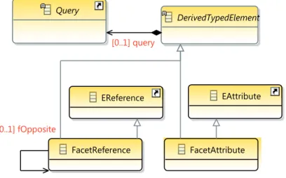
query on DerivedTypedElement is replaced from 1..1 to 0..1. This feature enables to get the values of FacetReference and FacetAttribute without using a query. Furthermore, we added a new EReference named fOppositeto create a reflexive reference mechanism like eOppositeon EReferencein the Ecore meta-model. After the modification of the meta-model, we implemented the new behaviour in the Java source code of the Facet engine calledFacetManager. To store the new virtual attributes and references without queries, we extended the existing mechanism of Facet persistence, theSerializationManagerengine.
FacetAttribute FacetReference
DerivedTypedElement
EReference EAttribute
Query
[0..1] fOpposite
[0..1] query
Figure 12.EMF Facet meta-model modifications
The extended EMF Facet can now extend and weave EA models. We updated Table 1 according to the Serialization criteria, making the new Facet be the most efficient technique. We successfully submitted it as a contribution to the open-source Eclipse EMF Facet4.
5
Implementing the Facet in an EA Context
We describe the way we apply extended Facet to address the EA models alignment and evolution. First, we extend the meta-classes by creating new FacetSet containing all facets; then we map the models by the facets by the way of tooling facilities; last we apply alignment or evolution procedures.
5.1 Extending Existing EA Model by Facet Definition
The common feature of EMF facet (see Section 4.1) enables to extend and reference all existing EA meta-models with new possibilities. We illustrate it with two examples.
• Enhancement: Suppose anApplicationmeta-model describing the IT component architecture and aBusiness Processmeta-model describing task and activities supplied by the information system. In Figure 13, the new attribute artifactUri of type string is defined in the Activity meta-class of theBusiness Processmodel, it stores the artefact URI.
• Alignment: Suppose also that we want to produce an alignment between models concepts to navigate between each EA layer. Thus, we create on the same Activity(cf. Figure 13) a new reference to add a bidirectional link between theActivity fromBusiness Process meta-model and theApplicationComponent meta-class from theApplicationmeta-model.
Figure 13.FacetSet definition example
5.2 Refactoring EA Model by Customisation
As we can see in Section 4.1, the custom feature of EMF Facet enables to realize dynamic evolutions of EA models. We suggest two scenarios.
• Concept naming: In practice, each enterprise has a specific and different vocabulary for the same concepts. In order to enable mapping between concepts, the enterprise may choose a good candidate meta-model with a different lexicon, but to avoid misunderstanding, it is preferable to rename the involved concepts.
• Classification: With the growth of number of instance concepts in model, it is necessary to classify elements in new category. In modelling terms, we want to create sub-classes by inheritance. EMF Facet allows to create new classes with specific names and icons, and the new class instances are computed from existing instances by a query.
These scenarios could be implemented with static model transformations, but again the main advantage of EMF Facet is that it avoids the problem of model integrity between two different versions. Dynamic refactoring does not destroy the original model and it is possible to create different viewpoints that are applicable on demand.
Example. Suppose an Application model containing several IT component architecture name “ApplicationComponent”. All ApplicationComponents have the same name and icon, but they have an attribute “type” with two different values: Application or Component. In Figure 14, using an OCL query, we compute the new label name with the two attributes from the ApplicationComponent concept : type + ‘ ’ + name. Another Java query returns the new icon to applications. The result is presented by the Figure 15.
Figure 15.Classification result
5.3 Facet Tooling
In order to exploit Facet extensions at the model instance level, we developed several tools and wizards to set the value of the attributes and references. Performing the EA procedures is implemented by query navigation and evaluation.
Property value. Since we have noProperty View to set the value of reference and attribute, we reuse the open sourceEclipse Modisco TreeEditor compatible with EMF Facet to open the model in a tree viewer and to enable our new FacetSet to display the new features. However, there is no possibility to set the value of features, TreeEditor is a read-only viewer. In Eclipse it is common to use the Property View for editing value. Consequently, we added the EMF Property View on TreeEditor to edit an EMF model, but it displays only native features from the meta-model and not the virtual ones of our FacetSet. For this purpose we develop a newProperty View(Figure 16) to display and edit native and virtual features. This improvement was also proposed and included into the EMF Facet project.
EA model weaver. The ergonomics of theProperty Viewis too limited to provide user assistance to map model element one to another. We therefore developed a specific weaving editor with multiple views as illustrated by Figure 17. On the right part of the figure, an outline displays the different models to weave. On its left part, a specific view organizes the weaving result by facets. This design allows to drag and drop elements from right to left to link elements by references corresponding to theFacetSetdefinition.
Figure 16.Property view to edit Facet and original features
Figure 17.EA model weaver editor
model layers by the FacetReference, but it is not very convenient. Architects also require facilities related to quality, e.g. to define various kinds of alignment or traceability metrics to drive a dashboard. OCL is the standard language to express statements including model navigation. Since EMF offers OCL expression parsers on Ecore models, we extended the query engine in order to make Facet virtual feature compatible and used as property in OCL statements. This extension was made publically available in a plug-in to EMF Facet project.
We overviewed how to implement quickly and simply Facets on existing meta-models. The tool assistants were useful to lead our experiments.
6
Experimenting Business-IT Alignment With Case Studies
The extended Facet technique implementation acts as a proof of concept for our experiments in the context of information system maintenance of three french mutual insurance companies renamed here by SAMM, SAMI, and SAMUT for confidential reasons. We worked with consultants that represented the end-users.
overview the implementation, then we describe the case studies, and we finish with the lessons of the experiments with the Facet technique.
EMF Facet
Alignment meta-model
links (FacetSet)
Inputs
Output
Definition
Application model
Weaving model (EFS)
Engine
Functional model
IHM
Weaving editor
BPM model
Figure 18.Facet application
6.1 Implementation
Briefly, the three meta-models of the EA framework of Section 3.2 are implemented with Eclipse EMF by their corresponding Ecore models. The meta-models interrelationships are implemented according to the approach described in Section 5 by a FacetSet. We wrote a new FacetReference for each Processing and Data link.
Similarly to the example of model alignment by facet extension described in Section 5.1, we implemented the alignment definition with EMF Facet as depicted in the Figure 2.
Using EMF Facet tools, we created the alignment definition in a newFacetSet(Figure 19). The FacetSet contains everyfacetneeded to define an alignment: one facet per concept to align.
EachFacetextends an existing concept fromBPM,FunandAppmeta-models:Service,Activity, Task, DataObject, Block, etc. We named each facet with the concept name to extend suffixed by “Ext”. For each Facet, we defined a new reference FacetReferenceto map the source and target concepts to align; it is stored in an association link. The reference has a name, a multiplicity, the type of the target concept, and the opposite reference if the link is bidirectional.
6.2 Case Studies
The experiments test the applicability of our method (framework, process, tools) in real-life case studies with a special focus to alignment concerns. By real-life, we mean big legacy code, partial and heterogeneous documentation, loose traceability between models and code, missing information, etc. The experiments were conducted with three cases provided by the three french insurance companies.
Each case had specific models and concepts that covered all or part of our three meta-models. Table 2 summarises some metrics of these cases: number of concepts obtained after extraction in each model (Fun, BPM, App); the cell’s value is empty if the case study has no data in this input model. The last column describes the mapping step: manually with our weaving editor showed in Figure 17 or automatically with a model transformation process.
SAMMis composed of a Java source code with 334 000 classes and an enterprise repository in the form of a web portal exported from models described with the MEGA Enterprise Architecture software5. We extract the application model using reverse engineering tools and transformation
processes as detailed in [12]. The resulting application model is very huge and it was a scalability challenge for the heap memory, especially to check if it can be loaded and mapped with our tools. The repository contains only a documentation of the business process diagrams (web pages and images) because the MEGA source files were not found. Consequently, we manually specified only twelve representative diagrams of the BPM model before mapping them to theAppinstance using the extended Facets. The original MEGA repository had no connection to the applications concepts, our mapping enables to navigate from processes toward application services.
Figure 19.BITA as a FacetSet
Table 2.Comparison between case studies
Case Study Fun BPM App Weaving
Block Func. Process Activity Component Function Service Interf. DataObject
SAMM 360 1 002 4 808 2 334 502 4 203 Manual
SAMI 18 131 167 268 625 11 894 Auto
SAMUT 12 1 045 669 Manual
numerous, one can introduce a new Facet attribute to perform a new classification and get a new granularity for the application services.
SAMUTwas a particular scenario: it has no functional and no business process models. To fill the application model, we applied a reverse-engineering process to get the data objects from an old hierarchical database and the application components were deduced fromSQL Stored procedures. After, an architect audited the employees and the business responsible of SAMUT to identify and model the functional blocks. Last we achieved manually the alignment mapping between the blocks and components with Facet references. For this case, conducted from scratch, our tool facilities really helped the architect to create the mapping, because usually he uses a simple spreadsheet program to store the namespaces in a table. Then, OCL queries enabled to identify orphan components (not classified in blocks) to refine the mapping.
6.3 EA Reporting From Alignment Result
Using Facet up to our OCL query engine improvement (cf. Section 5.3) enables (1) to compute some indicators from the alignment result and (2) to follow the current state with a reporting dashboard. The examples of indicators are:
• Number of elements.Queries compute the number of aligned elements, non-aligned elements, and non-alignable elements for each layer (Bpm, Fun and App). The alignable elements are those model elements included in the alignment definition e.g. processing and data objects.
• Alignment rate. This rate is the number of aligned elements over the number of alignable elements. An alignment is complete if the rate is equal to 1.
• Inconsistency.For each instance of processing elementPhandling a data object D and aligned with an another processing element P’, if the data object D is also aligned with a D’ data object, the consistency rule checks that D’ is handled by the opposite processing element P’ aligned with P.
• Dependency. This indicator measures the number of elements linked with others. The alignment complexity is proportional to this coupling degree. Thus, it would be more difficult to update the information system since a change will impact numerous elements.
The indicators are gathered to generate statistical diagrams (histogram, bar chart, pie chart, and line chart) to build architect dashboards. In addition to these diagrams, we have implemented a dependency structure matrix (DSM), as depicted by the Figure 20, to present an accurate analysis of the element dependencies.
DSM is a representation of a graph with an adjacency matrix. The elements are symmetric in rows and columns, if a dependency exists between two elements, the intersection is set to 1. Thus, the visualization of the dependencies between elements is direct, however, models with important elements require large matrix and they are hardly readable. To solve this problem, we implemented a clustering algorithm named MCL based on Markov chains and random path ordering. This supports the loading of more than one model and we showed the dependencies from the alignment with facets.
6.4 Lessons Learned
The experiments show the adequacy of our alignment approach, through the Facet method to carry real-life cases.
meta-model. Our EA framework is based on a set of three layers, but one can choose more layers and a FacetSet can extend as many models as desired.
• Variability. The method accepts disparate inputs. Each case study is specific because the quality of the legacy information is different (partial/complete, informal/formal, EA maturity, process management, etc.). Customized analysers are needed, depending on the input format; we wrote model transformations to translate XMI files into readable EMF inputs.
Figure 20.Screen capture of a DSM from the case study SAMI
• Automation.As soon as models are available one can apply model transformations. However, we cannot usually drive the case fully automatically. Manual processing is necessary to handle missing information (to capture missing abstraction e.g. mining missing components and to decide upon ambiguous mappings). We achieved the mapping alignment manually on SAMM and SAMUT, and automatically on SAMI. The mapping serialization supplied by Facet is also based on a EMF meta-model, thus, it enables to create a automatic mapping by transformation.
• Efficiency and scalability.The experiments showed that big mappings are hardly manageable by humans. Our tools enable to handle efficiently big models. Even in bulky case with manual mapping, our Weaving Editor (cf. Figure 17) provides an optimised user interface with a search engine to find concepts to map and highlight concept matching. However, tool support is needed to visualize big mappings, to evaluate the mapping properties (consistency, completeness) and quality (misalignment, evolution traceability, etc.). Our Facet query engine and our DSM matrix editor are the first step to reach this goal.
• End users feedbacks. The architects liked the idea of an integrated tool to operate various tasks related to EA life cycle: modelling, maps, alignment, analysis and the forthcoming evolution impact prediction. An integrated solution gainfully replaces individual tools that do not interoperate and lead to data redundancy and I/O filters.
components and services involved in the computation of a business process.
The architects appreciated the mapping editor’s ease of use, but some effort is required to customize the meta-models to enterprise specific background. Of course, heuristics and alignment proposals would improve the alignment task solution.
In summary, our tool-equipped technique is an adequate proposal to face EA issues for medium size enterprises that do not have a solid EA background. It supports a lightweight method that can help to start more ambitious EA activities with limited investments.
7
Related Work and Discussions
As mentioned in Section 2, our precise topic is “method and tools for EA alignment and evolution in the context of legacy systems” by the means of MDE. The works on strategy are not considered here, because models are usually missing in legacy systems. There are unfortunately no close works on that subject but we share concerns with parts of related approaches.
Model composition. A key reference for model composition is the PhD thesis of Clavreul [25]. He explored the various ways to compose models for different purposes, from modelling to checking. He showed the wide semantics of model composition (and model transformation) which is classified according to two axis: correspondence and interpretation. The EA alignment and evolution mappings correspond to the model-based correspondence with an overlapping interpretation. In order to unify the definitions he proposed a mapping DSL. We did not follow this way because the DSL is based on a merging approach and the architects need to learn this new DSL. We opted for a practical approach by supporting them with a simple, but visual, tool.
Atkinson et al. [28] choosed EMF to tackle the information system meta-model extension (extend modelling languages) with respect to model tooling. At first they challenged the annotation mechanism against meta-model customization and language built-in mechanisms, which do not keep the languages consistent with the modelling framework and tool support. An example of extension (customization in the above category) is given in [29] where ArchiMate is extended to telecom specific concepts. The ArchiMate graphical editor is also extended but it is a DSL. These works confirm lessons learned from our comparison in Section 3 and also that UML is not appropriate to elaborate a meta-model extension because UML Profiles add complexity to the extension intention; otherwise it must be confined to standard UML concepts. They propose a multi-level modelling approach based on the Orthogonal Classification Architecture (OCA) for language enhancement (on the same domain) and language augmentation (from other domains). They separate ontological attributes and linguistic attributes to preserve modularity and independence. It has been applied to BPM language extensions. The Open Source Melanee Tool6 seems interesting for tool providers because the visual part is taken into account. It is not necessary in our case because we do not want to create new languages but to connect existing ones. Also there is no illustration on how to apply EMF model extension at runtime like we do.
Assisted EA model mapping. Chen et al. proposed a mapping between EA data sources in a repository [30]. They used semantic technologies for integrating heterogeneous Enterprise Architecture Management sources. An advantage of this approach is to proceed more automatically and to take into account conflicts. But it is a merging approach, tools are missing, and it does not cover the behavioural part (only data). Wiering et al. [31] proposed a framework to align application architecture to business context. Some of these guidelines can help architects during our mapping process but no tool support is given.
Mapping two different layers can be difficult if we work with standards only. One way is to map to an intermediate model, say another standard, in order to simplify the mapping rules. Thus,
one can define a model mapping engineering similarly to the model transformation engineering. As an example, Meertens et al. [32] describe a mapping between ArchiMate and an upper level information system layer (Business Model Ontology) to fill the lacks of ArchiMate. Fritsher and Pigneur also propose a mapping between BMO and ArchiMate [33], with the focus on visualisation, but the mapping rules are not provided. We have some similarities with the work of Meertens et al.: materialised solutions and techniques (practice), business-application mapping, and insurance case studies. However, that work has some limitations: the mapping considers only two models while we carry the chain from source code to business; the technique is not equipped with tools; the models conform to standards while we use generic meta-models (pivot) and we can define bridges from and to standard meta-models (we did it for MEGA) in order to accept wider EA frameworks. A potential contribution would be to implement their rules with our Facet approach in writing the mapping with a FacetSet definition.
Methods and tools for EA model alignment. Clark et al. proposed a light-weight method for EA alignment based on the LEAP executable language [7], [34]. Compared with ArchiMate, LEAP concepts gather several ArchiMate concepts, it appears to be more general, and looks like Architectural Description Languages (ADL) despite it is mentioned it is not an ADL. LEAP specifications can be refined to physical architecture. The alignment is based on a refinement relation between model elements. However, the evolution is also concerned since they compare the as-isimplementation with theto-belogical model. A tool is provided to edit models and analyse the refinement conformance by simulation: the logical and physical EA produce the same results. We share the pragmatic view of the LEAP method. A drawback of that method is that the business part of EA is rather neglected and LEAP focuses on the IT part.
Wegmann et al. also proposed a method (SEAM) and a tool (SeamCAD) for Business-IT alignment [35], [36]. The (multi-level) models are formalised using Alloy7 to enable a formal
definition of alignment and its checking. Similarly to the work of Clark, the alignment is based on compatible behaviours. This means that the EA models of different layers must support comparable (groups of) concepts.
Both LEAP and SEAM use specific models and tools, while we use standard modelling facilities. No support is given for mapping models thus the alignment is a manual operation. No reverse-engineering is provided for legacy systems.
A mapping tool is proposed by Limyr et al. [37] but the idea is to prepare patterns for model transformation, not to map heterogeneous models.
Different commercial software tools offer solutions to model the information system based on architecture enterprise methodology. Some of such software tools are CaseWise, Aris, Modelio, and Sparx Enterprise. Each referential provides generic meta-models and concepts for the different IS viewpoints. To navigate between different viewpoints, a connection with a traceability link is possible. It is different from our alignment method because the traceability links are generic and have no ontology (cf. the semantics criteria in Section 3). The interrelationships of Figure 2 are those kind of ontology we need and the improved Facet takes it into account with typed links including the separation of data and processes. The alignment analysis is also limited, but impact analysis facilities exist. For instance, Modelio offers an impact analysis diagram to identify the consequences of a change. MEGA also provides an automatic impact analysis for every object. To compare different models versions, Aris Architect supplies an “as-is” and “to-be” comparison model with an impact query builder to compute the result in a spreadsheet view.
Methods and tools for EA model evolution. We did not find applied works on EA evolution. Model evolution is a domain of software evolution that open new perspectives not only on model evolution, called regular evolution in [38], but also meta-model evolution, platform evolution
(modelling tools) and abstraction evolution (new DSL, extension). As mentioned in [38], MDE has been optimized for regular evolution. Ongoing works focus on meta-model and tools evolutions. As an example, to solve model co-evolution problems, Mantz et al. provided a formal technique based on graph transformation [39] and Florez et al. implemented the ASIMOV tool [39], [40].
Most works on model evolution are rather constructive approaches of evolution (re-factoring and model transformations) [16] than declarative approaches such as mapping techniques. The advantage of mapping techniques is language (layer) decoupling and evolution (generations) decoupling. Our technique enables cross-fertilisation of alignment (Business-IT) and evolution (as-is/to-be): to compare future business with current IT or current business with future IT as illustrated by Figure 21.
As-Is To-Be
Business Business
IT IT
alignment alignment
evolution
evolution
cross mapping
Figure 21.Cross mapping of alignment and evolution
Hinkelmann et al. [41] presented the idea of continuous evolution driven by ontologies in order to catch the essence of EA meta-models and separate the EA syntax model (text and graphical notations) that are interpretable by humans from the EA semantics model (enterprise ontology) interpretable by machines. A mapping, called semantic lifting, relates both models. The basis for a tool are given, mechanisms for identification of adaptation needs but technical details are missing. Ontologies can also be helpful to discover candidate mappings, – we discuss it in the next section. Beside MDE, alignment issues exist when integrating EA from different companies e.g. after company acquisitions. Anaya and Ortiz [11] illustrated EA integration by materialising the impact and causality relationships but they did not propose solutions for practitioners. Al Mosawi et al. [20] proposed an Enterprise Architecture Integration (EAI) architecture based on five types of models that separate business and IT parts: technology specific model, transaction service model, generic application service model, intra-application model, and inter-application model. However, it was a general purpose discussion.
have the same assumptions (stack of aligned models vs. raw information), their work is not directly applicable for alignment issues, but it is useful for evolution.
8
Conclusion
Enterprise Architecture is a matter of models: models for business, for IT, for organisation, etc. These models must be mapped to exhibit alignment and evolution issues in Enterprise Architecture. Among the model mapping techniques, we selected the technique based onEMF Facet, because its mapping is non-intrusive and each individual model keeps its own life cycle. We improved the technique to enable crossed views on models and persistence. We developed a tool support for the improved technique; this tool is included in the open project EMF Facet, at the disposal of the whole community.
We adapt the Facet technique to our Enterprise Architecture Framework to deal with EA maintenance issues such as alignment and evolution. This framework proposes a practical approach to EA management of legacy systems including reverse-engineering of the IT view. The concrete Business-IT alignment is implemented using our facet tool support. The experiments on real-life case studies revealed the applicability of the proposed method and tools in helping EA architects during the maintenance of legacy systems. This is an alternative approach for the enterprises that do not own (expensive) EA support (models and processing tools), that do not have much EA management resources, or that have only partial information in their EA referential.
The ongoing works address three main perspectives. The first one focuses on facilities for the architects to perform maintenance actions. One facility is for highlighting the areas of misalignments by adequate fitness measures of Business-IT alignment and showing these areas in the graphical views. Another facility is to detect candidate model alignments. On the one hand, if the enterprise uses standardised transformation rules (name conventions, patterns, etc.) we can use these rules for pattern matching. On the other hand, ontologies-based algorithms enable one to detect candidate mappings in general cases when no (best) enterprise practices exist. The second perspective focuses on IS evolution. We are convinced that our technique can handle evolution mappings. Current evolution-based techniques capture the variation between two models of the same type e.g. Appi vs. Appi+1 and help to find candidate mappings. In addition
our technique enables to compare crossed evolution and alignment e.g. Appi vs. BPMi+1. During
model evolution, if a source concept was aligned with a deleted concept, the architect must be informed in order to fill in the hole. We also expect model mapping to be a candidate for tackling co-evolution issues: models and their meta-models evolve, but the business and IT are also continuously co-evolving.
The last perspective is to extend the application field of our method. We would like to experiment our method in other domains including manufacturing and industry case studies or transportation. The meta-models and layers will change but the principles remain.
Acknowledgements. This article is an extended version of [44]. We thank the anonymous reviewers for their careful reading of our manuscript and their many insightful comments and suggestions.
References
[1] J. Schekkerman, “How to Survive in the Jungle of Enterprise Architecture Framework: Creating or Choosing an Enterprise Architecture Framework,” Trafford, pp. 268, 2003.
[3] The Open Group, Archimate 2.1 Specification, Van Haren Pub, 2013. [Online]. Available: http://pubs. opengroup.org/architecture/archimate2-doc/
[4] B.D. Rouhani, M.N. Mahrin, F. Nikpay, R.B. Ahmad and P. Nikfard, “A Systematic Literature Review on Enterprise Architecture Implementation Methodologies,” Information and Software Technology, vol. 62, pp. 1–20, 2015. [Online]. Available: https://doi.org/10.1016/j.infsof.2015.01.012
[5] L. Aversano, C. Grasso and M. Tortorella, “A Literature Review of Business/IT Alignment Strategies,” in Enterprise Information Systems, ser. LNBIP, J. Cordeiro, L.A. Maciaszek and J. Filipe, Eds., Springer, no. 141, pp. 471–488, Jan. 2013. [Online]. Available: https://doi.org/10.1007/978-3-642-40654-6 28
[6] J. Lapalme, A. Gerber, A.V. der Merwe, J. Zachman, M.D. Vries and K. Hinkelmann, “Exploring the Future of Enterprise Architecture: A Zachman Perspective,” Computers in Industry, vol. 79, pp. 103–113, June 2016. [Online]. Available: https://doi.org/10.1016/j.compind.2015.06.010
[7] T. Clark, B.S. Barn and S. Oussena, “A Method for Enterprise Architecture Alignment,” in Proc. of PRET, Springer, vol. 120, pp. 48–76, Jan. 2012. [Online]. Available: https://doi.org/10.1007/978-3-642-31134-5 3
[8] Y.E. Chan and B.H. Reich, “IT Alignment: What Have We Learned?” JIT, vol. 22, no. 4, pp. 297–315, 2007. [Online]. Available: https://doi.org/10.1057/palgrave.jit.2000109
[9] R. Fischer, S. Aier and R. Winter, “A Federated Approach To Enterprise Architecture Model Maintenance,” Enterprise Modelling and Information Systems Architectures, vol. 2, no. 2, pp. 14–22, 2007. [Online]. Available: http://doi.org/10.18417/emisa.2.2.2
[10] H. Sundberg, “Building the Enterprise Architecture: A Bottom-Up Evolution?” Advances
in Information Systems Development, W. Wojtkowski, W. Wojtkowski, J. Zupancic,
G. Magyar and G. Knapp, Eds., Springer US, pp. 287–298, 2007. [Online]. Available: https://doi.org/10.1007/978-0-387-70802-7 24
[11] V. Anaya and A. Ortiz, “How Enterprise Architectures Can Support Integration,” in Proc. the First International Workshop on Interoperability of Heterogeneous Information Systems, ser. IHIS’05, New York, NY, USA: ACM, pp. 25–30, 2005. [Online]. Available: https://doi.org/10.1145/1096967.1096973
[12] J. Pepin, P. Andr´e, C. Attiogb´e and E. Breton, “A Method for Business-It Alignment of Legacy Systems,” in Proc. ICEIS 2015, vol. 3, Barcelona, Spain, pp. 229–237, 2015. [Online]. Available: https://doi.org/10.5220/0005351502290237
[13] W.A. Brown, “Model Driven Architecture: Principles and Practice,” Software and Systems Modeling, vol. 3, no. 4, pp. 314–327, 2004. [Online]. Available: https://doi.org/10.1007/s10270-004-0061-2
[14] J.M. Vara and E. Marcos, “A Framework for Model-Driven Development of Information Systems: Technical Decisions and Lessons Learned,” Journal of Systems and Software, vol. 85, no. 10, pp. 2368–2384, Oct. 2012. [Online]. Available: https://doi.org/10.1016/j.jss.2012.04.080
[15] L. Favre, “Model Driven Architecture for Reverse Engineering Technologies: Strategic Directions and System Evolution,” ser. Advances in Computer and Electrical Engineering, Engineering Science Reference, 2010. [Online]. Available: https://doi.org/10.4018/978-1-61520-649-0
[16] G. Karsai, G. Taentzer, T. Mens and P.V. Gorp, “A Taxonomy Of Model Transformation,” Electronic Notes in Theoretical Computer Science, Proc. the International Workshop on Graph and Model Transformation (GraMoT 2005), vol. 152, pp. 125–142, 2006. [Online]. Available: https://doi.org/10.1016/j.entcs.2005.10.021
[18] S.S. Ostadzadeh, F.S. Aliee and S.A. Ostadzadeh, “An MDA-Based Generic Framework to Address Various Aspects of Enterprise Architecture,” Dordrecht: Springer Netherlands, pp. 455–460, 2008. [Online]. Available: https://doi.org/10.1007/978-1-4020-8741-7 81
[19] D. Romero and F. Vernadat, “Enterprise Information Systems State of the Art: Past, Present and Future Trends,” Computers in Industry, special Issue on Future Perspectives On Next Generation Enterprise Information Systems, vol. 79, pp. 3–13, 2016. https://doi.org/10.1016/j.compind.2016.03.001
[20] A.A. Mosawi, L. Zhao and L.A. Macaulay, “A Model Driven Architecture for Enterprise Application Integration,” in Proc. the 39th Annual Hawaii International Conference on System Sciences (HICSS’06), vol. 8, pp. 181c–181c, 2006. [Online]. Available: https://doi.org/10.1109/hicss.2006.18
[21] H. Panetto, M. Zdravkovic, R. Jardim-Goncalves, D. Romero, J. Cecil and I. Mezg´ar, “New Perspectives for the Future Interoperable Enterprise Systems,” Computers in Industry, special Issue on Future Perspectives On Next Generation Enterprise Information Systems, vol. 79, pp. 47–63, 2016. [Online]. Available: https://doi.org/10.1016/j.compind.2015.08.001
[22] A. Ullah and R. Lai, “A Systematic Review of Business and Information
Technology Alignment,” ACM Transactions on Management Information
Systems (TMIS), vol. 4, no. 1, pp. 1–30, Apr. 2013. [Online]. Available:
https://doi.org/10.1145/2445560.2445564
[23] M. El-Mekawy, L. Rusu and E. Perjons, “An Evaluation Framework for Comparing Business-IT Alignment Models: A Tool for Supporting Collaborative Learning In Organizations,” Computers in Human Behavior, vol. 51, Part B, pp. 1229–1247, 2015. [Online]. Available: https://doi.org/10.1016/j.chb.2014.12.016
[24] “Journal of Software Maintenance and Evolution: Research and Practice,” New York, NY, USA.[Online]. Available: https://doi.org/10.1002/(issn)1532-0618
[25] M. Clavreul, “Model and Metamodel Composition: Separation of Mapping and Interpretation for Unifying Existing Model Composition Techniques,” Ph.D. dissertation, Universit´e Rennes 1, 2011.
[26] F. Jouault, B. Vanhooff, H. Bruneliere, G. Doux, Y. Berbers and J. Bezivin, “Inter-DSL Coordination Support by Combining Megamodeling and Model Weaving,” in Proc. the SAC 2010, York, NY, USA: ACM, pp. 2011–2018, 2010. [Online]. Available: https://doi.org/10.1145/1774088.1774511
[27] H. Bruneli´ere and G. Dup´e, “Virtual EMF – Transparent Composition, Weaving and Linking of Models,” in EclipseCon Europe 2011, Nov. 2011.
[28] C. Atkinson, R. Gerbig and M. Fritzsche, “A Multi-Level Approach to Modeling Language Extension in The Enterprise Systems Domain,” Information Systems, vol. 54, pp. 289–307, 2015. [Online]. Available: https://doi.org/10.1016/j.is.2015.01.003
[29] V. Chiprianov, Y. Kermarrec and S. Rouvrais, “Extending Enterprise Architecture Modeling Languages: Application to Telecommunications Service Creation,” in Proc. the 27th Annual ACM Symposium on Applied Computing, ser. SAC ’12, New York, NY, USA: ACM, pp. 1661–1666, 2012. [Online]. Available: https://doi.org/10.1145/2245276.2232044
[30] W. Chen, C. Hess, M. Langermeier, J. Stuelpnagel and P. Diefenthaler, “Semantic Enterprise Architecture Management,” in ICEIS Proc., SciTePress, pp. 318–325, 2013. [Online]. Available: https://doi.org/10.5220/0004445003180325
[32] L.O. Meertens, M.E. Iacob, L.J.M. Nieuwenhuis, M.J. van Sinderen, H. Jonkers and D. Quartel, “Mapping the Business Model Canvas to ArchiMate,” in Proc. SAC ’12, ser. SAC ’12, New York, NY, USA: ACM, pp. 1694–1701, 2012. [Online]. Available: https://doi.org/10.1145/2245276.2232049
[33] B. Fritscher and Y. Pigneur, “Business IT Alignment From Business Model to Enterprise Architecture,” in Proc. CAiSE 2011, C. Salinesi and O. Pastor, Eds., Springer Berlin Heidelberg, vol. 83, pp. 4–15, Jan. 2011. [Online]. Available: https://doi.org/10.1007/978-3-642-22056-2 2
[34] T. Clark, B.S. Barn and S. Oussena, “LEAP: A Precise Lightweight Framework for Enterprise Architecture,” in Proc. the 4th India Software Engineering Conference, ser. ISEC ’11, New York, NY, USA: ACM, pp. 85–94, 2011. [Online]. Available: https://doi.org/10.1145/1953355.1953366
[35] A. Wegmann, G. Regev, I. Rychkova, L.-S. Le and P. Julia, “Business and IT Alignment With SEAM for Enterprise Architecture,” in Proc., ser. EDOC, IEEE Computer Society, pp. 111–121, 2007. [Online]. Available: https://doi.org/10.1109/edoc.2007.4383986
[36] A. Wegmann, P. Balabko, L. Lˆe, G. Regev and I. Rychkova, “A Method and Tool for Business-IT Alignment in Enterprise Architecture,” in the 17th Conference on Advanced Information Systems Engineering (CAiSE ’05), Porto, Portugal, 13-17 June, 2005, CAiSE Forum, Short Paper Proceedings, O. Belo, J. Eder, J.F. e Cunha and O. Pastor, Eds., vol. 161, 2005.
[37] A. Limyr, T. Neple, A.-J. Berre and B. Elvesæter, “Semaphore – a Model-Based Semantic Mapping Framework,” in Proc. BPM’06, ser. BPM’06, Berlin, Heidelberg: Springer-Verlag, pp. 275–284, 2006. [Online]. Available: https://doi.org/10.1007/11837862 27
[38] E. Visser, J. Warmer, A. van Deursen and A. van Deursen, “Model-Driven Software Evolution: A Research Agenda,” in Proc. Int. Ws on Model-Driven Software Evolution, ECSMR’07, 2007.
[39] F. Mantz, G. Taentzer, Y. Lamo and U. Wolter, “Co-Evolving Meta-Models and Their Instance Models: A Formal Approach Based on Graph Transformation,” Science of Computer Programming, special Issue on Graph Transformation and Visual Modeling Techniques (GT-VMT 2013), vol. 104, pp. 2–43, 2015. [Online]. Available: https://doi.org/10.1016/j.scico.2015.01.002
[40] H. Florez, M. S´anchez, J. Villalobos and G. Vega, “Coevolution Assistance for Enterprise Architecture Models,” in Proc. the 6th International Workshop on Models and Evolution, ser. ME ’12, New York, NY, USA: ACM, pp. 27–32, 2012. [Online]. Available: https://doi.org/10.1145/2523599.2523605
[41] K. Hinkelmann, A. Gerber, D. Karagiannis, B. Thoenssen, A. van der Merwe and R. Woitsch, “A New Paradigm for the Continuous Alignment of Business and IT: Combining Enterprise Architecture Modelling and Enterprise Ontology,” Computers in Industry, vol. 79, pp. 77–86, June 2016. [Online]. Available: http://doi.org/10.1016/j.compind.2015.07.009
[42] L. Aversano, C. Grasso and M. Tortorella, “A Framework for Measuring the Alignment Between Business Processes and Software Systems,” in Advances in Software Engineering, ser. Communications in Computer and Information Science, D. Slezak, T.-h. Kim, A. Kiumi, T. Jiang, J. Verner and S. Abrahao, Eds., Springer Berlin Heidelberg, vol. 59, pp. 213–220, 2009. [Online]. Available: https://doi.org/10.1007/978-3-642-10619-4 26
[43] G. Antunes, M. Bakhshandeh, R. Mayer, J.L. Borbinha and A. Caetano, “Using Ontologies for Enterprise Architecture Integration and Analysis,” Complex Systems Informatics and Modeling Quarterly, vol. 1, pp. 1–23, 2014. [Online]. Available: https://doi.org/10.7250/csimq.2014-1.01