АВТОМАТИЗОВАНІ СИСТЕМИ УПРАВЛІННЯ
НА ТРАНСПОРТІ
UDC 656.259.1-026.66
A. BIA
Ł
O
Ń
1*, D. ADAMSKI
2*, JU. FURMAN
3*1*Instytut Kolejnictwa, ul. Chłopickiego, 50, Warsaw, Poland, 04-275, e-mail [email protected],
ORCID 0000-0003-1648-0056
2*Instytut Kolejnictwa, ul. Chłopickiego, 50, Warsaw, Poland, 04-275, e-mail [email protected],
ORCID0000-0001-5897-579X
3*Instytut Kolejnictwa, ul. Chłopickiego, 50, Warsaw, Poland, 04-275, e-mail [email protected],
ORCID0000-0002-4160-3372
UNIFIED VERIFICATION METHOD OF ELECTROMAGNETIC
COMPATIBILITY BETWEEN ROLLING STOCK
AND TRAIN DETECTION SYSTEMS
Purpose. Axle counters are more and more often applied in train detection systems. The wheel sensor is a main part of each axle counter system. In parallel, more and more complex railway vehicles, especially traction ones, are a potential source of interferences influencing the operation of these train detection systems. It is the reason to verify the electromagnetic compatibility (EMC) between the signalling equipment, particularly train detection systems and new vehicles in the process of obtaining the permission for their exploitation. The measurement of interfering mag-netic fields generated by vehicles is one of tests to be carried out. Methodology. For the simplification and unifica-tion purpose of the applied interference test methods the EN 50238 standard and TS 50238-3 technical specificaunifica-tion were developed. The specification defines unified testing procedures. However, it is necessary to verify if it may replace different testing methods used in particular European states. It is the goal of the European research project financed from the TEN-T network resources. Findings and originality. This project is part of the larger project of facilitation and speeding up the ERTMS system deployment. One of nine measurement campaigns planned in the frame of this project was conducted in Poland by Railway Research Institute.
Keywords:signaling; interoperability; railway transport
Introduction
One of the basic functions performed by the railway signalling devices is track occupancy de-tection of the specified part of the railway network. It may be a section of main track, station track, junction or any other separated region which needs continuous occupancy detection in order to provide safe and uninterrupted rolling stock movement. In the past, this function was mostly realized by the various types of track circuits which primary oper-ating principle is based on indicoper-ating electrical (galvanic) shunting of each rail with rolling stock
Axle counters detect passing of a trains be-tween two points of a track via wheel sensors that are installed on each end of a supervised section. Each time train passes over wheel sensor with the first axle counting process starts. The same process takes place in the second counting point and if two counts have the same values the track is indicated as unoccupied and clear for next train. Each count-ing head consists of two independent wheel sen-sors therefore each device is able to detect speed and direction of a train. To improve the reliability axle counting systems are usually designed with redundancy that means at least two independent channels are used to generate information regard-ing track status.
Nowadays European railways are more often increasing the number of axle counters systems installations in relation to track circuits devices. Railway infrastructure managers exchanged a lot of track circuits for the axle counter systems, espe-cially on the main lines of fundamental importance for the whole transport system. This is directly linked with the issue of ensuring the proper safe and uninterrupted operation of axle counting sys-tems that are resistant to the interferences gener-ated from the rolling stock. Wheel sensors must comply with requirements for sensitivity in order to reliably detect wheel passage. Moreover this parameter has to be reduced at the same time to avoid undesirable influence of external interfer-ences which can cause for example erroneous counting of redundant axis. Wheel sensor is me-chanically attached to rail and its circuit is sepa-rated from it. However, the influence of interfering magnetic fields cannot be avoided, since the sen-sors operate on the principle of coupling or damp-ing magnetic field between the transmitter and re-ceiver of the sensor through the axis of the vehicle. Wheel sensors operate in frequency bands charac-teristic for a different types of axle counters. The current flowing in the rails with frequency of a sensor or external magnetic field at this fre-quency will strongly affect the performance of a sensor. Magnetic field vector for currents in the rails has predictable direction, while the magnetic field vector has a direction depending on the loca-tion of interference source in relaloca-tion to the wheel sensor. The impact of interference will be different for the sensor when there is no nearby axes and another when the axle will be located in the
sens-ing area. Therefore interferences due to their origin can be divided into: currents flowing in the rails (return traction current and resonance currents in catenary), magnetic fields (fixed and variable) generated by elements of the rolling stock (eg rail brakes, eddy current brakes, electric traction mo-tors, converters). Providing the required reliability of axle counting with usage of wheel sensors on acceptable susceptibility level determines need of elaborating electromagnetic field limits generated from a rolling stock. This issue is called EMC Electromagnetic Compatibility of railway vehicles with signalling trackside devices in that case axle counters. There are number of different types of axle counting systems around the Europe and many more of rolling stock that is usually prepared and allowed to operate in a wider area of the rail network, which results in considerable complexity of the compatibility problem. Determining accept-able levels of interference for each frequency band of operation of wheel sensor is a subject of the so-called process of frequency management and it has been defined in the technical specification TS 50238-3.
Validation of the measurement method accord-ing to TS 50238-3. Validation of measurement method regarding permitted magnetic fields levels generated from the rolling stock has been made in the scope of European project WP11. Measure-ment campaign was performed according TS 50238-3 in following countries: Austria, Belgium, Netherlands, France, Germany, Poland, Switzer-land, Great Britain and Italy.
Research was conducted on the basis of pre-agreed programs on selected sections of railroads or special test tracks for all traction supply sys-tems, i.e. For 1.5 kV and 3 kV DC and 15 kV and 25 kV AC. Each measurement campaign included: measurements of magnetic fields generated from rolling stock performed in consistent manner in accordance with the technical specifications TS 50238-3, measurements in accordance with appli-cable national test procedures of axle counter re-sponse in case of magnetic field limit exceedances, post processing of collected data in order to com-pare interferences levels with existing national lim-its.
of the final results. In regard to abovementioned issues there was a need to set up test system for measuring magnetic field emissions generated by rolling stock . Railway Research Institute acquired all necessary components and build up complete measurement system that provides testing of both sides of vehicle at the same time. It was made ac-cording to the technical specification TS 50238-3 and the measurement is performed in three dimen-sions by specially designed antennas. The exami-nation involves performing of a several test runs by the tested vehicle over the sensors and recording the levels of generated magnetic fields. In accor-dance to TS 50238-3 requirements measurement has to be conducted independently in three mutu-ally perpendicular dimensions marked with letters: X, Y, Z. Location of each measurement direction is illustrated on Fig. 1.
In all stages of the Polish campaign measure-ments were carried out simultaneously using two antennas mounted on the inner side of rails in order to measure maximum level of disturbances gener-ated from the examined rolling stock regardless of any asymmetry in the position of the interference source on the vehicle.
In the first phase of the project all participants elaborated measurement schedules. Polish cam-paign was planned to take place first on the Test
Ring near Żmigród that belongs to Railway
Re-search Institute and after that on a regular railway line with high density of train movement. The pur-pose of conducting measurements on the railway
line in service was to examine as many types of vehicles as it was possible. Through measurements performed on the Test Ring personnel had oppor-tunity to familiarize with new research equipment, test procedures and processing of collected data according to TS 50238-3. Realization of the meas-urements on the Test Ring also allowed extending the range of examined vehicles. Second stage of Polish campaign was conducted on CMK line which is currently one and only line in Poland that allows trains to travel with a speed up to 200 km/h. Thus that fact there was possibility of performing measurements with a speed which was not possible to achieve on any other line in Poland. As it was mentioned before third stage was carried out on line with high density of railway traffic. Regarding project assumptions it was the most important phase and therefore measurements duration was the longest and number of tested vehicles was the largest. Data acquired during all phases of Polish measurement campaign after digital processing led to some conclusions regarding inferences levels generated from variety of rolling stock on 3 kV railway lines. Accuracy of measuring method and measurement equipment was confirmed on the ba-sis of final results. After examination of the same vehicle within few days of the measurements it was visible that results were very similar to each other every time. Visual presentation of measure-ment is something like a footprint of particular ve-hicle and it is a unique like human fingerprints.
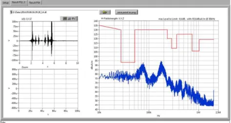
Exemplary results of magnetic fields strength measurement are presented on Fig. 3, 4 and 5. Every time measurement was taking place it was automatically compared with the limit values set
out in technical specifications for each of the direc-tions. Measured data are marked with blue color; red color represents limit values for each of the three directions.
Fig. 3. Exemplary result of measurement in X direction
Fig. 4. Exemplary results of measurement in Y direction
Conclusions
Measurement method and used equipment pro-vided repeatability of results on acceptable level what ensured reliability under condition of regular calibration of whole system according to proce-dures. Further conclusion concerning tests was that it is possible to distinguish some groups of vehicles regarding results types. First of all electric traction vehicles equipped with electro-mechanical traction converters generated significantly less disturbances than the newer generation vehicles equipped with electronic converters. Interference generated by diesel locomotives, which were even smaller and mostly did not exceed disturbance of a background noise. Moreover it was noticed that the higher val-ues of magnetic fields were observed in Y and Z directions. Experience gained so far also indicates that the magnetic fields strength exceedances emit-ted by rolling stock generally concern the meas-urement plane Y. This is due to the mutual influ-ence of magnetic fields generated from rail cur-rents and from rolling stock in this direction. Re-sults gathered during campaign in all countries that participated in the project may contribute to elabo-ration of uniform European measurement method of disturbances from rolling stock. This step will give opportunity to eliminate all sources of ex-ceeded interferences on the stage of approval tests. Facing the general trend of introducing axle count-ers on new railway lines and replacing track cir-cuits with them on modernized ones, the issue of testing the impact of magnetic fields on axle counters is essential and it should be carried out for the entire range of rolling stock that is operating on a rail network. Presented method of measuring magnetic field strength meets the requirements of the technical specifications of theTS 50238-3 and allows clear determination of whether the tested vehicle may affect the operation of the wheel sen-sors and consequently the axle counters. Such ac-tion would eliminate rolling stock that may affect the operation of axle counters, and thus will reduce disturbances in train movements allowing easier traffic management.
LIST OF REFERENCE LINKS
1. Про електромагнітну сумісність електри
-фікованихзалізничнихлінійпостійногоструму
/ І. В. Анохов, М. П. Бадьор, В. І. Гаврилюк,
В. Г. Сиченко // Залізн. трансп. України. – 2000. – № 2. – С. 10–12.
2. Сиченко, В. Г. Допитаннярозробкиактивного фільтра тяговоїпідстанції постійногоструму /
В. Г. Сиченко, В. А. Зубенко, М. П. Бадьор //
Залізн. трансп. України. – 2006. – № 5. –
С. 39–41.
3. Сиченко, В. Г. Дослідження показників якості електричної енергії на тягових підстанціях постійного струму / В. Г. Сиченко // Гірн.
електромеханікатаавтоматика : наук.-техн. зб. / Нац. гірн. ун-т. – Дніпропетровськ, 2008. –
Вип. 81. – С. 53–60.
4. Сиченко, В. Г. Оцінка ефективності функці
-онування пасивних згладжуючих фільт-
рів тягових підстанцій постійного струму /
В. Г. Сиченко, В. А. Зубенко // Вісн. Дніпро
-петр. нац. ун-тузалізн. трансп. ім. акад. В. Ла
-заряна. – Дніпропетровськ, 2008. – Вип. 25. –
С. 63–69.
5. Białoń, A. Badanie kompatybilności elektromag-netycznej taboru z urządzeniami wykrywania pociągu z uwzględnieniem normy EN 50238 / A. Białoń, D. Adamski, P. Pajka // Problemy Kolejnictwa. – 2011. – Z. 152. – P. 43–49.
6. Cholewicki, T. Elektryczne linie długie i układy niejednorodne / T. Cholewicki. – Warszawa : PWN, 1978.
7. CLC/TS 50238-3:2013. Railway applications: compatibility between rolling stock and train de-tection systems. Pt. 3 : Compatibility with axle counters. – 2013. – 16 р.
8. Mariscotti, A. Determination of the Electrical Pa-rameters of Railway Traction Lines: Calculation, Measurement and Reference Data / A. Mariscotti, P. Pozzobon // IEEE Trans. on Power Delivery. – 2004. – Vol. 19. – Iss. 4. – P. 1538–1546. doi: 10.1109/TPWRD.2004.835285.
9. Mariscotti, A. Synthesis of line impedance expres-sions for railway traction systems / A. Mariscotti, P. Pozzobon // IEEE Trans. on Vehicular Tech-nology. – 2003. – Vol. 52. – Iss. 2. – P. 420–430. doi: 10.1109/TVT.2003.808750.
10. Model układu zasilania na torze doświadczalnym w Żmigrodzie / A. Białoń, A. Kazimierczak, W. Zając, G. Skarpetowski // Drives and Supply Systems for Modern Electric Traction in Inte-grated XXIst Century Europe : 4th Int. Conf. (23.09–25.09.1999). – Warszawa, 1999.
11. Mutual design overhead transmission lines and railroad facilities : Report EPRI, EL-646 / Electric Power Research Institute. – Paolo Alto, CA, 1989. – 166 р.
ruchem kolejowym : Praca IK 4430/10. – Warszawa, 2011. – 248 р.
13. Pawlik, M. Control command systems impact on the railway operational safety / M. Pawlik // Нау
-катапрогрестранспорту. – 2015. – № 2 (56). –
С. 58–64. doi: http://dx.doi.org/10.15802-/stp2015/42160.
14. Szeląg, A. Zagadnienia analizy i projektowania systemu trakcji elektrycznej prądu stałego z zastosowaniem technik modelowania i symulacji
/ A. Szelag // Prace Naukowe PW. Seria: Elektryka. – 2002. – Z. 123. – P. 178.
15. Untersuchung der Beeinflussung von Glaisstromkreisen. Frage A 122. Bericht nr 9. Utecht, 1973. – 184 p.
16. Żurkowski, A. Railway operation and transport. Control command and signalling / A. Żurkowski, M. Pawlik // Ruch i przewozy kolejowe. Sterowanie ruchem. – Warszawa, 2010. – Р. 160.
А
.
БЯЛОНЬ
1*,
Д
.
АДАМСКІ
2*,
Ю
.
ФУРМАН
3*1*Залізничнийінститут, вул. Хлопіцького, 50, Варшава, Польща, 04-275, ел. пошта [email protected],
ORCID 0000-0003-1648-0056
2*Залізничнийінститут, вул. Хлопіцького, 50, Варшава, Польща, 04-275, ел. пошта [email protected],
ORCID 0000-0001-5897-579X
3*Залізничнийінститут, вул. Хлопіцького, 50, Варшава, Польща, 04-275, ел. пошта [email protected],
ORCID 0000-0002-4160-3372
УНІФІКОВАНИЙ
МЕТОД
ПЕРЕВІРКИ
ЕЛЕКТРОМАГНІТНОЇ
СУМІСНОСТІ
МІЖ
РУХОМИМ
СКЛАДОМ
ТА
СИСТЕМОЮ
ВИЯВЛЕННЯ
ПОЇЗДА
Мета.Лічильникиосейвсечастішеічастішезастосовуютьсявсистемахвиявленняпоїзда. Датчикколіс є основною частиною кожної системи підрахунку осей. Паралельно з цим, все більш і більш складні залізничнітранспортнізасоби, особливотягові, єпотенційнимджереломперешкод, щовпливаютьнароботу цих систем виявлення поїзда. Це є причиною для перевірки електромагнітної сумісності (ЕМС) між обладнанням зв’язку, зокрема, системами виявлення поїздів, і новими транспортними засобамиу процесі отримання дозволу на їх експлуатацію. Вимірювання заважаючих магнітних полів, що генеруються транспортнимзасобом, повиннестати однимізвипробувань. Методика. Зметою спрощеннятауніфікації застосовуваних методів випробувань були розроблені стандарт EN 50238 та технічна специфікація TS 50238-3. Специфікація визначаєуніфіковані методивипробувань. Проте, необхідно перевірити, чиможуть вони замінити різні методи випробувань, що використовуються в інших країнах Європейського союзу.
Це мета європейського дослідницького проекту, фінансованого з ресурсів мережі TEN-T.
Результати та наукова новизна. Даний проект є частиною більшого проекту по спрощенню та
прискореннюрозгортання системи ERTMS. Однеіздев’ятиекспериментальнихвимірювань, запланованих
врамкахданогопроекту, булопроведеновПольщіІнститутомзалізничноготранспорту. Ключовіслова: сигналізація; сумісність; залізничнийтранспорт
А
.
БЯЛОНЬ
1*,
Д
.
АДАМСКИ
2*,
Ю
.
ФУРМАН
3*1*Железнодорожныйинститут, ул. Хлопицкого, 50, Варшава, Польша, 04-275, эл. почта [email protected],
ORCID 0000-0003-1648-0056
2*Железнодорожныйинститут, ул. Хлопицкого, 50, Варшава, Польша, 04-275, эл. почта [email protected],
ORCID 0000-0001-5897-579X
3*Железнодорожныйинститут, ул. Хлопицкого, 50, Варшава, Польша, 04-275, эл. почта [email protected],
УНИФИЦИРОВАННЫЙ
МЕТОД
ПРОВЕРКИ
ЭЛЕКТРОМАГНИТНОЙ
СОВМЕСТИМОСТИ
МЕЖДУ
ПОДВИЖНЫМ
СОСТАВОМ
И
СИСТЕМОЙ
ОБНАРУЖЕНИЯ
ПОЕЗДА
Цель. Счётчики осей все чаще и чаще применяются в системах обнаружения поезда. Датчик колес являетсяосновнойчастьюкаждойсистемыподсчётаосей. Параллельносэтим, всеболееиболеесложные железнодорожныетранспортныесредства, особеннотяговые, являютсяпотенциальным источникомпомех,
влияющих на работу этих систем обнаружения поезда. Это является причиной для проверки электромагнитнойсовместимости (ЭМС) междуоборудованиемсвязи, вчастности, системамиобнаружения поездов, и новыми транспортными средствами в процессе получения разрешения на их эксплуатацию.
Измерениемешающихмагнитных полей, генерируемыхтранспортным средством, должно стать однимиз испытаний. Методика. С целью упрощения и унификации применяемых методов испытаний были разработаны стандарт EN 50238 и техническая спецификация TS 50238-3. Спецификация определяет унифицированные методы испытаний. Тем не менее, необходимо проверить, могут ли они заменить различныеметодыиспытаний, используемыевдругихстранахЕвропейскогосоюза. Этоцельевропейского исследовательского проекта, финансируемого из ресурсов сети TEN-T. Результаты и научная новизна.
Данный проект является частью более крупного проекта по упрощению и ускорению развертывания системы ERTMS. Одно из девяти экспериментальных измерений, запланированных в рамках данного проекта, былопроведеновПольшеИнститутомжелезнодорожноготранспорта.
Ключевыеслова: сигнализация; совместимость; железнодорожныйтранспорт
REFERENCES
1. Anokhov I.V., Bador M.P., Havryliuk V.I., Sychenko V.H. Pro elektromahnitnu sumisnist elektryfikovanykh zaliznychnykh linii postiinoho strumu [About EMC of electrified railways at DC]. Zaliznychnyi transport Ukrainy – Railway Transport of Ukraine, 2000, no. 2, pp. 10-12.
2. Sychenko V.H., Zubenko V.A., Bador M.P. Do pytannia rozrobky aktyvnoho filtra tiahovoi pidstantsii postiinoho strumu [On the issue of active filter development of DC railway substation]. Zaliznychnyi transport Ukrainy – Railway Transport of Ukraine, 2006, no. 5, pp. 39-41.
3. Sychenko V.H. Doslidzhennia pokaznykiv yakosti elektrychnoi enerhii na tiahovykh pidstantsiiakh postiinoho strumu [Research of quality indices of electricity for DC railway substations]. Naukovo-tekhnichnyi zbirnyk «Hirnycha elektromekhanika ta avtomatyka» [Scientific and Technical Collection «Mining electrical engineering and automation»]. Dnipropetrovsk, 2008, issue 81, pp. 53-60.
4. Sychenko V.H., Zubenko V.A. Otsinka efektyvnosti funktsionuvannia pasyvnykh zghladzhuiuchykh filtriv tiahovykh pidstantsii postiinoho strumu [The effectiveness evaluation of smoothing filters traction substantions DC]. Visnyk Dnipropetrovskoho natsionalnoho universytetu zaliznychnoho transport [Bulletin of
Dnipropetrovsk National University of Railway Transport named after Academician V. Lazaryan], 2008, issue
25, pp. 63-69.
5. Białoń A., Adamski D., Pajka P. Badanie kompatybilności elektromagnetycznej taboru z urządzeniami wykrywania pociągu z uwzględnieniem normy EN 50238. Problemy Kolejnictwa, 2011, Z. 152, pp. 43–49. 6. Cholewicki T. Elektryczne linie długie i układy niejednorodne. Warszawa, PWN, 1978.
7. CLC/TS 50238-3:2013. Railway applications: compatibility between rolling stock and train detection systems. Pt. 3: Compatibility with axle counters. 2013, 16 р.
8. Mariscotti A., Pozzobon P. Determination of the Electrical Parameters of Railway Traction Lines: Calculation, Measurement and Reference Data. IEEE Trans. on Power Delivery, 2004, vol. 19, issue 4, pp. 1538-1546. doi: 10.1109/TPWRD.2004.835285.
9. Mariscotti A., Pozzobon P. Synthesis of line impedance expressions for railway traction systems. IEEE Trans. on Vehicular Technology, 2003, vol. 52, issue 2, pp. 420-430. doi: 10.1109/TVT.2003.808750.
10. Białoń A., Kazimierczak A., Zając W., Skarpetowski G. Model układu zasilania na torze doświadczalnym w Żmigrodzie . Drives and Supply Systems for Modern Electric Traction in Integrated XXIst Century Europe: 4th Int. Conf. (23.09–25.09.1999). Warszawa, 1999.
12. Określenie dopuszczalnych poziomów i parametrów zakłóceń dla urządzeń sterowania ruchem kolejowym: Praca IK 4430/10. Warszawa, 2011. 248 р.
13. Pawlik M. Control command systems impact on the railway operational safety. Nauka ta progres transportu – Science and Transport Progress, 2015, no. 2 (56), pp. 58-64. doi: http://dx.doi.org/10.15802/stp2015/42160. 14. Szeląg A. Zagadnienia analizy i projektowania systemu trakcji elektrycznej prądu stałego z zastosowaniem
technik modelowania i symulacji. Prace Naukowe PW. Seria: Elektryka, 2002, Z. 123, p. 178.
15. Untersuchung der Beeinflussung von Glaisstromkreisen. Frage A 122. Bericht nr 9. Utecht, 1973. 184 p. 16. Żurkowski A., Pawlik M. Railway operation and transport. Control command and signalling. Ruch i przewozy
kolejowe. Sterowanie ruchem. Warszawa, 2010. Р.160.
Prof. V. H. Sychenko, Sc. Tech. (Ukraine) recommended this article to be published

![USE OF ELECTROSPRAY MASS SPECTROMTERY TO STUDY THE INTERACTIONS BETWEEN PARA-SULPHONATO-CALIX[4]ARENE AND A SERIES OF SERUM ALBUMIN PROTEINS](data:image/gif;base64,R0lGODlhAQABAIAAAP///wAAACH5BAEAAAAALAAAAAABAAEAAAICRAEAOw==)