TECHNICAL UNIVERSITY OF CLUJ-NAPOCA
ACTA TECHNICA NAPOCENSIS
Series: Applied Mathematics, Mechanics, and Engineering Vol. 62, Issue II, June, 2019
OPTIMIZATION OF A
γ
-TYPE STIRLING ENGINE PERFORMANCE
BASED ON AN EXPERIMENTAL APPROACH
Adrian Ioan BOTEAN
Abstract: Using a γ-type Stirling engine, with a total cylinder capacity of 20 cm3, this paper aims to
establish the indicated power Pi and the thermal efficiency η according to the temperature gradient between
its component parts (expansion cylinder, radiator and power cylinder). This temperature gradient is controlled by thermal barriers (klingerit gaskets) mounted in four variants for the study.
Key words: gamma Stirling engine, gradient temperature, working fluid, power, speed, thermodynamic cycle, kling erit gaskets, thermal efficiency
1. INTRODUCTION
The advantages of the Stirling engine, regardless of the type, are: low noise during operation, high thermal efficiency, the possibility of using multiple heating sources (including solar, geothermal, etc.). Obviously, there are disadvantages associated with this type of engine among which the following can be listed: unable to change torque and power swiftly, it is low in the power / weight ratio. Among its most successful aplications is the micro combined heat and power (CHP) systems where the power output of the engine is used to generate electicity [1, 2], but also various applications for the recovery of heat [3, 4, 5].
The Stirling engine is made up of a series of multi – dimensional elements whose geometry influences the heat and mass transfer process. A series of complex mathematical models have been developed that allow an analytical approach [6, 7, 8, 9, 10], numerical (CFD for example) [11, 12, 13, 14] and experimental [15, 16] of these processes in order to achieve various prototypes of Stirling engines with superior operating characteristics [17, 18].
The present study has a predominantly experimental approach with an analytical component using Schmidt’s isothermal model [19, 20, 21, 22, 23].
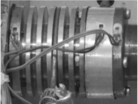
The study presented in the paper [24] showed that the optimal solution results in the Stirling engine cooling, gamma type, is the one that is strictly achieved in the radiator area. This area represents the heat exchanger of the γ-type Stirling engine. The advantage of cooling the radiator is to obtain a high speed [24] and, consequently, a higher developed power [25, 26, 27]. Obviously, there is also a disadvantage that is a higher consumption of the thermal energy. To limit such a disadvantage it is proposed in this study to mount a klingerit gasket (parts 12 and 13 in Figure 1) between the expansion cylinder (part 2 in Figure 1) and the radiator (part 3 in Figure 1); respectively, between the radiator and the base plate (part 5 in Figure 1). For each case, it is intended to determine the indicated power Pi and the thermal efficiency η.
Fig. 1.γ-type Stirling engine studied.
expansion piston (displacer); 2 – the cylinder of the expansion piston / the hot heat exchanger; 3 – radiator / cold heat exchanger; 4 – the con – rod of the expansion piston; 5 – plate; 6 – cylinder of the working piston; 7 – working piston; 8 – the con – rod of the working piston; 9 – the crank of the working piston; 10 – flywheel; 11 – the crank of the expansion piston; 12, 13 – gaskets made of klingerit.
Klingerite is a material made from a mixture of asbestos, rubber and a mineral binder used in the manufacture of gaskets resistant to high temperatures and pressures. Thus, by introducing these gaskets the distributions of the temperature field changes and their evaluation as the primary objective of this study.
According to Figure 2 the constructive characteristics of the Stirling engine are as follows: EP – expansion space, CS – compression space, RC – regenerative channel, VDE=1.0867[cm3] – heat section dead volume, VSD=9.4209[cm3] – displacer swept volume, VDEC=4.8905[cm3] – radiator dead volume, VR=0.785[cm3] – plate channel volume, VDC=0.2019[cm3] – cold section dead volume, VSP=5.0491[cm3] – power piston swept volume.
Fig. 2. Constructive characteristics of the Stirling engine.
The momental expansion volume (VE) is described in equation (1):
1 ∙ 1 1
where α represent the crank angle. This crank angle is defined as α=0 when the displacer is located in the most top position.
The momental compression volume (VC) is described in equation (2):
2 ∙ 1 2 ∙ 1
2
where dα represent phase angle (dα=90o).
The total momental volume is calculated in equation (3):
3
In Figure 3 are plotted the variation graphs of expansion volume VE and compression volume VC according to crank angle α.
Fig. 3. Variation of expansion volume VE and compression volume VC according to crank angle α.
Practically, in this paper, we will define four cases of study of the influence of the temperature gradient on the speed developed by the Stirling engine of the gamma type: variant 1 (wearing the acronym v1) – the expansion cylinder, radiator and base plate are in direct contact (Figure 4); variant 2 (v2) – a klingerit gasket is fitted between the expansion cylinder and radiator and between the radiator and the base plate is direct contact; variant 3 (v3) – between the expansion cylinder and the radiator and between the radiator and the base plate is mounted a klingerit gasket; variant 4: the expansion cylinder and radiator are in direct contact and a klingerit gasket is fitted between the radiator and the base plate.
Fig. 4. The Stirling engine, version 1 (v1) – the expansion cylinder, radiator and base plate are in
In Figure 5 the four study variants are schematically graphically represented.
Fig. 5. Schematic representation of the four study variants.
2. METHODS
The experimental stand, presented in Figure 6, consists of the following elements: 1 - γ-type Stirling engine, 2 – FLIR T400 infrared camera, 3 – data acquisition system HBM SPIDER8, 4 – DT 1236L digital tachometer.
Fig. 6. The experimental stand.
Figure 7 shows the areas where the temperature is measured, indicating in point 1 the temperature which is measured width the FLIR T400 infrared camera; in points 2, 3, 4 and 5 the temperature is measured with Pt100 thermoresistances and at point 6 the temperature is measured with an analogue thermo – manometer, which also monitors the pressure in the cooling circuit. The flow rate in the cooling circuit is 2.5 liters / minute. The graphical interface of the HBM Spider8 data acquisition system is provided by the CatmanEasy – AP (HBM) software according to Figure 8. The graphical interface of the FLIR T400 thermal imaging system is the FLIR Quik Report according to Figure 9. For each of the four constructive options taken into account, three sets of measurements were made. According to each set of measurements, the amount of gas consumed was weighed according to Table 1.
Fig. 7. The Stirling engine, gamma type, studied – the points at which the temperature is monitored.
Fig. 8. Catman Easy – AP graphic interface of the Spider8 data acquisition system.
Fig. 9. The FLIR Quick Report graphic interface of the FLIR T400 thermal imaging system.
Table 1
Fuel consumption [g] V1 V2 V3 V4
Set1 77 58 69 60
Set2 86 60 62 65
Set3 77 59 70 55
Total 240 177 201 180
The obtained results are represented graphically using the Origin 6.0 software through the data mediation function.
3. RESULTS
Figure 10 shows the variation diagram of the TBA (temperature in the burner area) versus time (point 1 in Figure 7).
Fig. 10. Temperature in the burner area, TBA. Figure 11 shows the variation diagram of the TEC (temperature of the expansion cylinder) versus time (point 2 in Figure 7).
Fig. 11. Temperature of the expansion cylinder, TEC. Figure 12 shows the variation diagram of the THZR (temperature of the radiator) versus time (point 3 in Figure 7).
Figure 13 shows the variation diagram of the TCZR (temperature of the radiator) versus time (point 4 in Figure 7).
Figure 14 shows the variation diagram of the TPC (temperature of the power cylinder) versus time (point 5 in Figure 7).
Figure 15 shows the variation diagram of the speed (n) versus time.
Fig. 12. Temperature of the radiator, THZR.
Fig. 13. Temperature of the radiator, TCZR.
Fig. 14. Temperature of the power cylinder, TPC.
The indicated energy Wi per one cycle of this engine, representing the surface area of the indicated diagram (p-V diagram) of the expansion space and the compression space can be calculated using the following coefficients: -swept volume ratio:
0,5359
-expansion volume ratio:
0.1153
-compression volume ratio:
! 0.0214
-temperature ratio:
# $$
where TC represents the compression gas temperature and TE is the expansion gas temperature.
The expansion dead volume (VDE – heat section dead volume) maintain the expansion gas temperature TE and the compression volume (the volume of compression being composed of VDEC – radiator dead volume, VR – plate channel volume and VDC – cold section dead volume) maintain the compression gas temperature TC during the cycle.
The temperature ratio depends on the four study variants taken into account in this paper (according to Figure 4).
The working fluid temperature (air) in the expansion zone (VDE+VSD according to Figure 2) TE is estimated according to TBA (temperature in the burner area) and Table 2 gives the values of this temperature for the three corresponding sets of measurements of the four variants. These values correspond to the final running time of the Stirling engine during the test run (last 600 seconds).
Table 2
Assessment of working fluid temperature in the expansion zone area, TE.
TBA [oC] T
E= TBAmed [oC]
S1 S2 S3
V1 318.65 331.13 326.23 325.33 V2 339.15 335.47 335.64 336.75 V3 350.79 347.97 332.82 343.86 V4 318.22 291.26 302.95 304.14
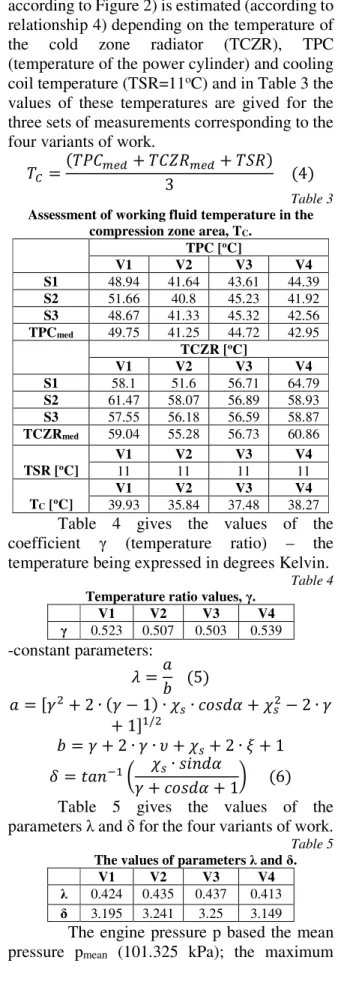
The working fluid temperature in the compression space TC (VDEC+VR+VDC+VSP
according to Figure 2) is estimated (according to relationship 4) depending on the temperature of the cold zone radiator (TCZR), TPC (temperature of the power cylinder) and cooling coil temperature (TSR=11oC) and in Table 3 the values of these temperatures are gived for the three sets of measurements corresponding to the four variants of work.
$ $%&'() $&*+'()3 $,+ 4
Table 3
Assessment of working fluid temperature in the compression zone area, TC.
TPC [oC]
V1 V2 V3 V4
S1 48.94 41.64 43.61 44.39 S2 51.66 40.8 45.23 41.92 S3 48.67 41.33 45.32 42.56 TPCmed 49.75 41.25 44.72 42.95
TCZR [oC]
V1 V2 V3 V4
S1 58.1 51.6 56.71 64.79 S2 61.47 58.07 56.89 58.93 S3 57.55 56.18 56.59 58.87 TCZRmed 59.04 55.28 56.73 60.86 TSR [oC]
V1 V2 V3 V4
11 11 11 11
TC [oC]
V1 V2 V3 V4
39.93 35.84 37.48 38.27 Table 4 gives the values of the coefficient γ (temperature ratio) – the temperature being expressed in degrees Kelvin.
Table 4
Temperature ratio values, γ.
V1 V2 V3 V4
γ 0.523 0.507 0.503 0.539 -constant parameters:
- ./ 5
. #0 2 ∙ # 1 ∙ ∙ 0 2 ∙ #
1 1/0
/ # 2 ∙ # ∙ 2 ∙ ! 1
3 4.5617 ∙ 85
# 19 6
Table 5 gives the values of the parameters λ and δ for the four variants of work.
Table 5
The values of parameters λ and δ.
V1 V2 V3 V4
λ 0.424 0.435 0.437 0.413 δ 3.195 3.241 3.25 3.149
pressure pmax and the minimum pressure pmin are found in the following equations:
; 1 - ∙ cos ;'(<=∙ √1 -30 1 - ∙;'<B∙ 1 - 3
;'C=∙ 1
-1 - ∙ 3 7
where:
;'<B ;'(<=∙ E1 -1 - 8
;'C= ;'(<=∙ E1 -1 - 9
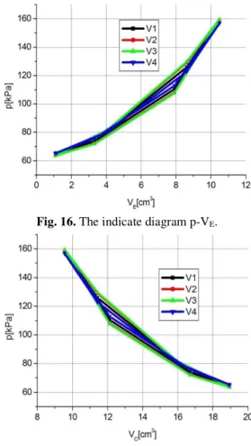
In Figure 16 is shown the indicate diagram of pressure – expansion volume (p-VE) and Figure 17 shows the indicate diagram of pressure – compression volume (p-VC) for the four working variants.
Fig. 16. The indicate diagram p-VE.
Fig. 17. The indicate diagrame p-VC.
Thus, the indicated energy in the compression space (expressed in J) is represented by the following expression:
G H ∙ - ∙ # ∙ ;'(<=∙ ∙ 853
1 √1 -0 10
The indicated energy in the expansion space is represented by the following expression:
G H ∙ - ∙ ;'(<=∙ ∙ 853
1 √1 -0 11
The indicated energy Wi per one cycle of this engine is calculated with the relation:
GC G G 12
The indicated power Pi developed by the engine (measured in W) is expressed by the following relation:
%C GC∙ 5 13
where n represents the speed expressed in revolutions per second or Hz.
Table 6 gives the average speed values n corresponding to the Stirling engine final operating time during the test run (the last 600 seconds).
Table 6
The evaluation speed, n.
n [Hz] nmed
[Hz]
S1 S2 S3
V1 15.29 16.31 13.66 15.08 V2 9.66 11.99 12.7 11.45 V3 15.73 15.34 15.05 15.37 V4 13.23 13.09 13.11 13.14
The thermal efficiency η (expressed as a percentage) of the γ-type engine Stirling is calculated with the following relationship:
I G ∙ 100 14GC
Table 7 gives the indicated power Pi output developed by the engine and the thermal efficiency for the four working variants considered.
Table 7
Assessment of indicated power (Pi) and thermal efficiency (η).
Pi [W] η [%] V1 254.29 47.687 V2 384.94 49.338 V3 569.87 49.656 V4 273.9 48.097 4. CONCLUSIONS
area a lower temperature level, and from an economic point of view this thermal state should be constantly maintained. This can be done by controlling the heat transfer between the radiator and the expansion cylinder, respectively, between the enviroment and the expansion cylinder. Thus, at least two constructive solutions can be identified to meet this goal. A first constructive solution, already implemented in practice, is to insulate the area of the expansion cylinder with various systems that incorporate ceramic materials or mineral wool. A second constructive solution proposed and studied in this paper is to introduce a thermal barrier between the various elements of the γ-type Stirling engine.
From the analysis of the results obtained in this study it follows that variant 3 – v3 – (a klingerit gasket is mounted between the expansion cylinder and the radiator as well as between the radiator and the base plate) is the optimal construction for which the highest speed (n), indicated power (Pi) and thermal efficiency (η) is obtained.
5. REFERENCES
[1] Dawi, S.M.H.W., Othman, M.M., Musirin, I., Kamaruzaman, A.A.M., Arriffin, A.M., Salim, N.A., Gamma Stirling engine for a
small design of renewable resource model,
Indonesian Journal of Electrical Engineering and Computer Science, vol.8, no.2, pp.350-359, 2017
[2] Grosu, L., Dobre, C., Petrescu, S., Study of a Stirling engine used for domestic micro – cogeneration. Thermodynamic analysis and
experiment, International Journal of Energy
Research, 39, pp.1280 – 1294, 2015
[3] Sowale, A., Kolios, A.J., Fidalgo, B., Somorin, T., Parker, A., Williams, L., Collins, M., McAdam, E., Tyrrel, S.,
Thermodynamic analysis of a gamma type
Stirling engine in an energy recovery system,
Energy Conversion and Management 165, pp.528 – 540, 2018
[4] Alfarawi, S., Webb-Martin, M., Mahmoud, S., AL-Dadah, R.K., Thermal analysis of
Stirling engine to power automotive
alternator using heat from exhaust gases,
Energy Procedia 61, pp.2395 – 2398, 2014 [5] Jadhao, J.S., Thombare, D.G., Review on
exhaust gas heat recovery for I.C. Engine,
International Journal of Engineering and Innovative Technology, vol.2, no.12, 2013 [6] Tew, R., Jefferies, K., Miao, D., A Stirling
engine computer model for performance
calculations, National Aeronautics and Space
Administration Lewis Research Center, 1978 [7] Formosa, F., Despesse, G., Analytical model
for Stirling cycle machine design, Energy
Conversion and Management 51, pp.1855 – 1863, 2010
[8] Campos, M.C., Vargas, J.V.C., Ordonez, J.C., Thermodynamic optimization of a
Stirling engine, Energy 44, pp.902 – 910,
2012
[9] Paul, C.J., Engeda, A., Modeling a complete
Stirling engine, Energy 80, pp.85 – 97, 2015
[10] Martaj, N., Grosu, L., Rochelle, P.,
Thermodynamic study of a low temperature difference Stirling engine at steady state
operation, Int.J.of Thermodynamics, vol.10,
no.4, pp.165 – 176, 2007
[11] Salazar, J.L., Chen, W.L., A computational fluid dynamics study on the heat transfer
characteristics of the working cycle of a β –
type Stirling engine, Energy Conversion and
Management 88, pp.177 – 188, 2014
[12] Hachem, H., Gheith, R., Aloui, F., Nasrallah, S.B., Numerical characterization
of a γ – Stirling engine considering losses and
interaction between functioning parameters,
Energy Conversion and Management 96 (2015) 532 – 543
[13] Babaelahi, M., Sayyaadi, H., A new thermal model based on polytropic numerical
simulation of Stirling engines, Applied
Energy 141, pp.143 – 159, 2015
[14] Kuban, L., Stempka, J., Tyliszczak, A., A
3D – CFD study of a γ – type Stirling engine,
Energy 169, pp.142 – 159, 2019
[15] Gheith, R., Hachem, H., Aloui, F., Nasrallah, S.B., Experimental and theoretical investigation of Stirling engine heater:
Parametrical optimization, Energy
[16] Cinar, C., Karabulut, H., Manufacturing
and testing of a gamma type Stirling engine,
Renewable Energy 30, pp.57 – 66, 2005 [17] Scollo, L., Valdez, P., Baron, J., Design and
construction of a Stirling engine prototype,
International Journal of Hydrogen Energy 33, pp.3506 – 3510, 2008
[18] Araoz, J.A., Cardozo, E., Salomon, M., Alejo, L., Fransson, T.H., Development and validation of a thermodynamic model for the performance analysis of a gamma Stirling
engine prototype, Applied Thermal
Engineering 83, pp.16 – 30, 2015
[19] Walker, G., Stirling Engines, Oxford: Clarendon Press, 1980
[20] Schmith, G., Classical analysis of
operation of Stirling engine. A report
published in German Engineering. Union (Original German), vol. XV (1871), pp.1-12, 1987
[21] Hirata, K., Schmidt theory for Stirling
engines, National Maritime Research
Institute, http://nmri.go.jp /env/khirata/, 2019 [22] www.robertstirlingengine.com/theory.php,
2019
[23] Saenyot K., Chamdee P., Raksrithong P., Locharoenrat K., Lekchaum S., Improvement of thermal performance of Gamma – type
Stirling engine, International Conference on
Civil, Mechanical and Material Engineering, AIP Conf. Proc. 1973, 020023 – 1 – 020023 – 5; https://doi.org/10.1063/1.5041407, Published by AIP Publishing 978 – 0 – 7354 – 1680 - 2
[24] Botean, A.I., Influence of the temperature gradient on the speed of a Stirling gamma
engine, Acta Technica Napocensis, Series:
Applied Mathematics, Mechanics, and Engineering, Vol.61, Issue III, 2018.
[25] Botean, A.I., Florescu, M., Glogoveţan, A., Vitan, V., The functional analysis of a gamma
type Stirling engine, Acta Technica
Napocensis, Series: Applied Mathematics, Mechanics, and Engineering, Vol.59, Issue I, 2016
[26] Botean, A.I., Hiticaş, I., Experimental power determination of a gamma type
Stirling engine, Acta Technica Napocensis,
Series: Applied Mathematics, Mechanics, and Engineering, Vol.60, Issue I, 2017 [27] Botean, A.I., Influence of working fluid
pressure on the power of a Stirling gamma
engine, Acta Technica Napocensis, Series:
Applied Mathematics, Mechanics, and Engineering, Vol.61, Issue II, 2018
Optimizarea performanţei motorului Stirling de tip gamma bazată pe o abordare experimentală
Rezumat: Utilizând un motor Stirling de tip gamma, având cilindreea de 20 cm3, ȋn această lucrare se urmăreşte
stabilirea puterii indicate Pişi a randamentului termic η ȋn funcţie de gradientul de temperatură dintre elementele
componente. Acest gradient de temperatură este controlat prin intermediul unor bariere termice (garnituri din clingherit) montate ȋn patru variante de studiu.