Model-Driven Development and Testing – A Case Study
Marc Born1, Ina Schieferdecker1, Hans-Gerhard Gross2, Pedro Santos31Fraunhofer FOKUS, Berlin, Germany
2Fraunhofer IESE, Kaiserslautern, Germany
3Fraunhofer IGD, Darmstadt, Germany
1{born,schieferdecker}@fokus.fraunhofer.de, 2[email protected], 3[email protected]
Abstract
This paper discusses the results and experiences gained from the project Model Driven Development of Telecommunication Systems (MDTS) which is a joint project of three institutes of the Fraunhofer Society. The main goal of the project was to define a model driven software construction process, which enables the integration of system development and system test. It included the provision of a set of supporting tools to increase the level of automation in this process. The developed concepts have been applied in the telecommunication domain using an example application. This application supports mobile workers in
critical industrial domains like aircraft maintenance or chemical production.1
1.
Introduction
The provision of efficient techniques and tool support for development and engineering of distributed systems is a key enabling factor for the further evolution of Information Technology. Distributed systems consist of components that are spread over networks, and they have to cope with concurrency, autonomy, synchronization, and communication aspects. Future CASE tools will support all phases of the development process – from requirement capturing over design and implementation to integration, test and deployment. Code generation based on object oriented design models leads to reusable, executable components. Such components integrate runtime-environment- and middleware-platform-technology-dependent aspects with the enterprise-specific object oriented design model. Using the same design models, particular code generators can be applied to derive components for different deployment and runtime infrastructures. In a manufacturing step, components will be assembled to build up the running solution – even this can be supported by generated deployment descriptors. MDTS integrates object oriented design and component based manufacturing in a model-centric approach.
The primary idea of model-centric, component-based development is to assemble applications from individual compositional units that are represented in an abstract notation or model, such as the UML [6]. These models are refined and amended until they can be turned into an implementation or until an appropriate existing implementation is found. All steps are ideally supported through a tool-suite that com-prises automatic generators and model transformation. The vision is to elevate the more traditional approach of programming with high-level languages onto much more abstract levels that deal on the user surface with the manipulation of graphical representations. Many different notations and methods have been developed for the creation of specification and design of component based software systems such as the Rational Method, Fusion or Catalysis. In this project the KobrA method is used which is based on many technologies adapted from these notations and supported by the Model Driven Architecture (MDA) approach. The KobrA Method defines the products and processes involved in creating and apply-ing a framework of KobrA components. The method is based on the fundamental principle of cleanly separating concerns, such as product and process. The result is an approach that is highly-architecture centric, incremental and scaleable. The MDTS project extends the existing KobrA method, which is adapted for information systems so far only, with concepts, diagrams and items, which are specific for distributed, real-time and telecommunication systems. Here, above all, concepts of the Unified Modeling
1 This work has been partially supported by the BMBF project MDTS on Model-Driven Development of Telecommunication
Language (UML) are at the focal point, which support a continuous representation of a system on all abstraction levels and provide an automatic code and test system generation. Together with the system design, test models and test specification are developed to support an immediate and continuous testing of the system during its design stages: from the initial requirements via prototypes down to the various system releases. The test design is tightly coupled with the system design and reuses where possible the information provided in the system design.
Section 2 introduces the overall development method that acts as a framework to all subsequently intro-duced concepts and technologies. It can be seen as a generic guide for model-driven, component-based system developments that suggests what a development team is supposed to do, when and how they are supposed to do it, along the development activities of a system. Section 3 concentrates on how do-main-specific notations can be derived from a meta-model, and how they can be applied in their target domains. Additionally, it introduces the used case study. Section 4 briefly explains how an application can be implemented and deployed, and Section 5 how it can be validated through model-based test development and execution techniques. Section 6 concludes the paper with a summary and outlook.
2.
Overall Approach
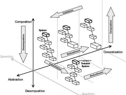
Model-driven development follows the traditional divide-and-conquer approach of defining a system-architecture. The entire system is broken into consecutively more and more concrete and smaller units that can be individually tackled. These are implemented, and then composed to make up the final sys-tem. This represents a top-down approach to system design. In contrast, in its purest form, component-based development represents a bottom-up approach to system construction in which appropriate individual units are identified, selected and assembled, and then integrated to form a new application. In practice, however, a pure bottom-up approach will quite likely lead to a system that is not conformant with its original user-level requirements, so that both approaches are typically intermingled. The KobrA method [1] provides such a combination of the two approaches into a powerful generic framework for model-driven and component-based system engineering. It propagates a spiral model that is carried out in three dimensions (Figure 1): Composition Specificity Concretization Abstraction Embodim ent De co mp o sit io n C o mp o sit io n Validation Decomposition Genericity Instantia tion System <<variant>> Testable System Embodim ent Composition Specificity Concretization Abstraction Embodim ent De co mp o sit io n C o mp o sit io n Validation Decomposition Genericity Instantia tion System <<variant>> Testable System Embodim ent
Figure 1: Three development dimensions of the KobrA method.
The test software is modeled and developed in exactly the same way as the functional software. Abstract testing artefacts are derived and modeled from the existing UML suite for each of the components (boxes
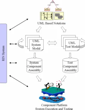
tic basis for an iterative development of system and test models in UML. Code generation tools [11][13] derive component assemblies from these models, which are deployed onto a CORBA component plat-form [12]. The system and its tests are perplat-formed on this platplat-form allowing the analysis and evaluation of the final system in its target environment. An example application – the RIN system [14] – was used as a case study throughout this process [1].
Figure 2: Integrated System and Test Development.
The next two sections describe in more detail how the individual boxes are treated during the development activities, while Section 5 extends the overall approach with the technologies that are used for test modeling, development and execution.
3.
Modeling
Modeling a system requires a clear and precise definition of the used modeling concepts and their relations. This definition of modeling concepts (the so-called concept space) will most likely contain items that are specific to the considered application domain. In the case of MDTS, this is the telecommunication domain. So, for the definition of the concept space the goal was to take telecommunication specific requirements into account. Such requirements are the support for continuous media communication or the consideration of non-functional aspects like Quality-of-Service. In addition, the concept space should not only contain the concepts for the system-design but also for the test of the system. For the definition of such a concept space we used the Meta Object Facility (MOF). The MOF allows the definition of modeling concepts independently of any notation for the presentation of models. They are also independent of any technology used to further transform the models either into other models, or into code or other artifacts like descriptors or documentation.
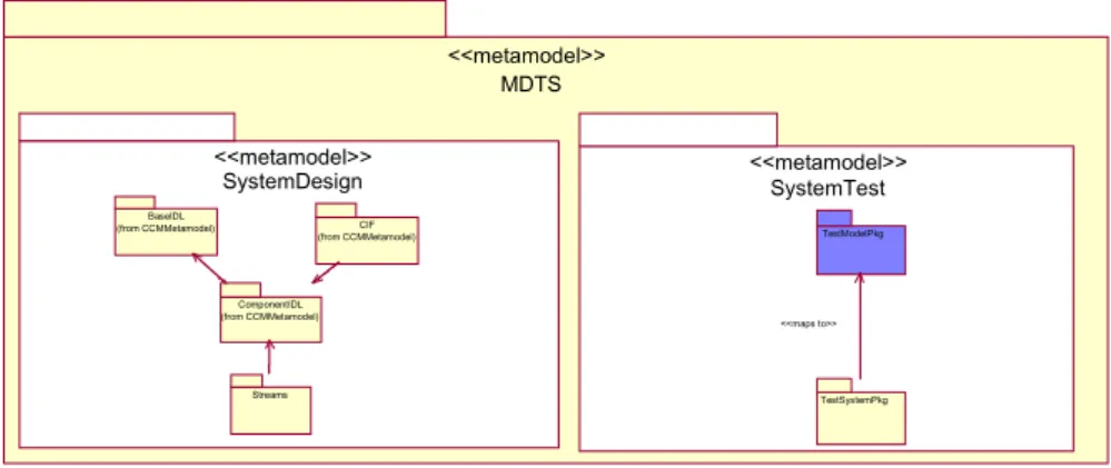
Figure 3 shows the MDTS MOF-based meta-model with its two parts for design and test. The design part is based on the meta-model for CORBA which has been extended with concepts for component-based development and configuration. Furthermore, domain specific requirements have lead to concepts to support stream-based communication between components, for instance.
MDTS <<metamodel>> SystemDesign <<metamodel>> SystemTest <<metamodel>> Streams ComponentIDL (from CCMMetamodel) CIF (from CCMMetamodel) BaseIDL
(from CCMMetamodel) TestModelPkg
TestSystemPkg <<maps to>>
Figure 3: MDTS Meta-model
The meta-model has been used to generate model repositories with available MOF tools [11]. In order to represent models we have defined notations. These notations are based on the UML and, they have been implemented as UML profiles, and were connected to the repositories. The meta-model and notations have been submitted to the OMG and will become standards.
In order to be sure that the concepts are appropriate for the telecommunication domain, we have tested them with an example: The MASP (Mobile Applications Supportive Pals) field assistant tool, which supports working floor maintenance staff in their everyday working tasks. This communication system hosts multiple communication devices that are interconnected through a radio network and controlled and supported by a number of desktop working places. The desktop working places help the mobile maintenance staff to achieve their tasks and provide additional information. They can guide a worker through complex tasks by looking at the video signals from the worker’s video facility, as well as the monitored resource information, give advice to the worker through the audio device, and provide additional information, for example the download of user manuals or video-based repair guides. Each of the communication devices has defined capabilities that are made public to all the other devices through the RIN (Resource Information Network), a subsystem of the MASP Field Assistant Tool.
Every device that is part of the RIN network will have a RIN client, a RIN server and a number of RIN plug-ins installed. The server controls the resource plug-ins and clients on other devices, such as desktop workstations communicate with the RIN Server. The client gets the information from the associated device’s RIN server. All the devices within the range of the communication system can, before they communicate, retrieve information from their associated nodes as to which resources they are capable to read and set at the moment. In that way, the individual nodes are never overloaded with data that they cannot process as expected. For example, the video application of a desktop station may determine the current memory state of a handheld device and decide according to that information whether it can send colored frames or only frames in black and white, it may also reduce the frame rate, or ask the handheld device to remove some of its unused applications from its memory. These decisions depend on the profile of the user and the priority of the applications that use the resource information network.
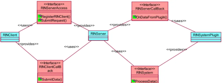
As shown in Figure 4, the RIN system consists of three primary components: RINClient, RINServer and RINSystemPlugin. The RINClient component requires host system information like „system memory state“ or „system power state“. It connects to the RINServer component for such requests. For this connection RINClient uses (“uses”) the provided (“provides”) RINServer’s interface RINServerAccess. The component RINClient provides also an interface RINClientCallBack. This interface is used by the RINServer in order to transmit required information to the RINClient back. The RINServer component resides on each node in the network. It receives the client requests (via RINServerAccess) and transmits these to the appropriate plug-in component RINSystemPlugin. This provides the interface RINSystem for
RINServerAccess RegisterRINClient() SubmitRequest() <<Interface>> RINClient <<uses>> RINClientCallB ack SubmitData() <<Interface>> <<provides>> RINServerCallBack OnDataFromPlugIn() <<Interface>> RINSystemPlugIn <<uses>> RINServer <<provides>> <<provides>> <<uses>> RINSystem ProcessData() <<Interface>> <<provides>> <<uses>>
Figure 4: RIN system components
4.
Coding and Execution
Based on the definitions of the MDTS modeling concepts in terms of a meta-model, a set of code generation rules have been defined and implemented. With the code generator concrete models that conform to the conceptual foundation of MDTS can be mapped onto software components. These software components can be deployed, configured and executed within an extended CORBA Component Model (CCM) platform. This platform is semantically similar to the container concept introduced as a runtime environment for CORBA Components, but extends it with respect to several aspects. Such aspects comprise runtime support for representations of interfaces that contain interaction elements of different interaction kinds, and the support for continuous media interaction. The runtime environment provides a common instantiation and resolution mechanism for components as well as a complete support for communication channels for the different types of interactions. These communication channels are based on plain CORBA for operational interaction elements, on the Notification Service for signal interaction elements, and on a proprietary continuous media delivery platform for continuous media interaction elements.
Generally, the concepts of MDTS are not only mapped to definitions of interfaces that are supported by a particular component, but also to implementation language specific code skeletons of implementation artifacts, descriptions of the state of such artifacts and programming language specific code that form the runtime environment for a component. Here, the realization of the component behavior is de-coupled from the actual activation procedures for the implementation artifacts. The flexibility of this approach also allows the implementation class definition to be independent from the implied interface definition, in a way that an implementation artifact may only implement parts of the set of interaction elements that are provided by a defined interface. Whereas for the operational and signal-based interactions standard CORBA mechanisms are used, the elements of continuous media interactions are mapped onto a multimedia content composition and delivery mechanism using H.323 [10].
The code generation produces executable, deployable software components. These software components contain representations of component types. The component developer still needs to provide the business logic that is implementing the behavior of component types. The code generation tools use C++ as the target language. A number of supporting tools has been developed as well, notably a configuration tool that utilizes the advantage of software components to support a common management view, especially for configuration purposes, based on the port concept and common instantiation principles. Within MDTS we have also developed a consistent tool chain for the entire deployment process including support for managing and monitoring running applications. An assembly package (i.e. a component assembly) contains the software components and its requirements on potential target environments. The required descriptors are completely generated out of the application design model. This acts as input to the deployment process. Another input is the description of the actual configuration of a concrete target environment into which the assembly will be deployed. The deployment process may be done automatically or manually controlled by the user. If all requirements of all components of the assembly are fulfilled by the properties of the target environment, the assembly can be installed, instantiated and configured. The running assembly can be managed and monitored by management and monitoring tools [5].
In case of our sample application, the interfaces of the RINClient, RINServer and RINPlugin modules have been modeled in CCM, while the business logic of the RIN network, developed previously to use COM/DCOM Technology, could almost entirely be dropped into the generated source code, without major changes, which shows the ease of use of our code generators.
5.
Testing
Testing the correct functioning of individual client/server interactions against the specified contract requires a verification that a system of components as a whole will behave correctly. Built-in contract testing is based on the notion of building contract tests into components so that they can validate that the servers to which they are "plugged" dynamically at deployment time will fulfill their contract. Consideration of built-in test artifacts begins early in the design phase as soon as the overall architecture of a system is developed and/or the interfaces of components are modeled. Built-in test can be and should be derived from the system model and should be developed in an integrated manner together with the system design, system model and system implementation.
The UML testing profile (U2TP [8]) specifically addresses typical testing concepts in model-based development. U2TP is an extension of UML 2.0 that is based on the UML meta-model. It defines a modeling language for visualizing, specifying, analyzing, constructing and documenting the artifacts of a test system. The testing profile particularly supports the specification and modeling of software testing infrastructures. It follows the same fundamental principles of UML in that it provides concepts for the structural aspects of testing such as the definition of test components, test contexts and test system interfaces, and behavioral aspects of testing such as the definition of test procedures, test setup, execution and evaluation. The core UML may be used to model and describe testing functionality since test software development can be seen as any other development for functional software properties. However, as software testing is based on a number of special test-related concepts these are provided by the testing profile as extensions to UML. The concepts are mainly concepts for test architectures, test behaviors and test data.
If the built-in tests have been generated and specified in the UML 2.0 Testing Profile (U2TP), their executable versions can be generated with mappings [5] towards existing test execution environments based e.g. on TTCN-3 (Testing and Test Control Notation) [12], which is a widely accepted technique for testing in the telecommunication and data communication domain. TTCN-3 is a test specification and implementation language that can be used to define test procedures for black-box testing of distributed systems. The constituents of a TTCN-3 test specification are derived from the U2TP built-in test specification including, e.g. test type and data definitions and the definition of test behavior and test cases. A built-in test component is equipped with the component-specific executable versions of the TTCN-3 tests together with the access to a TTCN-3 runtime environment for test execution.
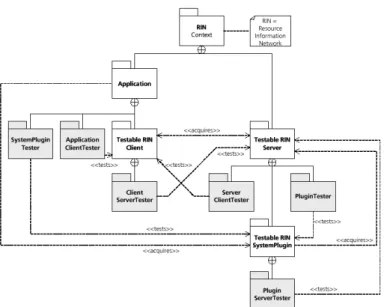
The built-in test architecture for RIN is shown in Figure 5. The RIN system provides the backbone for a highly flexible communication system that can handle many heterogeneous mobile devices. It means that the individual devices may be based on the full variety of available platforms, with differences in hardware, operating systems and applications. It means that in the same application quite a number of different platforms may be used on which the RIN system is operating. The RIN system must therefore be tested on each platform and for each configuration. This is a platform test that checks the correct connection to the underlying middleware platform. An additional feature is the provision of different system plug-ins according to how a device is equipped with hardware. For testing it means that different types of plug-in components may be added on different platforms. And they must all abide by the contract that the server is implementing for communicating with these plug-ins.
Figure 5: RIN built-in test architecture
The tests are all situated on a lower-level of abstraction, the network or communication level. An additional application-level test assures that the application retrieves the right information from the respective plug-ins. In other words, a number of high-level requests are sent from the application to the plug-in (via the server). Each application will be augmented with a tester component for each plug-in that it is accessing. All tests are solely based on the contract testing approach [2]. Figure 5 displays the organization of the RIN system with built-in contract testing. The test cases for the server cover for example the registration of clients (test case Registering), requests or “bypass” requests from clients (test case Requesting), or releasing the resources (test case Releasing). The set of test cases, i.e. the test suite, for the RIN server together with the execution order of these tests is depicted in Figure 6. The test cases Requesting and Releasing are only performed if the test case Registering has been successful. The details of the Requesting test case are shown in Figure 6. It is derived from the behavioral model of the RIN server. sd RINServerBIT [verdict == fail] [verdict == pass] verdict = Registering ref Requesting ref «testSuite» RINServerBIT isInState (State) : Boolean isRegistered (Client) : Boolean MessageInServer (TestActive, Message) : Boolean isActive (Plugin) : Boolean « timer » t
«testCase» +Registering() : Verdict «testCase» +Requesting() : Verdict «testCase» +Releasing() : Verdict
Releasing ref sd RINServerBIT sd RINServerBIT [verdict == fail] [verdict == pass] verdict = Registering ref Requesting ref Requesting ref ref «testSuite» RINServerBIT isInState (State) : Boolean isRegistered (Client) : Boolean MessageInServer (TestActive, Message) : Boolean isActive (Plugin) : Boolean « timer » t
«testCase» +Registering() : Verdict «testCase» +Requesting() : Verdict «testCase» +Releasing() : Verdict
Releasing ref Releasing ref ref sd Registering RINClient «sut» RINServer Register(validClient) «validationAction» pass «sut» RegisteredClients {readOnly} Client validClient; { validClient.authorized(username) == true and
validClient.callback(address) == true } add(validClient) t(2.0) waiting registered sd Registering sd Registering RINClient RINClient «sut» RINServer«sut» RINServer Register(validClient) Register(validClient) «validationAction» pass «sut» RegisteredClients «sut» RegisteredClients {readOnly} Client validClient; { validClient.authorized(username) == true and
validClient.callback(address) == true } add(validClient) add(validClient) t(2.0) t(2.0) waiting registered
Figure 6: Server built-in tests – Registering test case.
These tests are translated to TTCN-3. The TTCN-3 tests are detailed enough for the generation of executable code, in our case Java. The compiled Java byte code is deployed and executed in a TTCN-3 execution environment.
6.
Summary and Outlook
The growing variety of equipment and networking infrastructures in the information and telecommunication domain, added to the widespread interest in mobile usage, leads to a rising demand for software components, which are able to run and co-operate under heterogeneous and varying conditions. The requirements for the development of such software components regarding adaptability, stability, reliability, and performance are increasing permanently and efficiency considerations during the development process are of outmost importance. The MDTS project aims on the provision of model-based development techniques that are suitable to cover the above requirements. Model-model-based in that
context means that code modules of software components are generated from models to a high extend. The main achievements of MDTS as discussed in this contribution are:
• the provision of a component-oriented, customized development process for model-based development.
• the definition of modelling concepts that are suitable to model telecommunication systems, and concepts for the development of test suites for these systems.
• the implementation of code generators for the automatic generation of software and test components.
• the verification of the process, the concepts and the generators within the development and implementation of an application system that involves technology from the mobile computing domain.
The MDTS results are of great value to enterprises and organisations, which develop software for distributed telecommunication systems. The application of these methods targets highly mobile users, who require permanent and ubiquitous access to information and services during their work. Examples of prospective users are field workers in industrial context such as in chemical plants or aircraft maintenance. Future research will primarily focus on the extension of the concept space to include behavioural descriptions, the simulation of a model prior to its implementation based on the behaviour description, and the extension of the execution platform to support enhancements of concepts for component adaptation.
Acknowledgement
This work has been partially funded by the German Federal Department for Education and Research under the MDTS project (http://www.fokus.fhg.de/MDTS).
References
[1] Atkinson, C., et al. Component-based Product Line Engineering with UML. Addison-Wesley, 2002. [2] Gross, H.-G., Atkinson, C., Barbier, F: Built-in Contract Testing for Component-based Development. In:
Business component-based Software Engineering, Barbier (ed.), Kluwer 2003.
[3] Gross, H.-G. Testing and the UML – A Perfect Fit. Fraunhofer IESE Report 110.03E, 2003.
[4] T. Ritter, M. Born, P. Santos: Rapid engineering of collaborative and adaptive multimedia systems on top of CORBA Components. Kommunikation in verteilten Systemen (KiVS 2003); Leipzig Germany; 2003.
[5] I. Schieferdecker, Z. R. Dai, J. Grabowski, A. Rennoch: The UML 2.0 Testing Profile and its Relation to TTCN-3, IFIP 15th Intern. Conf. on Testing Communicating Systems - TestCom 200TTCN-3, Cannes, France, May 2003. [6] OMG. UML 1.4 with Action Semantics, Final Adopted Specification, OMG document ptc/02-01-09, January
2002.
[7] OMG: UML Profile for CORBA Specification,V1.0, Final Adopted Specification, 2000. [8] OMG: The UML 2.0 Testing Profile, Final Adopted Specification, ad03-03-26, July 2003
[9] ETSI ES 201 873 – 1, v2.2.1, "The Testing and Test Control Notation TTCN-3: Core Language ", Oct. 2002. [10]ITU-T: H.323 - Packet-based multimedia communications systems, 2003.
[11]IKV++: MOF based Modelling and Generation tools, http://www.ikv.de/content/Produkte/medini.htm [12]Open Source: The Qedo Tool Suite (a CCM implementation): http://qedo.berlios.de
[13]Testing Technologies: TTCN-3 based tool series. http://www.testingtech.de/products [14]RIN system: Fraunhofer IGD, Darmstadt, Germany, http://www.igd.fraunhofer.de