A NOVEL TECHNIQUE FOR NON-INTERUPPTED REPLACEMENT
UPS SYSTEM WITH THE INTEGRATION OF PORTABLE TRANSFER SWITCH (PTS)
NORMALINA BINTI RASDI
A project report submitted in partial fulfillment of the
requirement for the award of the
Degree of Master of Electrical Engineering
Faculty of Electrical and Electronic Engineering
Universiti Tun Hussein Onn Malaysia
TABLE OF CONTENT
CHAPTER TITLE PAGE
ACKNOWLEGDEMENT i
ABSTRACT ii
ABSTRAK iii
TABLE OF CONTENTS iv
LIST OF TABLE v
LIST OF FIGURE ix
LIST OF SYMBOLS AND ABBREVIATIONS xi
LIST OF APPENDICES xiv
CHAPTER 1
INTRODUCTION
1.1 Background of Study 1
1.2 Problem Statement 2
1.3 Objectives of the Study 3
1.4 Scopes of Study 4
1.5 Significance of study 4
1.6 Expected Results 5
CHAPTER II LITERATURE REVIEW
2.1 Introduction 7
2.2 Related Work 7
2.3 Overview of UPS Topologies 11
2.3.1 Passive Standby UPS 11
2.3.2 Line Interactive UPS 12 2.3.3 Double Conversion UPS 13 2.3.4 Double Conversion UPS with Redundancy 15
2.4 Transfer Switch 17
2.4.1 Automatic Transfer Switches (ATS) 18 2.4.2 Solid State Transfer Switch (SSTS) 19
2.5 Power Quality 25
2.5.1 Power Quality Disturbance 25 2.5.2 Power Quality Standard 30
CHAPTER III METHODOLOGY
3.1 Introduction 33
3.2 Design a new UPS and PTS 34
3.2.1 Design a new UPS 35
3.2.2 Design a Portable Transfer Switch (PTS) 37
3.2.3 Load Requirement 39
3.3 Simulation in PSCAD 42
3.3.1 Process Flow 42
3.3.2 Simulation Circuit 43
3.4 Hardware Development 44
3.4.1 Process Flow 44
CHAPTER IV RESULTS AND ANALYSIS
4.1 Introduction 47
4.2 PTS Pre-inspection Results 47
4.3 Simulation Results 48
4.4 Hardware Results 51
CHAPTER IV CHANGEOVER PROCEDURE
5.1 Introduction 55
5.2 Removal of UPS 55
5.2.1 Stage 1 58
5.2.2 Stage 2 59
5.2.3 Stage 3 61
5.2.4 Stage 4 62
5.2.5 Stage 5 63
5.2.6 Stage 6 65
5.2.7 Stage 7 67
5.2.8 Stage 8 69
5.3 Installation of UPS 71
5.3.1 Stage 1 71
5.3.2 Stage 2 72
5.3.3 Stage 3 73
5.3.4 Stage 4 75
5.3.5 Stage 5 77
CHAPTER V CONCLUSIONS
6.1 Introduction 81
6.2 Conclusion 82
6.3 Future Work 84
REFERENCES 86
CHAPTER 1
INTRODUCTION
1.1 Background of Study
Mass-produced Uninterruptable Power Supply (UPS) first appeared on the market in the 1970s, addressing the need on continuity and quality of supply of electrical power to the large computers system [1]. In the 1980s, UPS covers a diverse range of products and then UPS became one of vital electrical equipment in various sectors. Nowadays, UPS was not only used in power plant, petrochemicals, and oil and gas sector but are also in small or home offices (SOHO). In manufacturing sector, UPS was specially designed to provide continuous and high quality power to the critical process loads, such as Distributed Control System (DCS), Programmable Logic Controller (PLC), critical process alarms, Safety Interlock and/or Shutdown system (SIS), Advanced Process Control (APC) computers, custody transfer flow meters, process stream analyzers, gas detection system, fire protection system, critical telephone circuits, and emergency lighting [2]. In the face of main power failure due to whatever reason, UPS system is expected to deliver the required power to the critical process load without any interruption or break in the supply.
committee, later adopted the IEC standard to ENV 500091-3. Both standardization bodies decided that there are three (3) types of UPS topologies which are Passive Standby, Line Interactive and Double Conversion [1]. Their complexity are different, as well as their performance. The selection of UPS topologies and its configuration for each installation varies, determined by the balance between cost and performance, power rating and also the acceptable level of the various form of risks.
Sometimes, N + 1 redundancy are used in the UPS system to handle contingency of UPS unit failure [3,4]. By having two UPS connected in parallel mode will increase the reliability of the power supply. However, each UPS in the parallel UPS system must be able to function individually to attain true redundancies which include better stability and robustness.
1.2 Problem Statement
IEC 62402 defines obsolescence as the transition from availability, from the original manufacture, to unavailability and permanent transition from operability to non-functionality due to external reasons [5].
Most industries are now facing the challenges related with an increased quantity of aging equipment with several installed equipment already reaching 25 to 40 years of service or manufacture life. Even though the equipment are operating at low load and it is anticipated to have longer useful life, but unavailability of spare part support and mergers of original equipment’s manufacturer (OEM) will lead the parts or equipment in obsolescence status. Obsolescence issue is unavoidable for industrial equipment especially instrumentation equipment which installed in the 1980s’. Equipment can become obsolete due to several factors as below:-
a) Advancement of technology, evolving or design improved,
b) Lack of feasible market for the replacement required for failure parts, c) Manufacture failed to keep cost in control relative to the cost of their
Availability of spare parts replacement, availability of support from OEM and equipment performance in service are the mains factors to determine HIGH, MEDIUM or LOW categories of next maintenance action. Equipment which is classified HIGH is having low score on the main factors and equipment requires an immediate maintenance action such as upgrading or replacement to ensure operational continuity and reliability. The MEDIUM category corresponds to aging equipment but still supported by OEM which requires detail monitoring and management plan especially on spare part support. For the LOW categories, only requires continuous monitoring at certain interval.
Existing UPS are subjected to the obsolescence’s issue due to OEM is no longer in business. Users from various sectors are left without support in term of spare part and technical support requirements. Existing UPS performance are fall in HIGH category as the performance of the UPS is poor. Few tripping happen and one of the tripping initiated the Plant Emergency Shutdown System. Monitoring on the abnormalities of the UPS was performed as per Appendix A. Thus, UPS replacement is one of action taken to overcome above problem. What is more, the load connected to the existing UPS are very critical and need the UPS replacement work conducted without power interruption to the load. It is a difficult work especially when it involves AC System. Compared to DC UPS System which requires controlling only voltage parameter, AC UPS System requires additional parameters to be monitor which are phase, phase rotation and phase difference [7].
In most industries, UPS system placed indoor, in Electrical Substation where space to install the UPS unit is a premium. Hence, installation of new UPS on the same foot print is unavoidable, this condition makes an AC UPS replacement work exceptionally challenging. At the same time, AC UPS replacement work must be executed safely to the personnel at site, surrounding equipment and environment.
1.3 Objectives of the Study
The objectives of this research were focused on
b. Design a portable transfer switch (PTS) to provide a temporary power supply to the critical load during UPS replacement work.
c. To prepare the changeover procedure using PTS in order to attain an interruption free to the connected load during UPS replacement work.
1.4 Scope of Study
The scopes of study were focused on:
a. To comprehend on the configuration and operation of UPS for each topology, b. To study and analysed performance of switching equipment, kind of
disturbance in power supply and requirement of UPS load,
c. To propose a circuitry of portable transfer switch (PTS), this will act as a temporary power supply to the critical load,
d. To verify the switching equipment circuitry by performing simulation using Power System Computer Aided Design (PSCAD),
e. To prepare the switching procedure using PTS for Double Conversion with redundancy AC UPS replacement.
1.5 Significance of Study
1.6 Expected results
This research will disclose the potential of PTS as valuable temporary power supply and SSTS as appropriate switching equipment for critical load. In addition, able to identified safe and apposite method to set up the PTS into UPS system and using internal SSTS for the changeover process are the main point that contributed to the expected results. Therefore, changeover process from main power supply to the alternate power supply can be conducted smoothly and safely. At the same time, this project contributes on cost saving to the plants as PTS parts are inexpensive and easily available in market. However the most important saving is recovering cost from the consequences due to interruption of the critical load such as production line go out of control, creating hazardous situation for on-site personnel and expensive material waste. The value might reach more than the expectation.
1.7 Thesis Structure
This project thesis is organized as follows:-
Chapter 1 covers the background of the study, problem statement, objective of the project, project scope, significance of project and expected results from the research and experiment.
Chapter 2 presents the literature review of previous case study on the UPS replacement without interruption, SSTS performance and parallel inverter. Information on the UPS topologies, switching technology and power quality disturbance were enlightened in details in this chapter.
Chapter 4 report and discuss on the result obtain from pre-test of PTS, simulation of switching equipment using PSCAD and hardware output. The results from simulation and hardware output were compared to identify the appropriate switching equipment for the changeover process.
Chapter 5 explicates the changeover procedure for the UPS replacement work, starts from removal of existing UPS to the installation of new UPS. The procedure is very important reference document to ensure correct step are conducted at each stage so that changeover conducted without interruption to the load.
CHAPTER 2
LITERATURE REVIEW
2.1 Introduction
This chapter starts with literature review of previous case study on the UPS replacement without interruption. Understanding aforementioned researchers are important as guidance for this study to move on. Literature review on UPS topologies and transfer switch are discussed here in. More detailed information on transfer switch was also presented and literature review on power quality was deliberated in last section.
2.2 Related Work
to that, many studies were conducted and implemented around the world to achieve high availability and reliability of UPS system. At the same time, several designs were also established to ensure interruption free during UPS replacement work if require system upgrading.
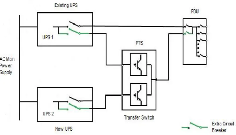
Interruption free UPS replacement work was conducted in NTT Facilities, Inc, Japan using portable transfer switch (PTS) which consist of insulated gate bipolar transistor (IGBT), magnetic coil (MC), phase detector, control block, button switch and pilot indicator. Replacement work was executed by Yoshida et al., (2003). Single line diagram of the replacement work is shown in Figure 2.1 below. The decent features for above design are automatic phase detection and transfer function, checking the connected terminal phase function and portability.
[image:13.595.121.523.455.686.2]The replacement procedure was established to ensure interruption free to the load can be materialized. The results shown, transfer time is about 40 microsecond and disturbance free within the transfer time. However, extra circuit breaker is required in existing UPS, new UPS and power distribution unit (PDU). Additional cables are also prerequisite materials for the UPS replacement work. Shown in Figure 2.2 were current and voltage waveform of the UPS and power distribution unit during the changeover process.
Figure 2.2 Current and voltage waveform [7]
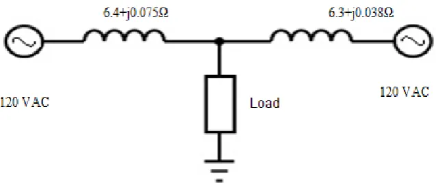
Anaya-Lara, O. and Ache, E (2002) studied on the effectiveness of three power controllers namely distribution static compensator (D-STATCOM), the dynamic voltage restorer (DVR) and the solid state transfer switch (SSTS). PSCAD/EMTDC was used to perform the modelling and analysis for above controller. The aimed of extensive simulation is to enhance the reliability and quality of power flows in low voltage distribution network. For SSTS as shown in Figure 2.3, experiments without SSTS and with SSTS were conducted to access the effectiveness of SSTS. Result shown that with SSTS the voltage at the load is driven back to the pre-fault value very rapidly right after fault occurred as shown in Figure 2.4.
[image:14.595.128.514.576.743.2]Figure 2.4 Voltage of waveform at the load when SSTS is in operation [8]
Tuladhar, A. et al (1997), developed a control technique to operate two or more single phase inverter modules in parallel without interconnection. The main ultimatum of parallel inverter is to achieve high reliabilities and flexibility which making the UPS system very noteworthy to user as it can be used in various application.
The proposed system is wireless system which each UPS module having own control loops to allow independent inverter to share load in proportion to their capacity. AC power line is the only interconnection between the two modules. When there is load change, each inverter will respond automatically, proportionate to its power rating. It can be achieved by introducing artificial droop in the inverter frequency and voltage.
Simulation was performed on two inverter modules which in parallel configuration. Each module are having different power rating, connected together and supply power to the nonlinear load as seen in Figure 2.5. From the simulation, the real power (P) is perfectly shared between the modules while the reactive power (Q) sharing is not strictly proportional [9]. The discrepancy of the reactive power (Q) is because on the line impedance between the inverter modules.
Based on above related work, the researcher make an excellent effort to design a switching circuit, changeover procedure, perform simulation on power controller to ensure no issue on voltage and current can be seen by sensitive load.
The approaches of this study are adapting changeover procedure which was conducted at NTT Facilities, Inc., Japan and simulation based on studied conducted on SSTS performances.
Figure 2.5 Two inverter modules in parallel configuration
2.3 Overview of UPS Topologies
IEC 62040-3 defined three types of UPS topologies, classified in term of their operation; they are Passive Stand-by, Interactive Line and Double Conversion [1, 10].
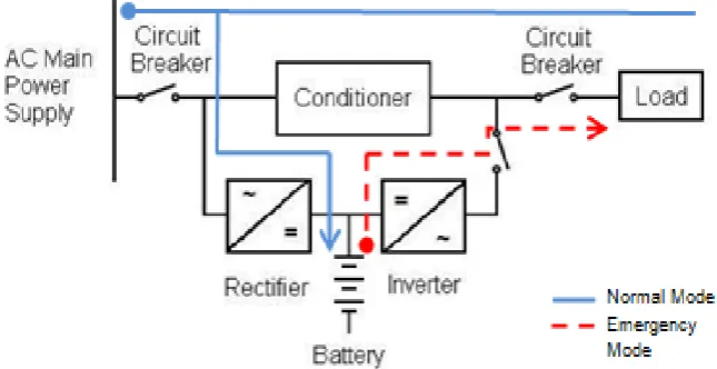
2.3.1 Passive Standby UPS
Passive Stand-by configuration is illustrated in Figure 2.6. The inverter and battery are connected in parallel with main power supply, and acts as a backup power supply throughout emergency mode. There are two operating modes for Passive Stand-by UPS which are normal and emergency mode.
outside of range, the battery and the inverter ensuring the continuity in the supply of power to a load by performing a switching manually. Throughout the emergency mode, the load continues received a power supply from the battery for the duration of back up time or until the AC main power supply returns to within the range. Then, UPS operated in normal mode.
[image:17.595.152.475.334.500.2]Advantages of the Passive Standby UPS are simple design, low cost and small in size. The disadvantages include the lack of real isolation of the load from the upstream distribution system, no regulation of output voltage, no regulation of the output frequency and long switching times [1]. Generally, the performance is acceptable for some application but not for large and complex groups of sensitive loads. Other name for above topologies is off-line UPS.
Figure 2.6 Block diagram of Passive Stand-by UPS
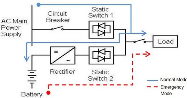
2.3.2 Line Interactive UPS
In normal mode, the load is supplied with conditional power [11]. The inverter operates to provide output voltage conditioning and at the same time charging the battery, with the output frequency dependent. When AC main power supply goes outside of specified tolerance, the inverter and battery maintain the continuity of power supply to the load within specific time frame throughout the emergency mode. The static switch 1 disconnects the AC power supply to prevent back feed from the inverter. The UPS runs on the emergency modes. Lack of effective isolation, poor protection and no regulation of output frequency are main disadvantages of this topology. However, lower costs than a double conversion UPS at equal power rating is main advantages of this topology.
Figure 2.7 Block diagram of Line Interactive UPS
2.3.3 Double Conversion UPS
For double conversion UPS as illustrated in Figure 2.8, the inverter is connected in series between the AC main power supply input and the load. Load will receive a quality power continuously through inverter. Three operating modes are defined by standards: normal, emergency and bypass mode.
in float mode as a backup. At the point of electric power or AC input supply voltage are outside of UPS present tolerance, inverter and battery will continuous support the load. At this point, UPS running on the emergency mode for estimated back up time. When AC input supply return to acceptable range, load will supplied thro rectifier/charger-inverter or back to normal mode.
Figure 2.8 Block diagram of double conversion UPS
Advantages of double conversion UPS is having a bypass line. In bypass line, the main component is static switch. Function of static switch is to ensure instantaneous transfer of power input supply from inverter output to the bypass AC input. In the event of internal fault or battery back-up time run out, load will be transfer to the bypass AC input without interruption. High price is the only disadvantage of the above system.
2.3.4 Double Conversion UPS with Redundancy
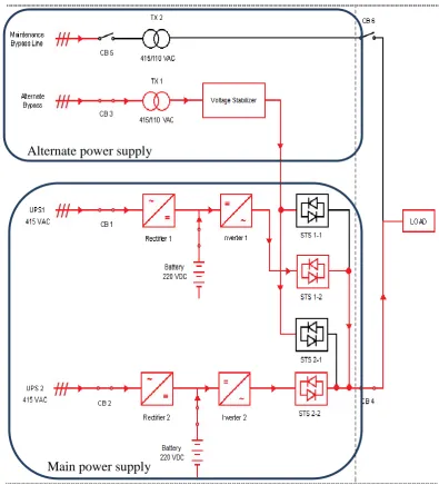
In this study, block diagram of existing UPS was shown in Figure 2.9. The UPS system was classified as double conversion UPS with redundancy. The configuration not only allows a significant increase of the system’s reliability, availability but also improves the total power capability in regard to overload and short circuit. There are four input of power supply namely UPS 1, UPS 2, alternate bypass and maintenance bypass. All units are put in parallel mode.
During normal operation in UPS 1 and UPS 2, rectifier coverts the AC power to DC power and the output of the rectifier is continuously supply power to the loads via inverter and closed static switch. At the same time, battery will be charged by rectifier output. Battery act as energy storage tank, which is continuously kept in a fully charged condition by the rectifier output as long as AC power is available. Both UPS 1 and UPS 2 were in synchronous mode. Thus it’s have a same priority and each UPS equally sharing the total load, 50% each.
Meanwhile alternate bypass line was in stand-by mode, connected to the load with open static switch. In the event of deviation in the inverter output voltage or frequency which outside the permissible tolerance due to fault, the static switch shall initiate uninterrupted transfer of the load form UPS 1 or UPS 2 to the alternate bypass supply. Loads were transferred immediately by the action of solid state transfer switch. In case of rectifier failure, battery will take over by supplying the power to the load. Therefore, continuity of power flow to the load is very high.
Figure 2.9 Block diagram of Double Conversion UPS with redundancy
The main attractiveness of redundancy UPS are availability and reliability. However the requirements to achieve flexibility so that it can meet to all various demanding applications are stated below:-
1. Parallel inverter shall have separate system on the critical control. It’s means that all inverters must be independent to each other. This will ensure the operation are truly redundant in operation
2. Load sharing between inverter should achieve with minimum scale of communication.
3. The system should be modular and easily expendable [13]. Main power supply
2.4 Transfer Switches
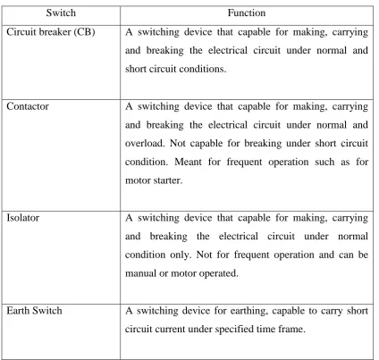
[image:22.595.106.531.314.717.2]According to National Electric Manufacture Association (NEMA) standard SG-50-620, switch is a device for making, breaking or changing the connection in the electrical circuit. Different type of switches have a different function, however main function of switches used in the electric distribution system are for opening and closing of an electric circuit [14]. Switches are also providing protection to the equipment and it can be operated manually, automatic or a combination of automatic and manual. The brief function for common switches was shown in Table 2.1
Table 2.1 Function of common switches
Switch Function
Circuit breaker (CB) A switching device that capable for making, carrying and breaking the electrical circuit under normal and short circuit conditions.
Contactor A switching device that capable for making, carrying and breaking the electrical circuit under normal and overload. Not capable for breaking under short circuit condition. Meant for frequent operation such as for motor starter.
Isolator A switching device that capable for making, carrying and breaking the electrical circuit under normal condition only. Not for frequent operation and can be manual or motor operated.
2.4.1 Automatic Transfer Switch (ATS)
Automatic transfer switch (ATS) is wide spread technologies used for switchover the essential loads from preferred to standby power supply. ATS are operated using relay logic or programmable logic controller (PLC) to monitor the status of preferred source for fault condition. Upon recognizing a particular fault within the preferred source, the relay or PLC was configured to switch in the standby source. Normally, it takes about 2 to 10 cycles or 40ms to 200ms for the transfer. There are two types of transfer scheme namely break before made and make before break.
For break before made, it was designed in the way the power to the load will be cut off before load was shifted to standby power. The advantage of the scheme is the main power supply and standby power can never in parallel mode during the changeover. Expected the current will go to zero amps before standby power ON and feed the load. Marginally the required transfer time is exceeding the power quality guideline for maintaining the essential load. This may result in a plant shutdown.
In make before break, expected the power is continuously feed to the load. The downside of the system is the main and bypass power supply must be in synchronous mode which the electrical parameter such as voltage amplitude, phases, frequency and phase angle must be matching.
However, for the UPS system, two inverter units must comply to below requirements before implementation of make before brake:-
1. Synchronization with other inverters or grid 2. Equal sharing of active and reactive power 3. Minimization of circulating currents 4. Overload protection
5. Strict voltage tracking
6. Frequency of operation has to be maintained [15]
2.4.2 Solid Static Transfer Switch (SSTS)
Power electronic switches such as thyristor were introduced in 1960’s by General Electric Company. It is to overcome the inherent constraints of ATS operation such as slow speed, bulky component and frequent contact failure. Power electronic switch were also designed to meet the demand for fast load transfer and meet the ride through capability requirement for critical loads.
A universal switch that enables the transfer of electrical loads from AC main power source to another in less than half of cycle is solid state transfer switch (SSTS). SSTS had been long used in UPS to switch sensitive loads from main power to alternate power supply as fast as possible, regardless of the load type and the disturbance. It has excellent properties as no moving part, small, robust, microsecond switching times, low power consumption and potentially cheap. The most significant advantage over ATS is that the electrical sources are never cross connected unintentionally by using SSTS. In another word, SSTS can be used very effectively to ensure continuity of power supply to the sensitive loads and at the same time protect the load against voltage sag, swell and other electrical disturbance.
SSTS Structure and Operation
The SSTS system as shown in Figure 2.3 consists of
1. Switches block, S1 and S2, where two unit thyristors connected back to back in each switches block and located between power supplies and load
2. Two power supplies, one supply is main power supply and other supply is bypass power supply
3. A load, RL load which is sensitive to the discrepancy of voltage supply or regenerative load such as motor and etc.
Control system consist of control logic which governor the operation of the two block switches. The duration of operation of the switches to transfer the load and results from the operation will define the performance of the overall system especially SSTS. In other word, performance of SSTS is determined by total load transfer time and zero current crossing phenomena. Total load transfer time (T_tot) is sum of detection time in voltage detection logic (T_det) and transfer time in load transfer mechanism (T_tran) [16].
The sequences of transfer start with the voltage detection system which responsible to monitor the quality of source voltages and issue the transfer command to control system when the main power supply cannot meet the load requirement. The system monitors maximum and minimum value of voltage waveform at the load every half of cycle and check whether the supply voltage within the prescribe range. If disturbance detected, voltage detection system initiate the transfer by sending error input to the gating strategy. Errors may happen which will give an impact to T_det due to insufficient precision of voltage measurement and smoothing filtering. A result from insufficient precision measurement system to the voltage detection system is wrong voltage direction. Error of smoothing filter will give an impact to the zero crossing and subsequently impact the T_det.
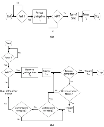
For T_tran, it is depends on the gating strategy. Two common schemes for gating strategy namely zero-current and commutation gating strategy can be applied. Gating strategy provide a suitable gating pattern for the thyristor switch before, during and after a load transfer based on the direction of line current. Both process flows of gating strategies were shown in Figure 2.10. In the commutation strategy, the control system does not wait for the current zero crossing; transfer will start as soon as possible when the disturbance occurs. However, to ensure no paralleling between the two sources, the transfer proceed when the direction of line current are at zero crossing. Meanwhile, in zero-current strategy, the initiation of transfer will start once zero crossing is reached which lead long transfer time. Therefore commutation gating strategy can be employed to achieve a faster load transfer compare to the zero-current gating strategy [17]. The total load transfer time (T_tot) are effected by
2. Disturbance characteristic which determines voltage difference between the main supply and alternate supply and the voltage drop across the incoming and outgoing thyristor switches during load transfer.
3. Load type which control the voltage phase difference and line current zero crossing.
(a)
[image:26.595.119.524.196.692.2](b)
In summary, when the disturbance occurs, expected transfer scenario of the SSTS system as per below:-
1. Successful commutation takes place between main thyristor and alternate thyristor. Then the transfer time is only commutation time.
2. Commutation between the thyristor starts but polarity of the commutation voltage changes. Then the transfer processes are hold until next zero crossing. In this case the transfer time is commutation time plus time to next zero crossing which highly depended to the characteristic of load.
3. Commutation does not occurs and the transfer process is started until next zero crossing. Now the transfer time depends on the voltage phase difference and load characteristic.
SSTS Performance for Phase Difference
Conventionally, SSTS in the parallel UPS system are always connected in the condition of voltage sources in phases and phase’s difference is negligible. In some situation as below, SSTS are connecting the sources in around ten degree phase variance:-
1. When main power supply coming from utility system and alternate power is feed from local generation, this will create difference phase angle as different power sources.
2. In the case of same power supply, different in feeder impedance due to transformer and upstream load also lead to the phase angle different.
the successful commutation results in a negligible transfer time [18]. On the other hand, if the main supply lagging the alternate source, the probability of commutation failure increase due to negatively biased thyristors.
[image:28.595.131.499.287.443.2]Further simulation was conducted on two types of load which RL Load and regenerative load. In this simulation, main power supply is subjected to the voltage sag from 15% to 100%. A phase difference is varied from 0 to 25 degree and main power supply in state of leading the alternate power supply. The corresponding time on the disturbance detection time and transfer time are calculated and compared. The results for RL load are summarized in Figure 2.12.
Figure 2.11 Block diagram of STS-1 benchmark system [19].
[image:28.595.125.513.500.742.2]The reflections from above figure are
1. The effect of phase angle difference on the SSTS is negligible except for the severe voltage disturbance.
2. Even at zero phases different, the total transfer time at the 25% and 41% voltage sag is higher compare to the rest. When the main power supply is lead 1.25 degree, the commutation failures disappear. In this case, the commutation voltage is not high enough to complete the load transfer before the commutation voltage polarity changes.
3. For voltage sag of 25%, it is requires about 6deg phase shift to make successful commutation and final transfer the load from main power to alternate supply.
[image:29.595.123.523.453.712.2]The results for regenerative load are summarized in Figure 2.13. The reflection from the figure is the effect of phase difference is not significant. For voltage sag over 83%, the detection time is short compare to the transfer time, and the process of transfer is accompanied by the regenerative mode regardless of the phase difference.
REFERENCES
[1] S. Karve, “Three of a kind”, IEEE Review, vol. 46, no 2, pp. 27-31, March 2000.
[2] Cosse, R.E. Dunn, D.G.Spiewak, R.M., “Is My UPS Distribution System Coordinated?” IEE Conference Publications, 2006, Page(s): 1 – 18.
[3] M.C. Chandorkar, D.M. Divan, Y. Hu, B. Banerjee, “Novel Architectures and Control for Distributed UPS Systems”, conf. rec., APEC 1994, Orlando, pp. 683-689.
[4] Holtz, J. and Werner, K-H., “Multi-Inverter UPS System with Redundant Load Sharing Control”, IEEE Trans. on Ind. Electronics, Dec. 1990, pp. 506-513.
[5] Al-Qahtani, A.M., Lourido, M.L., Dabbousi, R.M.O., Al-Shahrani, O.O, “Management of Electrical Equipment Obsolescence at Oil & Gas Industrial Facilities” IEE Conference Publications, 2010, Page(s): 1 – 8.
[6] Hitt, F. and Schmidt, J., “Technology Obsolescence (To) Impact on future Cost”, IEE Conference Publications, 1998.
[7] Yoshida, T., Hirose, K., Hashiwaki, M., Yamamoto, T., Serada, T. and Kawawaki, T. “Portable Transfer Switch for interruption free UPS replacement” IEEE, 2003.
[9] Tuladhar, A., Jin, H., Unger, T. and Muach, K. “Parallel Operation of single Phase Inverter Modules with No Control Interconnection” IEEE-APEC’98, Vol. 1, pp. 235-238, 1997.
[10] Bekiarov, B.S. and Emadi, A., “Uninterruptible Power Supplies: Classification, Operation, Dynamics and Control”, in proc. IEEE-APEC’02 Conf., 2002, pp. 597-604.
[11] Krishnan, R. and Srinivasan, S., “Topologies for Uninterruptible Power Supplies”, IEEE, 1993.
[12] Yaskiv, V. and Hirnyak, R., “The comparative Analysis of UPS Topology”, IEEE, 2004.
[13] Byun, Y.H., Koo, T.G., Joe, K.Y., Kim, E.S., Seo, J.I., and Kim, D.H., “Parallel Operation of Three Phase UPS Inverters by wireless Load Sharing Control”, IEEE, 2000.
[14] Acha, E., Agelidis, V.G, Anaya-Lara, O. and Miller, T.J.E., “Power Electronic Control in Electrical Systems”, Newnes Power Engineering Series, ISBN 0 7506 5126 1, 2002.
[15] Sahoo, L.K., Thakur, N.D., Rai, K., Sensarma, P., Jha, R.D., Mohanty, P. and Sharma, A., “Synchronization and Operation of Parallel Inverters Using Droop Control
[16] Mokhtari, H., Dewan, S.B. and Iravani, M.R., “Analysis of a static transfer switch with respect to transfer time,”IEEE Trans. Power Del., vol. 15, no. 1, pp. 190– 199, Jan. 2002.
[18] Mokhtari, H. and Iravani, M.R., “Effect of Source Phase Difference on Static Transfer Switch Performance”, IEEE, 2007.
[19] Mokhtari, H. and Iravani, M.R., “Impact of Difference of Feeder Impedance on the Performance of a Static Transfer Switch”, IEEE 2004.
[20] Seymour, J., “ The seven Type of Power Problems”, White paper 18, 2001
[21] Information Technology Industry Council: http//www.itic.org.
![Figure 2.3 Schematic diagrams for SSTS [8]](https://thumb-us.123doks.com/thumbv2/123dok_us/8774827.900821/14.595.123.521.70.291/figure-schematic-diagrams-for-ssts.webp)
![Figure 2.4 Voltage of waveform at the load when SSTS is in operation [8]](https://thumb-us.123doks.com/thumbv2/123dok_us/8774827.900821/15.595.124.511.77.266/figure-voltage-waveform-load-ssts-operation.webp)