http://dx.doi.org/10.4236/msa.2015.64037
How to cite this paper: Murase, H., Kawasaki, S., Kitaoka, T., Furukawa, J., Ueda, H., Nishimura, H. and Yamada, K. (2015) Effects of Polysilane-Coating on Interface of Electrofusion Joints for Maintaining Strength. Materials Sciences and Applica-tions, 6, 322-331. http://dx.doi.org/10.4236/msa.2015.64037
Effects of Polysilane-Coating on
Interface of Electrofusion Joints for
Maintaining Strength
Hiroaki Murase
1, Shinichi Kawasaki
1, Toshimichi Kitaoka
1, Jouji Furukawa
1,
Hirofumi Ueda
1, Hiroyuki Nishimura
2, Kazushi Yamada
2* 1Osaka Gas Co., Ltd., Osaka, Japan2Advanced Fibro-Science, Kyoto Institute of Technology, Kyoto, Japan
Email: *[email protected]
Received 4 March 2015; accepted 10 April 2015; published 14 April 2015
Copyright © 2015 by authors and Scientific Research Publishing Inc.
This work is licensed under the Creative Commons Attribution International License (CC BY). http://creativecommons.org/licenses/by/4.0/
Abstract
The fusion strength of electrofusion joints using the polyethylene (PE) pipe connection greatly depends on the amount of sand which adheres to the interface by wind and so on, because there is no flow of melted resin at the fusion interface on electrofusion joints. Therefore, it is necessary to develop a method to prevent the fusion strength from reducing even in the case of sand adhesion. In this study, the fusion interface coated with polysilane, a kind of silicon polymer, effectively prevented the reduction of the fusion strength even if contaminated by sand. It was found that it brought the improvement of the fusion strength since when there was polysilane on the fusion in-terface. PS deeply permeated the polyethylene layer and lowered the viscosity of polyethylene.
Keywords
Polysilane, Electrofusion Joint
1. Introduction
Since the Gas Utility Industry Law was revised to permit the use of PE pipes in 1982 in Japan, the PE pipes are steadily spreading as gas feed pipes. After the Hanshin-Awaji Great Earthquake Disaster in 1995, flexibility of the PE pipe and reliability of the joint systems have been highly evaluated and the pipe and joint systems are being rapidly introduced. Therefore, the PE pipes and joint systems play an important role in gas supply. It is an inevitable mission for the gas supply business to perform technical innovation for improving reliability of the PE
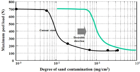
However, the pipe surface may suffer from dirt such as fine sand particles due to wind blowing at the work sites irrespective of pre-treatment as described above. The fusion strength of electrofusion joints depends on the amount of sand particles adhered to the interface (Figure 2) because flow rate of molten resins is poor at the fu-sion interface on electrofufu-sion joints. Although simple methods, for example, “non-destructive inspection tests”, for inspecting the condition of an electrofusion joint have been developed, they are often ineffective when par-ticles adhere on the interface. Therefore, it is necessary to develop a method to prevent the fusion strength from reduction even when sand particles adhere on the joint interface [1]-[4].
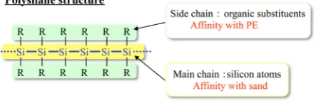
Polysilane has recently attracted considerable attention due to their usefulness as the precursors for thermally stable ceramics [5] [6], a material for microlithography [7]-[9], and also due to their potentiality [10] [11] in the preparation of new types of material showing semiconducting [12] [13], photo-conducting [14] [15], or nonli-near optical [16]-[18] property. Polysilane is a kind of silicon polymers composed of only silicon atoms (Si-Si bonds) as the main chain and having organic substituents such as methyl and phenyl groups. As may be conjec-tured from the chemical structure formula, polysilane has an affinity to sand particles (SiO2) owing to the
[image:2.595.153.447.350.514.2]pres-ence of silicon as constituents of the main chain, as well as an affinity to polyethylene because Polysilane is a non-polar substance similar to polyethylene (Figure 3) [19].
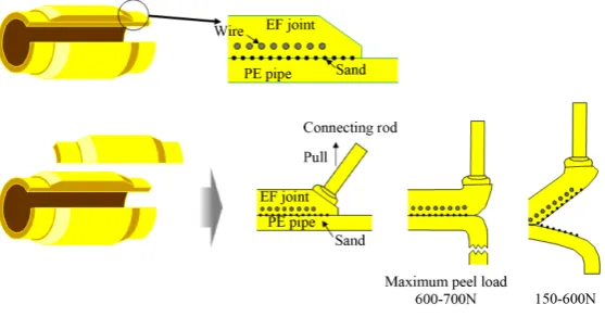
Figure 1. Schematic illustration of work procedure of electrofusion joints.
Figure 2. Relation between degree of sand contamination and maximum peel
[image:2.595.155.442.542.690.2]Figure 3. Schematic illustration of polisilane structure and its feature.
From the view point as described above, it is considered that decrease of fusion strength may be suppressed in the presence of polysilane at the fusion interface of electrofusion joints, even when sand particles are adhered on the joint. It has been found in our study that a kind of polysilane was very effective for maintaining the fusion strength at electrofusion joints when sand particles were adhered on the fusion interface. Some analyses were conducted from the chemical and physical point of views and it was observed that polysilane molecule per-meated into the PE resin deeply and hence the PE resins of the PE pipe and electrofusion joint were thought to be thoroughly mixed with each other.
2. Experimental
2.1. Preparation of Polysilane
Polysilane (1) was prepared by reductive coupling of monomers (dichlorosilanes) using metallic magnesium in the presence of specified catalysts and solvents [20]-[22]. Into a 100 ml round bottomed flask were added THF (30 ml, dried over Na), Mg powder (40 mmol), LiCl (20 mmol), and ZnCl2 (4 mmol) as a Lewis acid under N2
atmosphere and stirred to solve LiCl and ZnCl2 to THF for an hour. Dichlorosilane (30 mmol) was added into
the flask, and the mixture was stirred for 24 h at room temperature. After 3 ml of water and toluene (50 ml) was added into the reaction mixture, it was filtered to remove Mg salts. The filtrate was poured into an ice cold solu-tion of HCl (1 M/dm3, 100 ml) and the aqueous solution was extracted with toluene (50 ml × 3). The combined organic layers were washed twice with 50 ml of brine, dried over MgSO4, and concentrated (Scheme 1).
Three-types of polysilane were prepared using above mentioned method (Table 1). 1a and 1b have a linear structure and 1a has much higher molecular weight than that of 1b which is blocked up by trimethylsilyl (TMS) groups. On the other hand, 1c has a cyclic structure (Figure 4).
2.2. Coating Method of Polysilane
A solution of polysilane was added into a PE cleaner soaked in a sheet of wiping paper for use in on-site clean-ing of pipes and electrofusion joints. After scrapclean-ing, a PE pipe with a diameter of 50 mm and an electrofusion joint whose surface was cleaned with the PE cleaner were coated with polysilane. The PE pipe with a diameter of 50 mm was coated with about 4 mg of polysilane by wiping with a polysilane solution with a concentration of about 3 wt%. Finally, sand particles having a diameter of less than 100 μm were scattered on the coating portion of the pipe (Figure 5).
2.3. Evaluation of Fusion Strength of Electrofusion Joints (Peel Test)
As shown in Figure 6, test samples with a width of 1 cm was cut from the joint portion of the PE pipe and elec-trofusion joint in a direction parallel to the PE pipe. Eight sample pieces were obtained from the PE pipe having a diameter of 50 mm. The test piece was fixed to a tensile machine to determine the maximum peeling load ap-plied at the fusion interface between the PE pipe and electrofusion joint. By elongating the PE pipe, the maxi-mum peeling load was increased up to 700 N, and showed a rapid decrease by peeling at the fusion interface. The weld energy was calculated from the peel load at each elongation distance.
3. Results and Discussions
3.1. Verification of the Effect of Polysilane Coating
3.1.1. Effect of Structure of Polysilane
Scheme 1. Synthetic method of polisilane using Mg, LiCl and Lewis acids.
Si Ph
OH HO
Me n
Si Ph
TMS TMS
Me n
Si Ph
Ph n
[image:4.595.159.436.81.148.2]1a 1b 1c
[image:4.595.175.431.276.411.2]Figure 4. Detailed chemical structures of polisilane.
Figure 5. Schematic illustration of coating method of polisilane.
Figure 6. Schematic illustration of peel test and evaluation method thereof.
that decrease of the maximum peel load was greatly suppressed, or decrease of the fusion strength was sup-pressed by coating 1b as compared with the maximum peel load obtained without coating any polysilane. No suppressing effect was observed by coating 1a. 1c exhibited no effects. Accordingly, it was revealed that poly-methylphenylsilane (1b) having low molecular weight is the most suitable as the molecular structure for en-hancing the peeling strength.
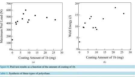
3.1.2. The Relation between the Amount of Coating of 1b and Peeling Strength
[image:4.595.159.438.440.586.2]Figure 7.Results of peel test on three types of polisilane.
[image:5.595.90.539.312.568.2]
(a) (b)
Figure 8. Peel test results as a function of the amount of coating of 1b.
Table 1. Synthesis of three-types of polysilane.
Run Monomer structure Polysilane structure Mwa
1 MePhSiCl2 HO-(MePhSi)n-OH (1a) 10,000 (n = 80)
2 MePhSiCl2 + Me3SiCl TMS-(MePhSi)-TMSb (1b) 1000 (n = 7)
3 Ph2SiCl2 (Ph2Si)n (1c) 1000 (n = 5)
a
Determined by GPC based on polystyrene standard. bTMS shows trimethylsilyl group.
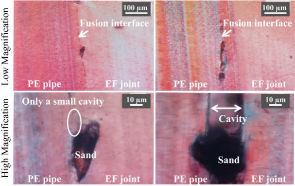
[image:5.595.87.544.565.637.2]the micro-interaction mode between the polysilane molecule and PE layer by Electron probe micro analyzer (EPMA). The states of the fusion interface of the following samples were observed under a polarized light mi-croscope (Figure 9). Many cavities with a dimension of about 100 μm were observed in the vicinity of sand
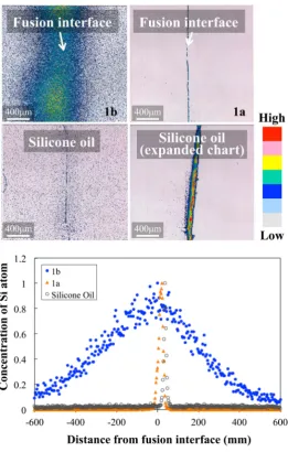
par-ticles adhered on the fusion interface. When 1b that had exhibited an effect in the peel test was coated, the cavi-ties were almost disappeared, showing that the sand particles were favorably adhered to PE. The concentration of Si atoms contained in the vicinity of the fusion interface was determined using EMPA. The results are shown in Figure 10. In case of 1a with high molecular weight polysilane and silicone oil as a representative silicon po-lymer that had exhibited no effect in the peel test, Si atoms still remained in the vicinity of the fusion interface. On the other hand, only 1b was permeated into the PE layer from the fusion interface at a width of as many as 1 mm in maximum. It can be concluded from the results above that, although PE having a melting point at around 126˚C is in a melt state since the temperature at the fusion interface reaches about 210˚C, the PE resin is not thoroughly mixed at the portion adhered with the sand particles. When 1b is coated, on the other hand, 1b mo-lecules so deeply permeate into the PE resin, that is, the PE resins of the PE pipe and electrofusion joint are thought to be thoroughly mixed with each other.
3.2.2. Analysis of Mixing State of PE and Polysilane
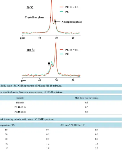
In order to analyze how physical properties of the PE-1b mixture differs from those of the PE alone at a temper-ature higher than the melting point, compatibility of PE with 1b was assessed by melting point measurement us-ing Differential scannus-ing calorimetry (DSC), melt flow rate measurement and 13C solid state NMR. The result of the melting point measurement of the PE-1b mixture by DSC is shown in Figure 11. The result indicated that the melting point decreased about 2˚C by mixing 1b with PE. The result of melt flow rate measurement showed that the rate increased by about two times by mixing 33 wt% of 1b with PE, showing that viscosity of PE at the melting point decreased by mixing 1b (Table 2). Mixing of 1b with the PE resin was promoted as a result of in-creased melt flow rate in the vicinity of the fusion interface. The solid state 13C NMR spectrum of the PE-1b
mixture at 70˚C and 110˚C is shown in Figure 12, and peak intensity ratios at each temperature are shown in
Table 3.
[image:6.595.147.451.512.703.2]While the ratio between the crystalline phase peak and amorphous phase peak of PE did not change at a tem-perature of 70˚C or less by mixing 1b, the ratio of the amorphous phase peak increased at a temperature of 90˚C
Figure 10. Concentration of Si atoms in the vicinity of the fusion interface
as determined by EPMA.
[image:7.595.161.436.525.708.2]Figure 12. Solid state 13C NMR spectrum of PE and PE-1b mixture.
Table 2. The result of melts flow rate measurement of PE-1b mixture.
Sample Melt flow rate (g/10min)
PE resin 0.3
PE:1b (3:1) 0.5
[image:8.595.95.536.499.625.2]PE:1b (1:1) 0.8
Table 3. Peak intensity ratio in solid state 13C NMR spectrum.
Temperature (˚C) A/C ratioa PE PE-1b (1:1)
50 0.4 0.4
70 0.5 0.5
90 0.7 0.8
100 1.2 1.3
110 1.8 2.2
115 2.6 2.8
120 3.1 3.7
a
A/C ratio shows the ratio of amorphous phase to crystalline phase.
or more. According to Cross polarization/Magic angle spinning (CP/MAS) used in the solid state 13C NMR measurement, the signal intensity of the crystalline phase is suppressed as molecular motion becomes active [23] [24]. Accordingly, it was shown from the results above that molecular motion of PE molecules was activated by dissociating the crystalline phase at a temperature of 90˚C or more. This means that 1b is a material excellent in affinity with PE in molecular levels.
was adhered was suppressed by coating 1b on the fusion interface by the following reasons. It can be conjec-tured from the results of the melting point measurement by DSC and melt flow measurement that viscosity of the PE resin is decreased by the presence of 1b in the PE resin to enhance fluidity of the resin, thereby promot-ing mixpromot-ing of the PE resins. The fact that 1b is a material having excellent affinity with the PE resin is an im-portant factor for promoting mixing of the PE resins (see the sections of EPMA and solid state 13C NMR).
4. Conclusion
It had been examined the effects of polysilane for maintaining the fusion strength at electrofusion joints when sand particles were adhered on the fusion interface. A kind of polysilane which had methyl and phenyl group with low molecular weight was very effective to enhanced fusion strength. The reasons were also examined from the chemical and physical point of views. Polysilane molecule permeated into the PE resin deeply and hence the PE resins of the PE pipe and EF joint were thought to be thoroughly mixed with each other.
Acknowledgements
Work of preparation of polysilane was supported by Kindai University in Japan. The authors gratefully ac-knowledge to Professor Shigenori Kashimura, Faculty of Engineering, Kindai University, in Japan.
References
[1] Nishimura, H., Suyama, M., Inoue, F., Higuchi, Y. and Ishikawa, T. (1995) An Evaluation Method for Electrofusion Joint Strength of Polyethylene Pipes for Gas Distribution. Proceedings of Plastics Pipes IX, 162-167.
[2] Marshall, G.P., Hepburn, D.S. and Netherwood, N. (1995) Improvements in Electrofusion Welding in the US Water Industry. Proceedings of Plastics Pipes IX, 153-161.
[3] Nishimura, H., Suyama, M., Inoue, F. and Ishikawa, T. (1995) Design and Evaluation Methods for Electrofusion Joints of Polyethylene Pipes for Gas Distribution. Proceedings of ANTEC 1995, 1212-1216.
[4] Tubakimoto, T., Nishimura, H., Ishikawa, T. and Ueda, H. (1997) Trend in Technological Development of Polyethy-lene Pipes. International Plastic Pipe Symposium, 177-184.
[5] Yajima, S., Hayashi, J. and Omori, M. (1975) Continuous Silicon Carbide Fiber of High Tensile Strength. Chemistry Letters, 4, 931-934. http://dx.doi.org/10.1246/cl.1975.931
[6] Hasegawa, Y. and Okamura, K. (1986) Synthesis of Continuous Silicon Carbide Fibre. Part 4. The Structure of Poly-carbosilane as the Precursor. Journal of Materials Science, 21, 321-328. http://dx.doi.org/10.1007/BF01144739
[7] Srinivasan, R. (1986) Ablation of Polymers and Biological Tissue by Ultraviolet Lasers. Science, 234, 559-565.
http://dx.doi.org/10.1126/science.3764428
[8] Miller, R.D., Willson, C.G., Wallraff, G.M., Clecak, N., Sooriyakumaran, R., Michl, J., Karatsu, T., McKinley, A.J., Klingensmith, K.A. and Downing, J. (1989) Polysilanes: Photochemistry and Deep UV Lithography. Polymer Engi-neering Science, 29, 882-886. http://dx.doi.org/10.1002/pen.760291311
[9] Miller, R.D., Wallraff, G.M., Clecak, N., Sooriyakumaran, R., Michl, J., Karatsu, T., McKinley, A.J., Klingensmith, K.A. and Downing, J. (1989) Polysilanes: Solution Photochemistry and Deep UV Lithography. Polymer Materials Science Engineering, 60, 49. http://dx.doi.org/10.1021/bk-1989-0412.ch008
[10] Miller, R.D. and Michl, J. (1989) Polysilane High Polymers. Chemical Reviews, 89, 1359-1410.
http://dx.doi.org/10.1021/cr00096a006
[11] Miller, R.D. (1989) Polysilanes—A New Look at Some Old Materials. Angewandte Chemie International Edition in English, 28, 1733-1740. http://dx.doi.org/10.1002/anie.198917331
[12] West, R., David, L.D., Djurovich, P.I., Stearley, K.L., Srinivasan, K.S.V. and Yu, H. (1981) Phenylmethylpolysilanes: Formable Silane Copolymers with Potential Semiconducting Properties. Journal of the American Chemical Society,
103, 7352-7354. http://dx.doi.org/10.1021/ja00414a061
[13] Naarman, H., Theophilou, N., Geral, L., Sledz, J. and Schien, F. (1988) Electrically Conductive Polysilanes. German Patent DE3634281.
[14] Kepler, R.G., Zeigler, J.M., Harrah, L.A. and Kurtz, S.R. (1987) Photocarrier Generation and Transport in σ-Bonded Polysilanes. Physical Review B, 35, 2818-2822. http://dx.doi.org/10.1103/PhysRevB.35.2818
[15] Fujino, M. (1987) Photoconductivity in Organopolysilanes. Chemical Physics Letters, 136, 451-453.
http://dx.doi.org/10.1016/0009-2614(87)80285-3
Poly-[19] Murase, H., Sakamoto, H. and Fujiki, T. (2008) Manufacturing Method of Polysilane Copolymers. Patent JP 4205354.
[20] Murase, H., Fujiki, T. and Sakamoto, H. (2000) Synthesis of Polysilanes and Related Polymers Using Magnesium and Metal Chloride Catalysts. RadTech Japan Symposium, 110.
[21] Murase, H., Sakamoto, H. and Fujiki, T. (2010) Manufacturing Method of Polysilane Using Activated Magnesium. Patent JP 4559642.
[22] Kashimura, S.,Tane, Y., Ishifune, M., Murai, Y., Hashimoto, S., Murase, H., et al. (2008) Practical Method for the Synthesis of Polysilanes Using Mg and Lewis Acid System. Tetrahedron Letters, 49, 269-271.
http://dx.doi.org/10.1016/j.tetlet.2007.11.088
[23] Schaefer, J., Stejekal, E.O. and Buchdahl, R. (1977) Magic-Angle 13C NMR Analysis of Motion in Solid Glassy Poly-mers. Macromolecules, 10, 384-405. http://dx.doi.org/10.1021/ma60056a031