© 2018, IRJET | Impact Factor value: 6.171 | ISO 9001:2008 Certified Journal | Page 1427
Design, Analysis and Simulation of Double Wishbone Suspension
System for Formula Student Vehicle
Aditya Sinha
1, Ashish Jagtap
2, Saumitra Deshpande
31,2,3
Student, Mechanical Engineering, RMD Sinhgad School of Engineering, Maharashtra, India
---***---Abstract -
The main aim of the paper is to design andanalyze the suspension system for a formula student vehicle. The suspension system is one of the main systems to be considered while designing any formula student vehicle. The aim of the paper is also to lay a proper methodology for designing and analysis of a suspension system which includes knuckle, wishbones and spring. ADAMS is used for the dynamic simulation of the system. Special emphasis is laid on achieving accurate results by using software based analysis. The results of the simulation in ADAMS are also shown for better understanding of the system. The 3D modeling of the system is done in CATIA V5R21. Analysis is carried out in ANSYS V16. Dynamic simulation is carried out in ADAMS.
Key Words: Suspension, Double wishbone, spring,
ADAMS, ANSYS
1. INTRODUCTION
When people think of vehicle performance, they normally think ofmore HPs, NMs and zero-to-100 acceleration. But all of the power generated by an engineis useless if control is lost. That's why automobile engineers concentrated on suspension system as soon as they mastered power generation. The suspension system serves the function of providing assistance to the steering system in the front and power transmission systems in the rear for rear wheel drive vehicles. If a road was flat, with no bumps and droops, suspensions would be unnecessary. But roads are far from flat. Even the most maintained highways have defects that can disturb with the wheels of a car. It's these defects that apply forces to the wheels. A bump in the road causes the wheel to move up and down perpendicular to the stub axle. The magnitude, of course, depends on whether the wheel is striking a giant bump or even gravels. Without a negotiating structure, all of wheel's vertical energy is transmitted to the chassis, which moves in the same direction. In such a situation, the interaction with the road is lost completely. Then, under the downward force of gravity, the wheels can hit back into the surface of the road. The main requirement here is a structure that will absorb the energy and transfer it to the frame without disturbing the whole system. The study of the forces at work acting on a moving car is called vehicle dynamics, and the concepts required for designing suspension system are mentioned below. While designing the suspension system following parameters are considered. Ride - a car's capacity to ease out a bump or droop
Handling - a car's capacity to safely negotiate acceleration, braking and cornering.
2. DESIGN
Designing of whole system is done in two parts:
Basic design of the suspension components and after that testing of designed components. Following steps were followed while designing the system
Part A: Basic design
1. Decide parameters- wheelbase, track width, tyre, wheels and other parameters.
2. Design wishbones and knuckles. 3. Design springs.
Part B: Testing of the designed components
1. Using ADAMS and ANSYS software to check the simulation feasibility and of system.
2. Testing of vehicle by actual run after assembling the system on vehicle.
I.
Basic parameters
The first step of designing is to decide the various basic parameters of the system. The parameters are:
1. Track width = 1320.8mm (52 inch).
2. Wheel base =1574.8 (62 inch). 3. Camber Angle = -10
4. Toe angle = 00
5. Kingpin Inclination angle=5.570
5. Sprung weight = 300 kg
6. Weight distribution = 40:60 (front: Rear)
From market survey and cost consideration 12”× 5.5” wheels selected. Ground clearance, knuckle packaging, weight and tyre availability these various factors are considered while selecting wheels.
II.
Design of knuckle and wishbone:
© 2018, IRJET | Impact Factor value: 6.171 | ISO 9001:2008 Certified Journal | Page 1428
A.
Roll Centre Geometry:
Roll Centre is the point about which the vehicle rolls while cornering. The roll centre is the prime point at which the cornering forces in the suspension are reacted to the vehicle body. The location of the roll centre is derived by the suspension geometry, and can be easily found using principles of the instantaneous centre of rotation.
Roll centre is very essential for deciding the wishbone lengths, tie rod length and the geometry of wishbones. It is conventional that all the three elements those are upper wishbone, lower wishbone and tie rod should pursue the same arc of rotation during suspension travel. This means that all the three elements should be displaced about the same centre point called the instantaneous centre of rotation.
Fig -1: Roll centre geometry
Wishbone lengths are obtained by wheel track width and chassis mounting points. The lines of upper and lower wishbones are extended, they intersect at a certain point which is known as Instantaneous center of rotation. Then line is extended from instantaneous center of rotation to a point at which tire is in contact with the ground. The point at which this line intersects the vehicle center line is called the Roll Centre. Now by extending a line from instantaneous center of rotation to the steering arm this gives exact tie rod length.
B.
Knuckle (Upright):
Knuckle is the non-rotating part in the wheel assembly. The stub axle is welded on the knuckle. Any change in the shape of knuckle can lead to the change in the suspension geometry. This will ultimately cause discrepancy in the results. Therefore the knuckle should be durable and practical in manufacturing. Popular metals used for manufacturing knuckles are AL6061 T6, AL7075T6 and to some extent Titanium. These materials are extremely expensive and their machining processes too tend to be on the expensive side. In order to counter these expenses and innovative idea to use a knuckle that has the same strength but uses less expensive materials and machining and yet provides the same strength.
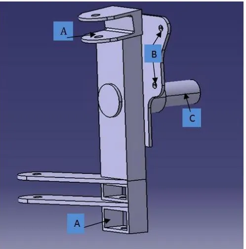
Fig -2: CAD Model of knuckle
Point A represents the mounting points of wishbones to knuckle.
Point B represents mounting point of brake calipers.
Point C represent region for bearing mounting. Bearing press fitted over hub is connected to knuckle in this region.
C.
Analysis of knuckle:
Following forces will act on knuckle –
1) Longitudinal force-Longitudinal load is load to the tyres when the car is subjected to longitudinal acceleration. Longitudinal load acting on knuckle is 538.177N.
2) Lateral force- Cornering or the lateral force is the force produced by a vehicle tyre during cornering. Cornering force is generated by tyre slip and it is proportional to slip angle. Lateral load acting on knuckle is 800N.
3) Wheel Reaction- The wheel exerts an upward normal reaction on the knuckle. This is the total sprung mass distributed as per the mass distribution of the vehicle. The value is found out to be 580N.
[image:2.595.310.559.81.333.2] [image:2.595.36.290.292.438.2]© 2018, IRJET | Impact Factor value: 6.171 | ISO 9001:2008 Certified Journal | Page 1429 Material of knuckle-
Mild steel EN24
Density 7.857 g/cc
Hardness, Rockwell =248 HB
Tensile Strength, Ultimate 850 MPa
Tensile Strength, Yield 680 MPa
Modulus of Elasticity 250 GPa
Poisson's Ratio 0.29
Fig -3: Analysis of knuckle
Result of ANSYS of knuckle:
Max Stress= 198.27N/mm2
Max Deformation = 0.015 mm Factor of Safety = 4.28
D. Analysis of wishbones:
Wishbones are the members connecting the chassis to the wheel assembly. Generally the springs are mounted on the wishbones by using brackets. The wishbones must be properly manufactured for achieving the proper suspension geometry. The provide guide way for the moment of knuckle when experiencing a bump or droop.
Fig -4: CAD Model of wishbone
Following forces will act on wishbones –
1) Wheel Reaction- The wheel exerts an upward normal reaction on the knuckle. This is the total sprung mass distributed as per the mass distribution of the vehicle. The value is found out to be 580N.
2) Spring force- The spring will exert a downwards force on the brackets. This force is calculated to be 1937N. The above force is calculated by considering the dynamic factor found out in experimentation.
[image:3.595.308.559.83.308.2] [image:3.595.41.284.264.481.2] [image:3.595.308.563.481.731.2]© 2018, IRJET | Impact Factor value: 6.171 | ISO 9001:2008 Certified Journal | Page 1430
III.
Design of spring:
Sprung mass = 300 Kg
Mass distribution of 60:40 (Rear: Front)
Mass per wheel at Front = 60 kg
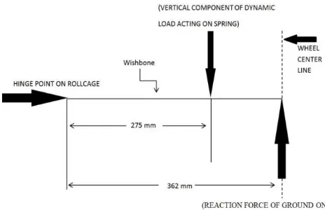
Angle of inclination of the strut = 530
Point of attachment of strut on wishbone from chassis end =10.83” (275mm)
Distance of wheel center from hinge point of roll cage
= 14.25” (362mm)
Reaction force acting from the ground on the wheel = (Mass per wheel * 9.81) N
= (60kg * 9.81) N
= 588.6N
Fig -6: Forces on wishbone
By taking moment about hinge point on roll cage:
588.6 * 362= Spring Force * 275
Spring Force = 774.81 N
Considering the static to dynamic factor=2.5
Dynamic force acting on the spring = spring force*static to dynamic factor
=774.81*2.5
=1937 N
For formula student vehicle, the vehicle should have minimum 2” of spring deflection.
Required Spring Stiffness =Dynamic Spring Force / Spring Deflection = 1937/ 50.8
= 38.13 N /mm
From above calculation we get: Stiffness = 38.13N/mm
Maximum spring force (P) = 1937 N Type of spring: Helical spring
Because of following advantages helical spring is selected
Easy to manufacture & High reliability
Deflection of spring is linearly proportional to the force acting on the spring
Less expensive than others type of springs
Material: Oil hardened steel wire of Grade-2
Ultimate tensile strength = 1100N/mm2
Modulus of rigidity= 77000 N/mm2
According to Indian Standard 4454-1981,
Shear stress=0.5*Ultimate tensile strength
Shear stress ( ) =550N/mm2
Taking spring index (C) =6.33
So,
Wire diameter (d) =8.14≈ 9mm
Mean coil diameter (D)
= C*d
= 6.33*9=57mm
No. of active coils (N):
N=8.69≈9 coils
Assuming that the spring has square and ground ends
Nt = N+2 =11 coils
Solid length of spring = Nt * d
= 99mm
Free length= (Solid length+ +0.15 )
[image:4.595.35.267.339.489.2]© 2018, IRJET | Impact Factor value: 6.171 | ISO 9001:2008 Certified Journal | Page 1431 =14.33mm
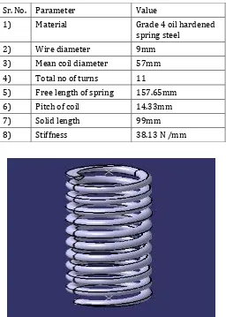
Table -1: Spring values
Sr. No. Parameter Value
1) Material Grade 4 oil hardened spring steel
2) Wire diameter 9mm 3) Mean coil diameter 57mm 4) Total no of turns 11
5) Free length of spring 157.65mm 6) Pitch of coil 14.33mm 7) Solid length 99mm 8) Stiffness 38.13 N /mm
Fig -7: CAD Model of spring
The spring is square end and grounded for better transfer of the forces.
Fig -8: Analysis of spring
Result of ANSYS of spring:
Max Stress= 458.26N/mm2
Max Deformation = 149.79 mm Factor of Safety = 2.4
3. Simulation
The kinematic simulation is carried out on ADAMS software. The simulation shows variations in all the kinematic parameters of the suspension system. All the kinematic parameters affect the dynamic performance of the suspension system. Camber angle generates camber thrust and positive camber thrust for the lateral force and negative camber thrust for the understeer. So, for best ride and handling experience accurate positioning of the joints is needed. The simulation for the above suspension geometry is shown below.
Fig -9: Suspension model in ADAMS
[image:5.595.309.571.302.487.2]Results of the above kinematic simulation are shown below.
[image:5.595.311.557.546.714.2] [image:5.595.38.288.584.746.2]© 2018, IRJET | Impact Factor value: 6.171 | ISO 9001:2008 Certified Journal | Page 1432 Fig -11: Camber angle VS Wheel travel
It is noticeable that the plots begin to deviate when advancing the full bump and full rebound positions. This is due to bump stop and rebound stop generating forces that are then back to the suspension through the bushes. Simulation results are shown in Figure 10-11.Wheel travel is two-way. When wheel travel is positive, camber angle increases. When wheel travel reverses, camber angle decreases with the increasing of the amount of wheel travel.
4. CONCLUSIONS
After designing wishbones, knuckle and spring 3D model built with the help of CATIA and analysis done on ANSYS workbench. Integral assembly were simulated on ADAMS software. Results obtained by simulation match with designed parameters. And after analysing various suspension components, the paper lays down a methodology for analysis of different components. Even for some critical components more than one method are employed to ensure the durability of design. Besides, it is to be noted that “Iteration is the key to perfection”.
REFERENCES
[1] Miliken, William F., Milliken, Douglas L. 1995 “Race Car Vehicle Dynamics”.
[2] Smith, Caroll. 1978, “Tune to win”, Chapter 2, Aero publishers Inc.
[3] Thomas D. Gillespie, “Fundamentals of Vehicle Dynamics”, SAE Inc.
[4] V.B. Bhandari, “Machine Design”, McGraw Hill, 2012.
[5] Abhilash Gunaki, Chinmaya Acharya, etal ‘Design, analysis and simulation of Double wishbone suspension system’, IPASJ International Journal of Mechanical Engineering, Volume 2, Issue 6, June 2014.