http://dx.doi.org/10.4236/jamp.2015.32039
Spectral Imagers with Linear Detector
Imager Systems Based on Spectrum
Compressed
Xiaoming Zhong, Huang Li
Beijing Institute of Space Mechanics & Electricity, Beijing, China Email: [email protected]
Received 14 December 2014
Abstract
Traditional spectral imagers require 2-dimensional detectors. We present a new method to im-plement spectral imagers with linear detector imager systems based on spectrum compressed. Using 1-dimension detectors instead of 2-dimension detectors to get 3-dimensional data cubes, the spectral imagers could get both the spectral information and the spatial information of each ground object. By the method of characteristics decoupling, we make high precision reconstruction of compressed data. Theoretical analysis and simulations show that it not only ensures the imaging quality but also reduces the dimension of the detectors and complexity of imaging system greatly.
Keywords
Linear Detector Imager, Spectrum Compressed, Characteristics Decoupling
1. Introduction
In most push-broom imaging spectrometers, they employ split structures. This will cause the spatial resolution decreasing. We present a new approach to implement computational spectral imaging, bring forward research on the mechanism of spectral imagers with linear detector imager systems on spectrum compressed, present a de-tailed theoretical analysis and give a simulation on this algorithm.
2. The Traditional Push-Broom Imaging Spectrometer’s Principle
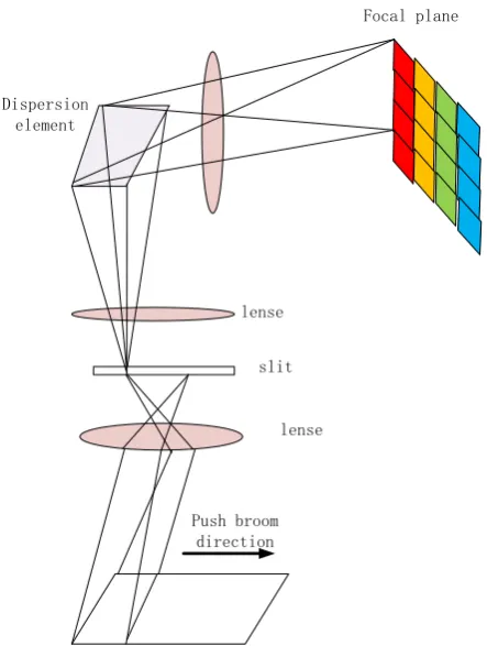
Push-broom imaging principle of scanning imaging spectrometer is shown as Figure 1 shows: through a slit in the directionparallel to the slit dimension and imaging in the vertical slit direction to obtain a two-dimensional target imaging [1].
3. Spectral Imaging with Linear Detector Imager System Model
3.1. System IntroductionFigure 1. Traditional push-broom imaging spectrometer.
technology. The code template has a special mathematical code form. The spatial information and spectral of the original target can be modulated with the code template, using the theory of compressive sensing. We can re-construct one-dimensional special information and one-dimensional spectral information from the map of alias-ing imagalias-ing. We can obtain the two-dimensional special information with the push-broom imagalias-ing model.
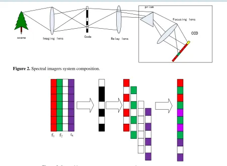
As Figure 2 shows, the system consists of (1) an objective lens, (2) a coded aperture, (3) relay lens, (4) dis-persion prism, and (5) a monochrome linear charge-coupled device (CCD) detector. The objective lens images the scene on to the plane of the coded aperture.
3.2. Code Process
The spectral imager with linear detector imager system realizes a single shot compressive spectral imaging sys-tem. As Figure 3 shows, it encoded both 1D spatial and 1D spectral information of objects through an aperture code projection that is captured after it propagates through a dispersive element, a linear detector then collects all light passing through the aperture and the dispersive element. It is important to emphasize that the code aperture pattern remains fix in the sampling process. Suppose that the scene or object is represented by f l x
( )
, [2], where l is the wavelength and x correspond to the spatial position, in discrete form it is denoted as fmk.Suppose that the code pattern is Cm [3].The term wm takes into account all possible noise source. Then the
signal in front of the array detector can be expressed by (1) [4]. Example
( ) ( ) m
m m k k m k
k
S =
∑
f + C + +ω (1)3.3. The Reconstruction Algorithm
TwIST (Two-step Iterative Shrinkage Thresholding) is an algorithm framework introduced by Bioucas-Dias and Figueiredo [5]. In the context of image reconstruction for a CASSI system, in this paper, we reconstruct the image
Dispersion element
Push broom direction
slit
lense lense
Figure 2. Spectral imagers system composition.
Figure 3. Spectral imagers on spectrum compressed.
of spectral imagers with linear detector imager system with TwIST. TwIST describes a solution as the solution to the generalized non-linear, unconstrained minimization problem:
2 1 2
argmin m
f =W S −HWθ′ +τ θ′ (2) Here the linear operator H represents the system forward model. Reconstruction of fmk is attained by
solving the optimization problem. The first term minimizes the difference between the model and the measure-ment Sm. The variable tau > 0 controls the level of sparsity attained in the reconstruction. The sparser the
source fmk, the better the performance of the reconstruction algorithm. In this work, the CS reconstruction
al-gorithm was used to solve the Equation (2). The above procedure tries to recover the overall data cube with only one measurement and hence it often yields a low SNR output performance.
Before recovering spectral data, spectra data should be reprocessed to be normalized. Normalized data can be directly used algorithm for recovering. Restoration of the accuracy of the results depend on the end of the itera-tion condiitera-tion.
( )
(
)
(
)
( )
1 0
1 1 1
t t t t
x x
x x x x
λ
λ
α α β β
+ −
= Γ
= − + − + Γ (3)
( )
(
T(
)
)
x x K y kx
λ ψλ
Γ = + − (4) Before restoration, we need to set two parameters, the balance to the noise function and the end of iterative threshold tol.
The termination function in defined as
(
)
( ) ( )
( )
11
1
, t t
t t
t
x f x f
C f f
x f
− −
−
−
= (5)
树
Imaging lens Code
scene Relay lens
prism
CCD
Focusing lens
The termination function is tol. We stop iterativing if C f
(
t,ft−1)
≤tol.The process for the algorithm is as following: (1) obtain the parameters β , α, τ.
(2) imaging initialization, enter the initial value f0, setting calculation tol, the corresponding objective
func-tion x f
( )
0 ;(3) deal with f0 for removing the noise, f1= Γλ
( )
f0 , use the noise function to get a new f , numericalnoise function is selected , minimizing the total variational method to obtain the corresponding objective func-tion, calculate x f
( )
1 ;(4) compare x f
( )
0 with x f( )
1 , if that the calculated result is correct, this time need to be adjusted to bal-ance parameters in noise function;(5) calculate f2 with f1 and f0, repeat step 1 - 3, then update f0 with f1, f1 with f2, the iteration
continues;
(6) the iteration does not stop until the function is less than tol, if C f
(
t,ft−1)
≤tol, the iteration stops, thenwe can obtain the data cube reconstruction.
4. Simulation
The test uses MATLAB to carry on the simulation and reconstruction. The process is as following.
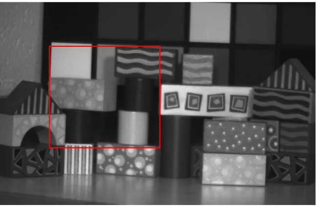
Firstly, from the realistic point of view, we choose online downloading remote sensing image as a simulation of ground targets. As Figure 4 shows, this multispectral database has 33 bands from 400 nm to 720 nm wave-length with a 10 nm step. The image size is 480 × 752 pixels. In the push-broom imaging simulation process, simulation design parameters as follows: the spectral range is 400 - 720 nm; spectrum channel number is 33, detector pixels is 280 × 1, Intercepting 256 × 280 pixels format as the push-broom scene spectrometer remote sensing image above.
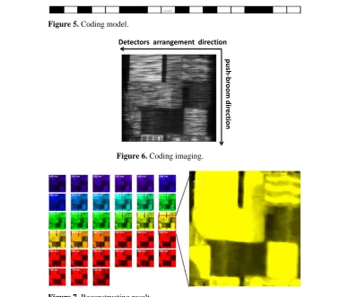
Secondly, simulate smashing on the CCD. Different from CASSI, ours system coded model is 1-dimen- sional. Be sure that spectral dispersion direction and detectors arrangement direction is consistent. Linear array detector will get aliasing information, and with the push-broom imaging process, the entire scene information will be obtained. Figure 5 and Figure 6 show the coding model and the smashing result on the CCD.
[image:4.595.137.461.486.697.2]Finally, with the prior information of the arithmetic coding model and algorithms, we can recover the spectral data cube from the aliasing image data. In our simulation, we choose TwIST for recovering for its accuracy and speed are all well. Figure 7 shows the result of image reconstruction.
Figure 5. Coding model.
[image:5.595.103.482.81.412.2]Figure 6. Coding imaging.
Figure 7. Reconstructing result.
5. Result
From above, we can see that spectral imagers with linear detector imager system on spectrum compressed can make use of a 1-dimension detector instead of a 2-dimension detector to get a 3-dimensional data cube, which includes both the spectral information and the spatial information of each ground object.
It can decrease the dimensions of the detectors and complexity of imaging system greatly. This work has im-portant and far-reaching theoretical significance and extensive applied values to improve the technique levels of digital remote sensing, and it can satisfy exigent requirements for remote sensing spectral images internally.
Acknowledgements
This work was supported by the National Natural Science Foundation of China (No. 11204014).
References
[1] Shen, Z. (2002) The Principle of the Spaceborne Hyperspectrum Imager. Spacecraft Recovery& Remote Sensing, 23, 28-34.
[2] Arguello, H. and Arce, G.R. (2011) Code Aperture Agile Spectral Imaging (CAASI). OSA Optics and Photonics Con-gress, 978-1-55752-914-5.
[3] Arguello, H., Ye, P. and Arce, G.R. (2010) Spectral Aperture Code Design for Multi-Shot Compressive Spectral Im-aging. OSA Optics & Photonics Congress, 978-1-55752-887-2.
[4] Wagadarikar, A.A., Pitsianis, N.P. and Sun, X.B. (2008) Spectral Image Estimation for Coded Aperture Snapshot Spectral Imagers. Proc SPIE, 7076, 7076-7076-02.
[5] Bioucas-Dias, J.M. and Figueiredo, M.A. (2007) A New TWIST: Two-Step Iterative Shrinkage, Thresholding Algo-rithms for Image Restoration. IEEE Trans Image Process, 16, 2992-3004.
http://dx.doi.org/10.1109/TIP.2007.909319
Detectors arrangement direction
pus
h-b
room d
irect