© 2018, IRJET | Impact Factor value: 6.171 | ISO 9001:2008 Certified Journal | Page 2634
MANUALLY OPERATED HAND MOULD DIE
Khan Farhan
1, Rajput Rushikesh
2, Mohite Kiran
3, Sonawane Vishal
4, S C Pardeshi
51,2,3,4 BE Student, Mechanical, SND COE & RC, Yeola Maharastra, India 5Asst. Prof. Mechanial, SND COE & RC, Yeola, Maharastra, India
---***---Abstract - Within the context of molds and dies
production, frequent changes in design and increased competitiveness require an overall optimized manufacturing process. The finishing process is typically composed of an accurate milling stage to manage shape deviations, followed by polishing operations to reach required surface roughness. In this project we had design a new type of connector which connects the existing cap with new filter. Due to this project we save the time and money to a larger extend. Injection moulding machine is one of the most widely used method for conversion of plastics into various end products application to wide range of plastic material.
Key words: Cavity Plate, Punch Plate, Guide pins, Injection
moulding.
1. INRODUCTION
Injection molding is a manufacturing technique for making parts from both thermoplastic and thermosetting plastic materials in production. Molten plastic is injected at high pressure into a mold, which is the inverse of the product's shape. After a product is designed, usually by an industrial designer or an engineer, molds are made by a moldmaker (or toolmaker) from metal, usually either steel or aluminium, and precision machined to form the features of the desired part. Injection molding is widely used for manufacturing a variety of parts, from the smallest component to entire body panels of cars.Injection molding is the most common method of production, with some commonly made items including bottle caps and outdoor furniture. Injection molding typically is capable of tolerances equivalent to an IT Grade of about 9–14. The most commonly used thermoplastic materials are polystyrene (low cost, lacking the strength and longevity of other materials), ABS or acrylonitrile butadiene styrene (a terpolymer or mixture of compounds used for everything from Lego parts to electronics housings), The main principle is to compress the plastic material in a heating chamber (barrel) with the help of plunger and induction coil convert plastic polymer into molten (semi-solid) state. Then the plastic polymer in predetermined quantity is forced through the nozzle into the die under pressure. After completing the process, final product is obtained from the die. We can use plastics, metals or alloys for this process. In our project we are using plastics polymers for making a connector which is going to connect the filter with the existing bottle cap. This machine is a prototype for producing small plastic
components. This injection moulding machine is very useful for the small scale industries because of its low manufacturing cost, low maintenance cost, no skilled worker is required. It can be recommended for small scale investors those who are willing to produce small plastic products.
2. DESIGN METHODOLOGY
This paper highlights a practical design procedure/ methodology of an injection molding die, adopted by analyzing the various parameters to produce a precious industrial component namely RAM component for an electrical transformer has been choked out in detail aspect which is as follows.
2.1 Design Methodology.
© 2018, IRJET | Impact Factor value: 6.171 | ISO 9001:2008 Certified Journal | Page 2635
2.2 Cad/cam for mould design
The architecture of mould design system is proposed based on practical design parameters and conceptual design stage mainly consist of concept generation and concept evolution cad/cam can help designer to speed up design for the lastic part and mould design process and reduce the long lead time.The mold has to be designed to produce good quality connector component considering the ease of manufacturability, assembly and positive ejection of the component within the minimal time and cost. The design of double cavity molding tool is carried out using software AUTO CAD.the detailed drawing of mould is prepared by AUTO CAD and it is used for manufacturing the tool and connector.the mould is manufactured as per drawing specification.the performance of tool is tried out and significantly the defects are troubleshooted.the mould flow analysis using AUTODESK MOULD FLOW software is carried out on a component to achieve a good quality mould before moulding and to check the manufacturbility of a moulding part.
The steps involved in the methodology followed for the manufacturing of mould design is as followed.
1) Definition of the problem. 2) Literature review.
3) Conceptual design and design calculations. 4) Mould flow analysis.
5) CAD modeling of a tool. 6) Tool manufacturing.
7) Assembly and tryout of a tool. 8) Cost estimation of a tool.
2.PROBLEM DEFINITION
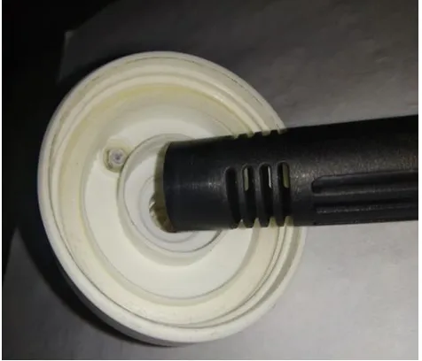
[image:2.595.316.554.199.403.2] [image:2.595.48.274.560.738.2]Fig.2.1 existing bottle cap and filter.
Fig.3.2 shows the new filter and the existing bottle cap.the diameter of this new filter is reduced to a desired extent,because of the reduction in the diameter of the filter the required volume of the water is achieved.the main problem is that,the diameter of the existing cap and the diameter of the new filter is different so they do not get connected.So we are going to design the connector which is going to connect the new filter with the existing cap.
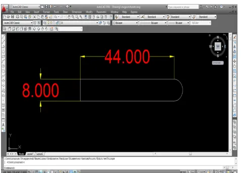
Fig.2.2 New filter and existing bottle cap.
Fig.3.2 shows the new filter and the existing bottle cap.the diameter of this new filter is reduced to a desired extent,because of the reduction in the diameter of the filter the required volume of the water is achieved.the main problem is that,the diameter of the existing cap and the diameter of the new filter is different so they do not get connected.So we are going to design the connector which is going to connect the new filter with the existing cap.
3. CONCEPT OF PROJECT
© 2018, IRJET | Impact Factor value: 6.171 | ISO 9001:2008 Certified Journal | Page 2636 material from which the mould is going to be
manufactured will be of mild steel and p20 (2738) steel.In this project we are going to manufacture as follows.
1)Cavity Plate. 2)Punch Plate. 3)Cavity guide pin 4)Bush.
5)Cavity side backplate. 6)Punch side backplate. 7)Runner.
8)Gate.
4. WORKING PRINCIPLE
4.1. Punch Plate.
Fig 4.1 punch plate
The punch plate is one of the main component in the connector designing.it consist of the total eight holes, four of them are going to carry guide pins on which the mould is going to function, two of them are for the ejector pins which helps to release the article from the mould. the remaining two of them will be for bolting which is required to joint the punch support plate. the punch plate is out centered in order to decrease the runner the length, because of the reduction in runner length, the molten plastic will take much less time to enter the mould and it will also reduce the plastic consumption per each shot of the machine. side runner is provided to it. In this plate the punch is going to be fitted externally in order to reduce the metal consumption. Also the advantage of fitting the punch externally is it can be replaced if need occurs.
4.2 Punchide backplate.
Fig4.2 Punchside back plate.
The punchside back plate is only going to support the punch plate.it is going to connect the punch plate with it by means of bolting.the head of the bolt will be on the backside of this plate.the guide pin holes will be tapered in order to make the function of the mould rubbfree.
4.3 Cavity Plate.
Fig4.3Cavity plate.
© 2018, IRJET | Impact Factor value: 6.171 | ISO 9001:2008 Certified Journal | Page 2637 4.4Cavity guide pin.
Fig 4.4 Cavity guide pin
The cavity guide pins will be used to connect the splitted cavity part into a single cavity. the diameter of the guide pins will be tapered because of the continuous function of the cavity. It will be designed in such a way that minimum friction will be there and due this the life of the hand mould die will be longer.
4.5 Cavityside back plate
[image:4.595.42.281.101.272.2]The cavityside back plate is designed to support the cavity plate.due to the continuous function of the cavity plate it is possible that it may lead to a wearing of it, in order to encounter this problem cavityside back plate is designed. the backside of the cavity plate is raised and the frontside of the cavityside back plate is hollowed. the raised part of the cavity closed for the injection of molten plastic. when the injection work is finished, the cavity plate and cavityside back plate is dismantled to split the cavity plate, and the final object is taken out from the mould.
Fig.4.5 Cavityside backplate.
5 Gate and runner.
The runner which is going to be used in this mould design will be side runner. there are many types of gate like direct sprue gate, side runner gate, fan gate, pinpoint gate, disk gate, ring gate, film gate, tab gate, submarine gate etc.we are going to design the side runner gate because of the company requirement.
6 Shrinkage ratio.
Moulding shrinkage ratio.
Molding shrinkage will occur in the process of cooling solidification of molten resin filled at the cavity, so relatively big molding shrinkage will occur in the case of crystalline resin like PBT resin. Molding shrinkage ratio depends on mutual effect of many factors, and the major factors will be the followings.
1.Resin temperature. 2.Mold temperature. 3.Injection pressure. 4.Injection speed. 5.Injection time
6.Molded product thickness.
7.Filling material, shape of the reinforcing material, and content.
7. SUMMARY
As can be seen in the working principle above. The requirement of the company is fulfilled by the designing of die.
8. RESULT
The company called Premsons Plastics Private Limited has given us the project to design and manufacture the manually operated hand mould die of a connector.We had designed and will be manufacturing the mould according to the design which we had produced in this paper.With the designing of this connector mould, The companys requirement is fulfilled.
9.SPECIAL FEATURES OF PROJECT
© 2018, IRJET | Impact Factor value: 6.171 | ISO 9001:2008 Certified Journal | Page 2638
10. CONCLUSION
In this project instead of making injection mould die for a bottle cap which is already existing we are desiging and manufacturing manually operated hand mould die for the production process of connector which will successfully connect the new filter with the existing bottle cap.
Due to this achievement company will be able to reduce its cost and time significantly.
ACKNOWLEDGEMENT
While presenting this project, we are glad to convey our thanks to the people who guided us and help us at every stage of our project. We deeply acknowledge the support of our Head of Department Prof. Bhamre V.G. for his valuable input and constant guidance in successful completion of our project. We also thank our project guide Prof. Pardeshi S.C and giving their valueable time and guiding us throughout in the development of our project.
We express our sincere gratitude to the librarian who has provided her co-operation towards the completion of reference work. Most importantly we would like to express our sincere gratitude towards our Friends & Family for always being there when we needed them most.
REFERENCES
1). Shaik Mohamed Mohamed Yusoff, University Technology Malaysia, 2004, “A Plastic Injection Moulding Process Characterization using Experimental Design Technique: A case study.
2). Warner Jan de putter, Hardenberg, Netherland, “Removal of Injection Moulded Product”.
3). Abdul Azwan Bin Abdol Zahar, 2009, “Effects of Injection Moulding Gate Mechanism on parameters machining and defects of book tray”.
4). Warner Jan de putter, Hardenberg, Netherland, “Removal of Injection Moulded Pro duct”.
5). Mould flow, 2004, “Injection Moulding Automation: From Concept to Flawless Volume Production in One Go”.
BIOGRAPHIES
Khan Farhan S. SND COE Yeola, Pune University, Department of Mechanical Engineering.
Rajput Rushikesh D. SND COE Yeola, Pune University, Department of Mechanical Engineering.
Mohite Kiran. SND COE Yeola, Pune University, Department of Mechanical Engineering.
Sonawane Vishal S. SND COE Yeola, Pune University, Department of Mechanical Engineering.