© 2017, IRJET | Impact Factor value: 5.181 | ISO 9001:2008 Certified Journal
| Page 2217
DS-UWB signal generator for RAKE receiver with optimize selection of
pulse width
Twinkle V. Doshi
EC department, BIT, Vadodara, Gujarat, India
---***---Abstract -
This paper presents discussion on the DS-UWBsignal transmitter and the selection of transmitter paramerts to reduce interference and to improve the performance of receiver. The transmitter provides the DS-UWB signal with the specific parameters and then it is supposed to propagate through the channel having certain characteristics which are listed.
Key Words: DS-UWB, Multipath Channel, Transmitter
1 Generation of DS-UWB signals
[image:1.595.41.293.434.515.2]DS-SS is a well-known digital modulation method. In this technique the message signal modulates the bit sequence known as the PN sequence. This modulated PN sequence is converted into pulses of very small duration (large bandwidth). The bit of the PN sequence is replaced by many small pulses and thereby increasing the bandwidth. Due to large bandwidth it becomes more immune to noise.
Figure 1 Transmission Scheme for PAM DS-UWB Signal [2]
As shown in the figure 1, let s= (…, s0, s1,…, sk, sk+1,...) is the
binary sequence to be transmitted. The bitrate of generated sequence is Rb=1/Tb bits/s. Then the sequence is forwarded
to the code repetition coder which repeats each bit Ns times and generate a binary sequence a* = (..., s0, s0, ... s0, s1, s1, ..., s1,
sk, sk, ... sk, sk+1,sk+1, ... sk+1) at a rate of Rcb=Ns/Tb=1/Ts bits/s,
the purpose of repeating the same bit is to add robustness during transmission [1]. It is known as an (Ns, 1) code repetition coder [2].
After the code repetition coder, the sequence is passed to the binary (+/-) series generator, which converts the a* sequence into a positive and negative valued sequence a =
(..., a0, a1... aj, aj+1 ...), i.e.(aj =2
a
j *-1,-<j<+) [2] and feeds to the transmission coder. The function of the transmission coder is to apply a binary code c = (…, c0, c1… cj, c j+1…)
consisting of 1’s and period Np to the sequence a = (..., a0,
a1… aj, aj+1...), that produces a new sequence d=a*c. This
sequence is self-possessed of elements d = aj*cj. Here d is a 1’s sequence same as that of a and it is generated at a rate Rc= Ns/Tb = 1/Ts bits/s. Sequence d enters a third system, the
PAM modulator, which generates a sequence of unit pulses [Dirac pulses (t)] at a rate of Rp= Ns/Tb = 1/Ts pulses/s. The
output of the modulator enters the pulse shaper filter with impulse response p(t). In traditional DS-SS systems, the impulse response p(t) is rectangular pulse with duration Ts.
In the DS-UWB case p(t) is the pulse with a duration much smaller than Ts.
The signal s(t) at the output of the cascade of the above system can be expressed as follows:
(1) The bit interval or bit duration, that is, the time used to transmit one bit Tb, is Tb=NsTs.
2. Selection of parameters for transmitter and
discussion
Table 1 shows the parameters selected to generate DS-UWB signals. It is followed by the reasons for their selection.
Table 1 Simulation parameters for transmitter
Parameters Value
Average transmitted power
(dBm) -30
Sampling frequency (Hz) 10e9
Number of the bits
generated by the source 2000
Frame time: average pulse
repetition period (s) 30e-9
Pulse duration (s) 0.323e-9
Shaping factor for the pulse
(s) 0.2e-9
)
(
)
(
sj
j
p
t
jT
d
t
s
[image:1.595.303.562.511.791.2]© 2017, IRJET | Impact Factor value: 5.181 | ISO 9001:2008 Certified Journal
| Page 2218
Transmitted signal format DS-UWB (BPSK)Channel model Standard IEEE 802.3.15a Channel - (CM1, CM2, CM3 and
CM4) Length of training sequence 2000
Monopulse type Gaussian 1st derivative
before transmission
Bit duration (Tb)
(1 bit consists of 10 pulses)
3.23 e-9
Pulses per frame (Ns)
(1 bit = 1 frame)
10
Bit rate (Rb=1/Tb) 300 Mbps (approx.)
The transmitted power is kept low because regulatory rules specified by FCC depict indoor and outdoor spectral masks. The UWB transmitter must satisfy FCC mask in order to diminish the interference with other narrowband technologies operating in the same frequency band. To comply with FCC restrictions considerably low power transmission is selected.
The simulation uses a binary generator to feed the system with random data. In order to save computing resources, the number of data bits for the simulation is set at 2000 as shown in table 1, that results into decrease in time required for simulation.
Selection of Gaussian pulse and the pulse width is justified in section 3.1.
Four sets of parameters are given, to characterize the statistical properties of different channels [2]. In particular, the following propagation conditions are considered:
1) CM1: Line of sight (LOS) channel with a transmitter-receiver distance between 0 and 4 m.
2) CM2: NLOS channel with a transmitter-receiver distance between 0 and 4 m.
3) CM3: NLOS channel with a transmitter-receiver distance between 4 and 10 m.
4) CM4: Extreme NLOS channel (RMS delay spread of 25 ns).
In this model, from the above mentioned channels, one by one channel will be assigned to the user. In this scheme, the path loss attenuations are assumed proportional to dγ where
d is the transmitter-receiver distance and γ is power decay factor. The parameter γ is set equal to 2 for LOS channel and 3.5 for NLOS ones [2].
[image:2.595.310.561.152.242.2]3.
DS-UWB time domain representation
Figure 2 Time domain representation of DS-UWB [9] As shown in figure 2 each information bit is represented by Ns number of impulses. In the presented scheme, one symbols represented by two bits as BPSK scheme is involved. Hence one symbol represented by two frames 2Tf
and each frame consists of 10 numbers of pulses. Here it is assumed Ns=10, pulses are having pulse width of Tm.. In
DS-UWB scheme usually the chip time Tc is equal to the pulse
duration [9].
DS-UWB employs sequences of UWB pulses (analogous to “chips”) just as the SS techniques generate the bit sequence [3]. A specific pseudo random sequence is devoted to individual user which then modulates the UWB pulse train. The resulting signal will then be an uninterrupted transmission of UWB pulses whose number depends on the length of the pulse itself and the bit rate defined by the system [4].
3.1 Selection of Gaussian monopulse and its pulse width
© 2017, IRJET | Impact Factor value: 5.181 | ISO 9001:2008 Certified Journal
| Page 2219
-0.5 -0.4 -0.3 -0.2 -0.1 0 0.1 0.2 0.3 0.4 0.5
-0.5 0 0.5 1
time(ns)
N
o
rm
a
liz
e
d
A
m
p
lit
u
d
e
[image:3.595.315.566.100.567.2]UWB pulse Gaussian Doublet
Figure 3 Gaussian doublet in time domain
0 5 10 15 20 25 30 35 40 45 50
-400 -350 -300 -250 -200 -150 -100 -50 0
FREQUENCY(GHz)
P
o
w
e
r(
d
B
[image:3.595.49.272.103.283.2])
Figure 4 Gaussian doublet in frequency domain The waveform shown in figure 3 is an example of idealized UWB waveform. The transmitting antenna generally does differentiation of the time waveform presented to it. As a result, the transmitted pulse does not have a DC (direct current) value—the integral of the waveform over its duration must equal zero. These conditions are true in the case of waveform shown in figure 3 hence it is a probable model for a UWB waveform; it is most suitable in the UWB environment as it has even symmetry about the peak value also [6]. Figure 4 represents the Gaussian doublet in frequency domain. It shows that the center frequency is approximately 3 GHz. Here first order Gaussian monopulse is employed for short pulse transmission. This appears at receiver as Gaussian doublet.
After deciding the pulse shape, the second important parameter, the pulse width needs to be decided. The greater the value of pulse width, the
closer the frequency content of the pulse will be to that of the mask [7], and the greater will be the number of orthogonal pulses which fit the mask. However, the pulse width increases, the data rate goes down. Thus there is a trade-off between the two variables.
If the selected pulse width is too small then there is a possibility that the delay spread is greater than the symbol duration results in ISI.
UWB transmitter emits very short duration Gaussian monocycles. In UWB, pulses have monocycle pulse widths of between 0.20 and 1.50 nanoseconds [5].
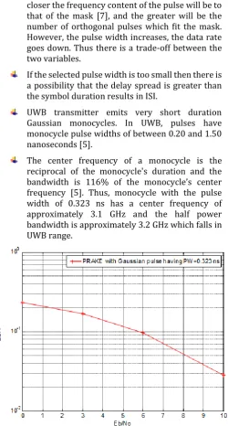
The center frequency of a monocycle is the reciprocal of the monocycle's duration and the bandwidth is 116% of the monocycle’s center frequency [5]. Thus, monocycle with the pulse width of 0.323 ns has a center frequency of approximately 3.1 GHz and the half power bandwidth is approximately 3.2 GHz which falls in UWB range.
[image:3.595.48.271.322.499.2]© 2017, IRJET | Impact Factor value: 5.181 | ISO 9001:2008 Certified Journal
| Page 2220
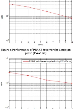
Figure 6 Performance of PRAKE receiver for Gaussianpulse (PW=1 ns)
Figure 7 Performance of PRAKE receiver for Gaussian pulse (PW=1.24 ns)
In the figure 5, figure 6 and figure 7 the effect of varying the pulse width on performance of PRAKE receiver is shown. The effect of variations in the pulse width on the performance of PRAKE receiver is shown by the plot of BER versus Eb/No. Three values are selected here (PW= 0.323 ns,
1 ns and 1.24 ns). From the figures it can be concluded that the performance of PRAKE receiver is enhanced for the pulse width of 0.323 ns so it is chosen for the simulation.
[image:4.595.312.555.116.217.2]4 Simulation result of PAM-UWB transmitter
Figure 8 Signal generated by PAM-UWB transmitter This simulation is based on the block diagram given in figure 1. It receives an input stream of bipolar values and generates a train of Dirac pulses. All pulses are equally spaced in time with a fixed pulse repetition period Ts. The
amplitude of each pulse is determined according to both the DS code and the PAM scheme. Figure 8 shows the signal generated by the PAM-UWB transmitter. It shows the sample signal which is generated for 10 bits. These signals consist of ten groups each having ten pulses. Each group is associated with one single bit generated by the source. The group of pulses which represents 0 are inverted in amplitude compared to the group of pulses which represents 1.
Figure 9 Power Spectral Density at different stage of transmitter for 2nd derivative of Gaussian monopulse
(PW=0.323 ns)
[image:4.595.36.292.138.519.2] [image:4.595.312.570.397.561.2]© 2017, IRJET | Impact Factor value: 5.181 | ISO 9001:2008 Certified Journal
| Page 2221
-25 -20 -15 -10 -5 0 5 10 15 20 25
0 0.2 0.4 0.6 0.8 1 1.2x 10
-15
frequency [GHz]
P
o
w
e
r
S
p
e
c
tr
a
l D
e
n
s
ity
[
V
2/H
z
[image:5.595.54.279.103.190.2]]
Figure 10 PSD of PAM-DS-UWB signal
The figure 10 shows the simulation for evaluation of the PSD of DS-UWB signal. The signal under examination is characterized by the transmission of Np=Ns=10 pulses per
bit. All pulses are equal in time with a pulse repetition period Ts. Each pulse has the second derivative Gaussian shape with
a maximum length of 0.323 ns.
The envelope of the PSD has the Gaussian shape of the Fourier transform of the basic pulse [8]. The transmitter power concentrates on the peaks located at multiples of 1/Ts. This is due to the effect of code spectrum. The code
spectrum is composed by the superposition of several sinusoids in the frequency domain, and the period of the sinusoid with the highest amplitude is exactly 1/Ts.
5. Conclusion
The 2nd derivative of Gaussian pulse shape is selected so that
it satisfies FCC emission mask and occupies maximum bandwidth in UWB range. Gaussian monocycle with pulse width equals to 0.323 ns is a good choice as it met the given criterion. The Gaussian first derivative is used for transmission and it appears as Gaussian doublet (Gaussian second derivative) after differentiation done by transmitting antenna. The pulse width is so selected that the frequency falls in the UWB range (3.1 GHz -10.6 GHz). The proposed system generates the DS-UWB signal with 3.1 GHz frequency. With different pulse width, of the Gaussian pulse, the performance of PRAKE receiver is evaluated. It shows good performance with the pulse width of 0.323 ns. With further increase in PW the data rate decreases, so appropriate choice of PW is important.
Using the selected parameters the DS-UWB signal was generated and maximum bit rate of 300 Mbps could be obtained with proposed scheme.
.
References
[1] Rappaport, Wireless Communications Principles and Practice, Prentice Hall, New Jersey, 1996, pp. 336-338.
[2] Maria-Gabriella Di Benedetto, Guerino Giancola,” Understanding Ultra Wide Band Radio Fundamentals”, Prentice Hall; 1st edition, June 27, 2004
[3] Mosa Abu-Rgheff, 2007, Introduction to CDMA wireless communication.
[4] M.Z. Win and Z.A. Kostic, "Virtual path analysis of selective RAKE receiver in dense multipath channels," IEEE Communications Letters, vol.3, no.11, pp.308-310, Nov. 1999.
[5] V. Niemela, M. Hamalainen, J. Iinatti and A. Taparugssanagorn, "P-RAKE receivers in different measured WBAN hospital channels," Medical Information & Communication Technology (ISMICT), 2011 5th International Symposium on , vol., no., pp.42,46, 27-30 March 2011
[6] F. am re -Mireles, "On the performance of ultra-wide-band signals in Gaussian noise and dense multipath," Vehicular Technology, IEEE Transactions on , vol.50, no.1, pp.244,249, Jan 2001 [7] S. C. Surender and R. M. Narayanan, "UWB
Noise-OFDM Netted Radar: Physical Layer Design and Analysis," in IEEE Transactions on Aerospace and Electronic Systems, vol. 47, no. 2, pp. 1380-1400, April 2011.
[8] ETSI TR 101 994-1 V1.1.1 (2004-01), “Electromagnetic compatibility and adio spectrum Matters (ERM); Short Range Devices (SRD); Technical characteristics for SRD equipment using Ultra Wide Band technology (UWB) Part 1: Communications applications”, Technical report, Sophia Antipolis Cedex - FRANCE, 2006.

![Figure 2 Time domain representation of DS-UWB [9]](https://thumb-us.123doks.com/thumbv2/123dok_us/8164586.806832/2.595.310.561.152.242/figure-time-domain-representation-ds-uwb.webp)