© 2017, IRJET | Impact Factor value: 5.181 | ISO 9001:2008 Certified Journal | Page 864
CONICAL FLUIDIZED BEDS - CASE STUDY FOR A GAS SOLID SYSTEM
INVOLVING COARSE PARTICLES
Rajesh Katiyar
Associate Professor, Chemical Engineering Department, Harcourt Butler Technical University, Kanpur, India
---***---
Abstract -
Conical fluidized beds offer distinctadvantages over columnar fluidized beds in dealing with particles of broad size distribution as well as for the particles which are cohesive in nature. It is really very advantageous in conical beds with higher gas velocity over the grid ensuring elimination of chances of bed de-fluidization, whereas the lower velocity at the top reducing elutriation. Two-dimensional conical beds with cone angles of 20.5° and 10° were utilized. Using air as fluidizing medium, the particles which were fluidized were silica sand of size (-180 + 150 µm). The regimes that occurred during the increasing fluidization velocity as well as the regimes of decreasing fluidization velocity have been observed. Parameters of stagnant bed height and cone angle of bed have been studied for their effect on maximum pressure drop, minimum velocity of partial fluidization, pressure drop corresponding to minimum velocity of full fluidization and minimum velocity of full fluidization.
Key Words: Conical fluidized bed, cone angle,pressure drop, fixed bed, fluidization velocity, Ergun equation, particle size, initial bed height.
1. INTRODUCTION
A fluidized bed is formed when the particles in the bed are in dynamic equilibrium. The fluid drag force and the buoyancy force are exerted in the upward direction against the gravitational force, which pulls the particles downward. If we compare the fluidization in a columnar bed to that of a tapered bed, then the drag force is constant at any position of a columnar bed of uniform particles. However it decreases in the upward direction in a tapered or conical bed accompanied by the reduction in the superficial velocity of the fluid. Hence, particles of the lower parts of the bed would first be fluidized upon an increase in the flow rate, whereas the particles at the upper part of the bed tend to remain static. Thus phenomenon of partial fluidization is observed and typical to tapered fluidized bed [1]. In the processes of fuel combustion and gasification, roasting of ores as well as waste heat recovery, the conical packed beds have potential applications [2]. Highlighting on the application of tapered fluidized beds for biochemical reactions and biological treatment of waste water, the advantages of the tapered beds over the columnar beds have been discussed [3]. The voidage in a tapered fluidized bed of large apex (cone) angle is smaller and its dependence on velocity is
less than that for a columnar (cylindrical) fluidized bed. Also, it is important to note that apart from handling the wide particle size distribution an intense exothermic reaction can be handled properly in a conical bed. The operations of conical bed are smooth with the absence of any instability. In the conical fluidized beds, a velocity gradient exists in the axial direction, leading to unique
hydrodynamic characteristics [4,5].
1.1 Improving fluidization of cohesive particles
When fluidization of cohesive particles is attempted, it leads to plug flow and channeling. As per Geldart classification, the cohesive particles are placed in group C. Difficulty in fluidization of these particles is related to the inter-particle adhesive forces which cause agglomeration and bridging between agglomerates. Examples are starch granules, flour, pigments, etc. Since cohesive particles can only be fluidized in the form of agglomerates, attempts have been made in improving the fluidization quality of the cohesive particles by using external forces, like baffles, outside vibration, acoustic or magnetic fields. Adjustment of the cohesiveness of the particles can be attempted by modifying the surface of particles or by addition of other particles. Compared with other methods, the advantage of adding particles is that no additional equipment or device is required [6,7].
1.2 Coarse and fine particle fluidization
Particle size and particle size range are important in fluidization. For coarse particles (of Geldart-D zone), three flow regimes, which are fixed bed, partially fluidized bed and fluidized bed have been observed successively with the increase of superficial gas velocity in a conical bed. Three cone angles of the bed were utilized for the study. It has been observed that the bed cone angle and the particle bed height are the main factors influencing the regime transition and hydrodynamics of the particle bed. In the fixed bed regime, the total pressure drop and the local pressure drop can be predicted by Ergun's equation [8].
© 2017, IRJET | Impact Factor value: 5.181 | ISO 9001:2008 Certified Journal | Page 865
comparison with Geldart-D powder, partially fluidized bedregime disappears [9].
2. Hydrodynamic characteristics
Studies have been reported by researchers to determine the factors affecting minimum fluidization velocity and maximum pressure drop. Some of these results are concerned with regular particles. It has been stated about the investigations that have been carried out regarding fixed bed pressure drop calculations, flow regimes, incipient condition of fluidization, void distribution and bed expansion calculations [5].
2.1 Development of models for conical bed
systems utilizing fluidization of solids
Studies related with development of a model for maximum pressure drop at incipient fluidization condition of a tapered fluidized bed has been carried out and the model developed is based on Ergun's equation. Here friction between the particles and the wall has been neglected [3]. Theoretical model has been developed for minimum fluidization velocity and for the pressure drop in a packed bed of spherical particles for gas-solid systems in a conical vessel [2].Characteristics of solid-liquid fluidization were studied in a tapered bed and theoretical models have been developed for the prediction of minimum fluidization velocity and maximum pressure drop. Experiments were carried out for the spherical particles and the model development is based on the dynamic balance of forces exerted on the particle [1].
On the basis of these models and on the studies carried out on conical fluidized beds, models were developed for gas-solid systems for spherical coarse and fine particles [8,9]. Looking towards development of a generalized correlation for the calculation of minimum fluidization velocity and maximum pressure drop in a tapered fluidized bed an empirical dimensionless correlation has been developed for predicting the minimum fluidization velocity and maximum pressure drop for regular and irregular particles of gas-solid systems [5]. Parameters which have been considered are particle diameter, particle density, tapered angle, porosity and sphericity. Parameter of bed height has not been considered, though the pressure drop also depends upon the bed height. Authors have compared the applicability of the new model to that of existing models from literature.
3. Materials and methods
3.1 Experimental set-up
Fluidization columns were fabricated from perpex to allow visual observations of the fluidization. The experiments were performed with two-dimensional columns having tapering angles of 10° and 20.5°. Their thickness was 1.7 cm and height in each case was 0.5 m. The cross-section at bottom was 2.75 x 1.7 cm. To measure the pressure drop through bed, pressure tap was installed on the wall along the centerline of each column immediately above the distributor. The tapping was connected to U tube manometer. Gas distributor was a polymer type mesh. Air was supplied by a blower whose speed was varied by a variable voltage supplier. Gas flow rate was determined by means of venturi-meter which was connected to the U tube manometer. Provision of measuring the bed height was through a graduated scale. Silica sand of size (-180 + 150 µm) was used for fluidization and de-fluidization studies.
3.2 Experimental procedure
The experiments were carried out under ambient conditions. For conducting experiments, the conical bed was charged with material to a fixed bed height. Initially the bed was fully fluidized by increasing the flow rate of air and subsequently the flow rate was gradually reduced to zero to a stage where the material was settled to form a fixed bed. This was the initial fixed bed height and the procedure was used to obtain reproducible results.
During the performance of an experimental run, the flow rate of air through the column was increased incrementally. When a stable state was established after each increment, records were made of the readings on the manometers. An experimental run was initiated by increasing the flow rate to fluidize the bed and then by decreasing the flow rate to defluidize it. Visual observations were made during the experiments in addition to the pressure drop and flow rate measurements. Gas velocity has been expressed on the basis of inlet area of the bed and manometer readings corresponding to bed pressure drops have been plotted against corresponding superficial velocities at the inlet.
4. Results and discussion
© 2017, IRJET | Impact Factor value: 5.181 | ISO 9001:2008 Certified Journal | Page 866
the silica sand particles of the specific size under study,three distinct regimes are observed in the increasing fluid velocity cycle. These regimes are of fixed bed, partially fluidized bed and fully fluidized bed. These flow regimes are similar to as reported by S. Jing et al., 2000[8].
Plot -1: Effect of superficial gas velocity on pressure drop In bed with cone angle of 20.5°
Initially as the superficial gas velocity is relatively low, the stagnant height of the particle bed remains unchanged as at the beginning. The total pressure drop increases upto the maximum value at peak point. Upto peak point we have the fixed bed regime and the peak point corresponds to minimum velocity of partial fluidization. With the increase of superficial gas velocity, total pressure drop decreases and it is observed that there is no appreciable change in the stagnant height of the conical bed. Thus after the peak point there is downward variation in the pressure drop upto the stage when the pressure drop becomes nearly constant. Till this stage the regime of partially fluidized bed is observed in which there is no appreciable change in the stagnant height of the conical bed. After this stage the beginning of fully fluidized bed takes place and in this regime the pressure drop stays nearly constant. The beginning point of fully fluidized bed corresponds to the minimum fluidization velocity for full fluidization.
Thus three distinct regimes as well as the minimum velocities of partial fluidization and for full fluidization can be identified. The experimental pressure drop versus velocity data for coarse particles of same size range obtained from the two-dimensional tapered fluidized bed with cone angle of 10° has been shown in plot 2. Initial bed height was 5 cm. The fluidization and de-fluidization trends that have been observed are nearly similar to that observed for coarse particle fluidization in bed with cone angle of 20.5°.
Plot -2: Effect of superficial gas velocity on pressure drop In bed with cone angle of 10°
Plot -3: Effect of stagnant bed height of the conical bed (θ = 20.5°) on fluidization with coarse particles
Plot 3 is showing the effect of stagnant height (initial bed height) of the conical bed on flow regime in the case of the bed with cone angle of 20.5°. There are three regimes and the values of maximum pressure drop, minimum velocity of partial fluidization, minimum velocity for full fluidization and pressure drop corresponding to minimum velocity of full fluidization increase with increasing stagnant bed height. Three different stagnant bed heights that were studied are 5, 7 and 9 cm respectively.
0 20 40 60 80 100 120 140 160
0 1000 2000 3000 4000 5000 6000 7000
Defluidization Fluidization
Pres
s.
dr
op(
dy
ne/
cm
²)
Ugo(cm/s)
0 10 20 30 40 50 60 70 80
0 1000 2000 3000 4000 5000 6000
Fluidization Defluidization
Press.
dr
op(
dy
ne/
cm
²)
Ugo(cm/s)
0 20 40 60 80 100 120 140
0 2000 4000 6000 8000 10000 12000 14000
9 cm bed height 7 cm bed height 5 cm bed height
Pr
ess
.
dr
op(
dy
ne/
cm
²)
© 2017, IRJET | Impact Factor value: 5.181 | ISO 9001:2008 Certified Journal | Page 867
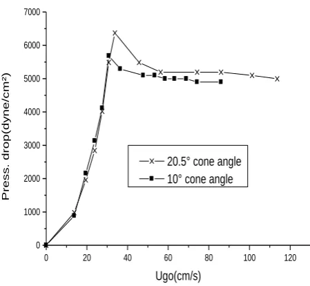
Plot -4: Effect of cone angle of conical bed with stagnantheight 5 cm on fluidization with coarse particles
[image:4.595.49.274.112.319.2]Plot 4 is showing the effect of the cone angle of the conical bed on flow regimes, where the two dimensional tapered beds with cone angles of 10° and 20.5° have been utilized for study under stagnant height of 5 cm with coarse particles. There are three regimes for the two cone angles and the values of maximum pressure drop, minimum velocity of partial fluidization, pressure drop corresponding to minimum velocity of full fluidization and minimum velocity of full fluidization increase with the increase of cone angle. Thus the cone angle in a two-dimensional conical fluidized bed plays an important role in deciding about the operation range.
Figure -1: Two dimensional conical bed geometry
Pressure drop in a fixed bed in a two dimensional tapered bed can be modeled theoretically utilizing Ergun’s equation. When a liquid or gas is passed at very low velocity up through a bed of solid particles, the particles do not move and the drop in pressure is given by Ergun
equation. Figure 1 is the front view of the bed where b is the width (2.75 cm) and a is the depth (1.7 cm). These dimensions as well as the other details have been mentioned earlier in sub-section 3.1.
From the equation of continuity, we have
axb
u
b
H
a
u
go g
2
tan
2
Where,
2 tan
2H
b X
a = depth of two dimensional tapered bed
b = width of two dimensional tapered bed
u
go= superficial gas velocity at gridH = axial distance from the distributor
u
g= gas velocity
Θ = apex angle of tapered bed
The gas velocity at the axial distance H, from the distributor can be expressed as,
b H u
H b
b u
ug go go
2 tan 2 1 2 tan
2
From Ergun’s equation,
s p
s g f
p s
s g f
d u u d
u u dH
dp
2
3 2
3 2
1 75 . 1 1
150
The fluid and solid parameters involved in Ergun equation are:
ε = bed voidage
µ
f= gas viscosity
ρ
f= gas density
ɸ
s = sphericity for the solid particled
p = diameter of particleAs us = 0, we have
0 20 40 60 80 100 120
0 1000 2000 3000 4000 5000 6000 7000
20.5° cone angle 10° cone angle
Pres
s.
dr
op(
dy
ne/
cm
²)
© 2017, IRJET | Impact Factor value: 5.181 | ISO 9001:2008 Certified Journal | Page 868
s pg f p s g f
d
u
d
u
dH
dp
2 3 2 3 21
75
.
1
1
150
Using K1 and K2 as,
23 2 1
1
150
p s fd
K
p s fd
K
3 21
75
.
1
2 2 2 12
tan
2
1
2
tan
2
1
b
H
u
K
b
H
u
K
dH
dp
go go
Let,b
t
2
tan
2
, and on substituting the value of t inabove equation,
22 2 1
1
1
tH
u
K
tH
u
K
dH
dp
go go
--- (1)Proceeding with integrating the equation (1) along the bed height,
tH
K
u
tH
dH
u
K
dp
H H go go p
0 2 0 2 2 1 01
1
1
1
go
HH go p
tH
t
u
K
tH
t
u
K
P
0 2 2 0 1 01
1
1
ln
1
On imposing the appropriate limits,
∆
tH
t
t
u
K
tH
t
u
K
P
go go1
1
1
1
ln
1
2 2 1Or, ∆
tH
t
u
K
tH
t
u
K
P
go go1
1
1
1
ln
2 2 1On substituting the value of
b
t
2
tan
2
, in the aboveequation, we have the expression for pressure drop in a fixed bed in a two dimensional tapered bed which has been shown earlier geometrically:
b
H
bu
K
b
H
b
u
K
P
go go2
tan
2
1
1
2
tan
2
2
tan
2
1
ln
2
tan
2
2 2 1
While studying the effect of superficial gas velocity on pressure drop, it has been observed that the total pressure drop increases upto the maximum value at peak point and upto this the fixed bed regime exists. The transition from fixed bed to partially fluidized bed occurs at this point and the total pressure drop is a function of superficial gas velocity.
5. CONCLUSIONS
For the coarse particles fluidization, the experimental results show that the bed cone angle and the particle bed height are the main factors influencing the regime transition. Three different flow regimes that are observed are fixed bed, partially fluidized bed and fully fluidized bed in the increasing fluid velocity cycle. In the decreasing fluid velocity cycle the pressure drop decreases continuously. The operation range for the fixed bed regime becomes wider by increasing the cone angle and the stagnant bed height. The results obtained would be useful during studies with other particles of broad size range, particles carrying certain degree of cohesiveness and finding out means of fluidizing cohesive or fine particles along with specific coarse additives.
ACKNOWLEDGEMENT
© 2017, IRJET | Impact Factor value: 5.181 | ISO 9001:2008 Certified Journal | Page 869
REFERENCES
[1] Y. Peng, L. T. Fan, "Hydrodynamics characteristics of
fluidization in liquid-solid tapered beds", Chem. Engg. Science, vol. 53(3), 1997, 2277-2290.
[2] K. C. Biswal, T. Bhowmik, G.K. Roy, "Prediction of
pressure drop for a conical fixed bed of spherical particles in gas-solid systems", The Chem. Engg. Journal, vol. 29, 1984, 47-50.
[3] Y. F. Shi, Y. S. Yu, L. T. Fan, "Incipient fluidization
condition for a tapered fluidized bed", Ind. Engg. Chem. Fundam., vol. 23, 1984, 484-489.
[4] K. Ridgway, "The tapered fluidized bed- a new
processing tool", Chem. Process Engg., vol. 6, 1965, 317-321.
[5] D. C. Sau, S. Mohanty, K. C. Biswal, "Minimum
fluidization velocities and maximum bed pressure drops for gas-solid tapered fluidized beds", Chemical Engg. Journal, vol. 132, 2007, 151-157.
[6] T. Zhou, H. Li, "Force balance modeling for
agglomerating fluidization of cohesive particles", Powder Tech., vol. 111, 2000, 60
[7] T. Zhou, H. Li, "Effect of adding different size particles
on fluidization of cohesive particles", Powder Tech., vol. 102, 1999, 215
[8] S. Jing, Q. Hu, J. Wang, Y. Jin, "Fluidization of coarse
particles in gas-solid conical beds", Chem. Engg. and Processing, vol. 39, 2000, 379-387.
[9] S. Jing, C. Guobin, M. Fan, B. Yu, J. Wang, Y. Jin,
"Fluidization of fine particles in conical beds", Powder
Tech., vol. 118, 2001, 271-274.