© 2018, IRJET | Impact Factor value: 6.171 | ISO 9001:2008 Certified Journal | Page 148
INTELLIGENT REVERSE BRAKING SYSTEM
Jadhav Amol D.
1, Chavhan Tushar V.
2, Sonawane Ravindra F.
3, Thombre Amol V.
4Aher Sandip S.
51,2,3,4 BE Student Mechanical SND COE & RC, Yeola, Maharashtra, India
5Asst.Prof. Mechanical SND COE & RC, Yeola, Maharashtra, India
---***---Abstract -Now-a-days safety is become important aspects of automobile industries. And automation is the key which keep the safety at our fingers. In other words, an unskilled or less exampled can handle the automobile vehicle with greater with safety. Various accidents happen with the automobile vehicles which cause serious injury, and inefficient braking is most probable reason. It is incontestable, statistically proved fact, that year on year incidents involving a reversing vehicle account for between 20-30% of all reported work related serious injuries or fatalities.[1]While parking or taking reverse turn, driver unable to see what is behind the vehicle and obviously up to what distance, eventually vehicle strike with the obstacle behind.[7]Presently, cars have the alarm system where when the car gets too close to an object an alarm is triggered which warns the driver about an object close by. But this feature has produced lot of problems and is prone to human error. We have enhanced the facility by using the same system but we have altered it so that the car brakes automatically when an obstacle is close by. [5].
This seminar introduces a control systems based on electronically controlled automotive braking system is called “Intelligent Reverse Braking System”. A Sensor Operated Pneumatic Brake consists of IR transmitter and Receiver circuit, Control Unit, Pneumatic breaking system. The IR sensor is used to detect the obstacle. There is any obstacle in the path, the IR sensor senses the obstacle and giving the control signal to the breaking system. The pneumatic breaking system is used to brake the system. So basically here the car brakes on its own by determining the distance from the object.
Key Words: Automatic braking, FPGA sensors, , Sensing
circuit , Control unit.
1.INTRODUCTION:
An intelligent reverse braking system is compiled with IR sensor circuit which operates a pneumatic braking system. The main target for this project is cars can run reverse automatic braking due to obstacles when the sensor senses the obstacles. The braking circuit function is to brake the car automatically after received signal from the sensor. This mainly concern in replacement of human effort by the mechanical braking. So it is the best safety feature for the vehicles.
The pneumatically braking system stops the vehicle in 2 to 3 seconds when speed running speed is of 50 Km and the
distance of stopping the vehicle is 1.6m. The Intelligent braking system is fully automated. To allow the driver to park the vehicle in tight place, it has parking mode system. In this mode sensor sensing length is reduced to 40cm distance.
Degrees of automation are two types:
1. Semi Automation 2. Full Automation
The semi automation is manual efforts with mechanical power whereas in full automation manual participation in the work is very negligible. Intelligent automatic reverse braking is of full automation type automation.
1.1 NEED OF AUTOMATIC REVERSE BRAKING:
Years ago, when car is get too close to an obstacle an alarm is triggered which worn the driver. In this process human error is also included. The actual time to stop the car is response time taken by the driver plus the time required to taken by the braking system to brake the car and time of response of driver is much greater.
Hence, it is required to make automatic reverse braking. We use pneumatically operated reverse braking which is activate when IR sensor senses an obstacle.
This system is mainly divided into two categories according to operation:
A) ELECTRONIC OPERATION:
For the detection of obstacle behind the car, the IR sensor transmitter and receiver circuit is required. The output from this circuit is sends to the solenoid valve which helps in pneumatic braking.
B) MECHANICAL OPERATION:
When IR sensor gives input to solenoid valve then a pneumatic brake applied to the car. For this operation pneumatic force is used to apply the brake.
1.2 BENEFITS TO THE CUSTOMER:
© 2018, IRJET | Impact Factor value: 6.171 | ISO 9001:2008 Certified Journal | Page 149 operate the brake, it does not require any manual force
which consequently reduces the fatigue in braking Driving is a compulsory activity for most people. People use their car to move from one place to another place. The numbers of vehicles are increasing day by day. Proportionally, the numbers of accidents are also increasing. Accidents cause worse damage, serious injury and death. They are mostly caused by the delay of the driver to hit the brake. The use of electronic components in automobiles is set to accelerate and with ongoing efforts to improve safety and comfort. Cars makers in many countries have contributed to automobiles technology by developing systems such as rear view camera system, road-to-vehicle and inter vehicle communication system, auto-parking system and new car technology for intelligent cars such as intelligent transport system, hybrid car, electric car and hydrogen fueled car. Around 250 electronic components are presently being used in a car. Therefore, a system is proposed which will help in enhancing the performance of vehicles and thus contributing to the upcoming automobiles technology.
To develop safety, when car gets too close to an obstacle, an alarm is triggered which may warn the driver. In this process, human error is also included. The actual time to stop the car is response time taken by the driver plus the time required by the braking system to brake the car and time of response of driver is much of a greater influence. Hence, it is required to make an automatic reverse braking system. Pneumatically operated reverse braking which is activated when ultrasonic sensors sense an obstacle.
A problem that often concerned by the driver is the areas which cannot be seen by side view and rear view mirrors, which is called as blind spot region of vehicle. Vehicles in the adjacent lanes of the road may fall into these blind spots, and a driver may be unable to see adjacent vehicle using only the car's mirrors. Other areas that are sometimes called blind spots are those that are too low to see behind and in front of a vehicle. Also, in cases where side vision is hindered, areas to the left or right can become blind spots as well. In several accident cases, it has happened because of driver’s inability to monitor the blind spot region well. The main objective for this project is that the car can automatically brake when driving in reverse due to obstacles when sensor senses the obstacles. And also to eliminate the blind spot regions by sensing the vehicle in sideways by the sensors and reducing the accidents and the driver could safely change the lane on roads.
This system is mainly divided into two categories according to operation. Electronic operation for the detection of obstacle behind the car, the ultrasonic sensor transmitter and receiver circuit is required. The output from this circuit is sent to the solenoid valve which helps in pneumatic braking. Mechanical operation, when ultrasonic sensor gives input to solenoid valve via circuit board, then pneumatic brake is applied to the car. For this operation, pneumatic force is used to apply the brake. In this work the mechanism
has been developed to stop the vehicle from rolling backwards when the vehicle is moving in the hill roads. Ratchet and Pawl mechanism has been identified to arrest the motion to the front axle. Anti-Roll Back mechanism has been fabricated and tested on the front axle assembly. The mechanism works well. Ratchet and pawl mechanism is used in many applications effectively where the one side power transmission is required. The project was divided into two phases. The First phase is to demonstrate the application of MEMS. The second phase of the project attempts controlling motors. The proposed mechanism is to reverse brake using ratchet gear. By reverse locking the differential is disengaged from the axle. Thus the power is directly transmitted to the axle and hence to the wheels. This will considerably reduce the power loss in some occasions when unwanted loss is happening due to the transmission if power from the shaft to the ratchet gear and then to the axle and hence to the wheels. So in mechanism the unwanted power loss in the due course of transmission through the gear wheel is reduced.
2. METHODOLOGY:
© 2018, IRJET | Impact Factor value: 6.171 | ISO 9001:2008 Certified Journal | Page 150 to design and develop a control system based an intelligent
[image:3.595.51.280.187.421.2]electronically controlled automotive braking system is called “AUTOMATIC BRAKE FOR HILLS STATION”. This Braking system is consists of IR transmitter and Receiver circuit, Control Unit, Pneumatic braking system. The IR sensor is used to detect the hills obstacle. There is any obstacle in the path, the IR sensor senses the hills obstacle and giving the control signal to the braking system.
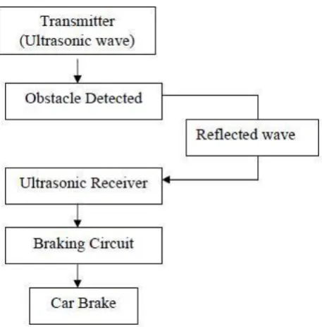
Fig -1: Flow Diagram of Intelligent Reverse Braking System
2.1 BRAKING CIRCUIT :
The processed signal will be send to the braking circuit. At the braking circuit, there is a controller that can process the signal and give the instruction to the output based on condition of the signal. For this project, controller that used is PIC 16F84A microcontroller (8-bit microcontroller). PIC 16F84A microcontroller use the high language and easy to do the programming. Above is shown about Flow Chart of Development of this project. Once, the title of this project Ultrasonic Car Braking System is selected. The identifying andunderstanding process was done. In this process, I found out all notes and information related to the project.
The process was divided into two main groups which are software and hardware development. For the software development, the controller that prefers is PIC16F84A microcontroller (8-bit microcontroller). Therefore all programming must suitable and match with this controller. The process of software development is continuously done until get the perfect resulted.
For the hardware development, the focus is to develop the circuit and board for PIC16F84A microcontroller. Besides, focus is to develop ultrasonic circuit to implement to this
project. After that, we must do the connection between ultrasonic sensor (transmitter & receiver), PIC16F84A microcontroller and lastly motor for the output.
The process of Integration Hardware and Software is very important because to interface the software and hardware is so hard. Although, the simulations will right output, it is not perfect for the real situation. The problem will exist after we try to interface both. So, doing analysis is compulsory to correct the software or hardware so that we can get the right result.
The steps required to read the distance and controlling the speed of a vehicle are:
1. Microcontroller makes the I/O line output. (By using the DDR x Register in AVR or TRIS x Register in PIC)
2. The I/O line is made low (this may be the default state of I/O pin)
3. Wait for 10uS
4. Make the I/O line high, 5. Wait for 15uS
6. Make the I/O line low 7. Wait for 20uS
8. Now make it input (by using the DDR x Register in the obstacle and come back to the module.
9. Module will keep it low. Wait when the pulse is low, as soon as that becomes high start the timer.
10. After this, wait till pulse is high and as soon as that becomes low copy the timer value and stop the timer.
2.2 ULTRASONIC TRANSMITTER:
Before transmit the ultrasonic wave, there is a part which is ultrasonic wave generator that function to generate ultrasonic wave. In that part, there is timing instruction means for generating an instruction signal for intermittently providing ultrasonic waves. This signal will send to an ultrasonic wave generator for generating ultrasonic waves based on the instruction signal from said timing instruction means (transform electrical energy into sound wave). After ultrasonic wave was produced, ultrasonic transmitter transmits the ultrasonic waves toward a road surface to find out the obstacle. The range that obstacle detected is depends on the range of ultrasonic sensors that used.
2.3 ULTRASONIC RECEIVER:
© 2018, IRJET | Impact Factor value: 6.171 | ISO 9001:2008 Certified Journal | Page 151 compared with reference signal to detect components in the
amplified signal due to obstacles on the road surface. The magnitude of the reference signal or the amplification factor of the amplifier is controlled to maintain a constant ratio between the average of the reference signal and the average of the amplified signal.
3. BLOCK DIAGRAM AND DESCRIPTION
Ultrasonic ranging and detecting devices make use of high frequency sound waves to detect the presence of an object and its range. An ultrasonic sensor typically utilizes a transducer that produces an electrical output pulse in response to the received ultrasonic energy.
Fig -2: Block Diagram of Intelligent Reverse Braking System
The above block diagram shows the main components intelligent reverse braking system. There are two types of power supply are required viz. electric supply for the operation of control unit and IR sensor, and the air power supply to operate the pneumatic brake. IR sensor consists of IR transmitter and IR receiver.[5] IR transmitter transmits ultrasonic waves continuously. When car gets too close to an obstacle, the ultrasonic waves reflect back which was then receive by the IR receiver. After receiving the reflected signal, it gives the impulse to the control unit. This control unit make ON the solenoid valve. These complete processes are electronic based which required electric supply.
[image:4.595.313.559.59.243.2]A continuous supply of air through air tank is supplied to solenoid valve. The flow control valve is used to control the flow of air which allows the air to flow in one direction only that is only in forward direction and block in reverse direction. When signal from control unit receives by solenoid valve, a supply of compressed air supplied to pneumatic single acting cylinder. Then the piston takes forward motion and consequently brake applied to the wheel. This stops the car and accident is avoided.
Fig-3: Circuit Diagram of the Intelligent Reverse Braking System
Generally, IR sensors are fitted at rear of the vehicle and solenoid valve is located at the front wheel.
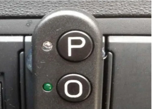
3.1 PARK MODE AND OVERRIDE BUTTUONS:
Intelligent reverse braking has override mode as well as park mode. In these two modes difference is the length of operation of the braking. In override mode the length of operation is about 1.6m, but for parking mode the length of operation is 40cm.
To allow the driver to park the vehicle or engage in tight reversing maneuvers, the system has a park mode. In this mode the sensors are reduced to 40cm. In addition, the system has an override button that overrides the braking system when held.
Fig -4: Park Mode and Override Buttons.
[image:4.595.43.282.258.437.2] [image:4.595.309.562.488.670.2]© 2018, IRJET | Impact Factor value: 6.171 | ISO 9001:2008 Certified Journal | Page 152
4. WORKING:
The whole system operates only when the car is moving in reverse direction. When vehicle is in the reverse gear, power supply is given to the sensor unit. Ultrasonic sensors generate high frequency sound waves and evaluate the echo which is received back by the sensor, measuring the time interval between sending the signal and receiving the echo to determine the distance to an object.
This reflected echo is received by the control circuit. If there is no obstacle in a path, the receiver circuit will not receive any signal and the whole signal remain as it is. Ultrasonic sensor receives the reflected echo and giving the control signal to the control circuit. The control circuit is used to activate the solenoid valve. If the solenoid valve is activated, the compressed air passes to the double acting pneumatic cylinder.
The compressed air activates the pneumatic cylinder and moves the piston road. If the piston moves forward, then the braking arrangement is activated. The braking arrangement will used to stop the wheels gradually or suddenly due to the piston movement.
For the blind spot reduction, shown in figure, two ultrasonic sensors are used which are attached at the side A pillars. LEDs are used to indicate driver during changing the lane or at the corner. When the sensor detects any vehicle in the range, it will send signal to the same IC circuit used in reverse braking system and indicate on the LED screen.
5. FUTURE SCOPE:
The comparator keeps comparing the values of signal strength and the braking takes place when required as shown. This proposed system can be easily implemented near different populated areas. The power of the proposed system lies in its flexibility and capability of development with little hardware changes such as changing the speed limits and speed control methods using the software of the base station in negligible amount of time. The proposed system is based on microcontroller technology for collecting data related to speed and transmitting it through a transceiver to a base station that analyzes the transmitted data and takes appropriate decisions related to speed limit and control requirements. This experience has encouraged us to learn more about upcoming trends and technologies and thereby adding our bumble knowledge and experience about the vast ocean of electronics. A revolutionary invention is made in the field of brakes. The Electromagnetic brakes are excellent replacement for conventional automobile brakes. The use of Electromagnetic brakes can be done for lighter vehicles also. With some modification, a regenerative braking system can be equipped with the Electromagnetic brakes. The Electromagnetic brakes are the future of automobile brakes. The intelligent braking system provides a total safety in the negligence of the driver inthe
emergency situation thus saving reduction in loss of precious human lives and properties. Thus there is no doubt that this system becomes the future braking system for the automobiles. In addition to the braking system, an additional module is developed for controlling the direction of the vehicle. The remote controller is developed using RF transmitter and receiver which is interfaced with microcontroller. The whole system works only while reversing the vehicle. When the sensor senses any obstacle behind the vehicle, it sends signal to the control unit (FPGA). FPGA which act as a controller logic is designed with the help of FSM, which will sense the object according to the digital input and action will be taken accordingly. For a future development of this project, the Logic Controller designed can be enhanced by applying more rules. By then, it can produce better response. The response should be better and can be applied to a real hardware model to observe the real response and yet can improve the system. The proposed system can be replaced by an ASIC in future.
CONCLUSIONS:
In the present work, a prototype of an ultrasonic distance measurement for stationary obstacle is obtained. And controlling the speed of vehicle accordingly to predetermined distance is shown. An ultrasonic sensor, cheaper and less demanding of hardware than other types of sensors presently used, such as the sensors based on computer vision or radar , is used to measure the distance between vehicle and the obstacle. The relative speed of the vehicle with respect to the obstacle is estimated using consecutive samples of the distance calculated. These two quantities are used by the control system to calculate the actions on both the accelerator and also the brake, thus to adjust the speed in order to maintain a safe distance to prevent accidents. As ultrasonic sensors can detect any kind of obstacle, this system can also prevent collision of the vehicle with pedestrians, or can at least reduce the injuries occurring.
REFERENCES
1]www.autotrader.com
http://www.autotrader.com/research/article/car- news/210852/new-automatic-parking-system-will-reach-volvo-models.jsp, October 12, 2014.
2]Bimba Manufacturing Company, Pneumatic Application and Reference Handbook, PP 5-12, 2012.
3] FESTO, “Solenoid/pneumatic valves, ISO 15407-1”, PP 20-26, 2013.
4] G.V. Sairam, B. Suresh, CH. Sai Hemanth and K. Krishna Sai, “Intelligent Mechatronics Braking System”, PP 100-102, 2013