FINITE ELEMENT ANALYSIS OF MID-DIAPHYSEAL TRANSVERSE
FRACTURE BASED ON CORTICAL BONE HETEROGENEITY
Nurul Najwa Mansor1, Ruslizam Daud1 Khairul Salleh Basaruddin1, Fauziah Mat1 and Yazid Bajuri2
1Fracture and Damage Mechanics, School of Mechatronic Engineering, Universiti Malaysia Perlis, Arau, Perlis, Malaysia
2UKM Medical Centre, Department Orthopaedics and Traumatology, Universiti Kebangsaan Malaysia, Kuala Lumpur, Malaysia
E-Mail: nurulnajwa@studentmail.unimap.edu.my
ABSTRACT
The failure of bone may cause from accumulation of micro cracks, and will affect the micro structure features. The composition in cortical bone can be in the composite structure which has variety in material properties and play a role to macroscopic fracture behavior of whole bone structure. The composition in bone can be demonstrated as heterogeneous material properties which considered as constituents of osteon, cement line, interstitial matrix and Haversian canal. It is hypothesize that linear stress interaction exist and growth to intensify the interaction between constituents. This paper presents a finite cortical bone model based on continuum mechanics theory to identify the linear elastic interaction between four constituents and evaluate its model based on the standard analytical model for brittle fracture. Finite element method is employed to calculate the interaction fracture parameter, stress intensity factor (SIF) and energy release rate for four anatomical positions in cortical bone which are posterior, anterior, medial and lateral are considered due to different variability of bone properties. The results demonstrates the highest value of SIFs at posterior cortex and found lowest at lateral cortex. It is identified that numerical data is in good agreement with analytical model for brittle fracture.
Keywords: diaphyseal fracture, heterogeneity, SIFs, finite element method.
INTRODUCTION
Biomechanical study demonstrates that the behavior of whole bone structure is depending to cortical bone [1]. Due to complex microarchitecture of cortical bone, it has significant effect in mechanical and fractured properties due to different loading modes and orientations. Bone failure may affect from arrangement of microstructure cortical bone such as porosity, mineralization, orientation, diameters and spacing of collagen fiber. Cortical bone’s mechanical property is not only effect by microstructure but also the direction of crack microstructure due to deformation of crack length and fracture behavior of cortical bone tissue by considering different loading modes (longitudinal and transverse crack) and orientations of four anatomical quadrant positions (posterior, anterior, medial and lateral).) The distinctions of anisotropy and variability of mechanical properties in four quadrants of bovine cortical bone under tension and compression using experimental procedure is studied by [2]. By experiment, [3] consider studying the elastic-plastic behavior in different directions, transverse and longitudinal axis and mechanical properties for 4 different cortices using the experimental procedures. More details, [2] studied the causes of bone failure in different crack direction, transverse, radial and longitudinal direction of crack in four cortices, posterior, anterior, medial and lateral by implementing the experimental and numerical data using J - integral parameter. Few finite element models were used to model and analyzed the fracture behavior of microstructural cortical bone tissue. In example, [4] used a cohesive finite element modeling to investigate the mechanism that effect crack penetration into osteons or deflection into cement line [5] modeled the Haversian cortical bone using linear elastic fracture theory in order to investigate the interaction of microcracks and osteon. [6] introduced
multiple scale method for modeling multiple crack growth in cortical bone under tensile loading by using extended finite element (FE) method, X-FEM Matlab/Gmsh for discretized the final geometry. In another attempt, [7] study the influence of porosity, osteon bone, and orientation of Haversian system on macroscopic elastic moduli and Poisson’s ratio of cortical bone. The osteon in cortical bone can be promoted or retarder is dependent on ratio elastic modulus of osteon towards the interstitial matrix studied by [1]. This study aims to investigate the effect of cement line, interstitial matrix and osteon with difference material properties in cortical bone structure that caused transversial fracture.
MATERIAL AND METHOD
Figure-1. Middle diaphysis loading and boundary condition.
Table-1 summarizes the properties used in this numerical simulation. The material properties of this micro-structural and heterogeneous property which regard to bone axis and transverse crack are obtained from experimental data [3].
Table-1. Young’s modulus and poisson ratio for
transverse fracture of four cortices.
Cortices Interstitial matrix
(GPa)
Poisson ratio, v
Posterior = 10.20 0.153
Anterior = 13.20 0.153
Medial = 14.122 0.153
Lateral = 11.18 0.153
Table-2. Young’s modulus and poisson ratio for 4-phase
constituents’ model.
Cortical bone
segment modulus (Young’s GPa) Poisson ratio, v
Osteon 9.13 0.17
Cement line 6.85 0.49
Interstitial matrix 14.122 0.153
Haversian canal - -
In meshing scheme arrangement, the global mesh is optimized and set to 0.02 mm while 0.01 near the crack tip, as shown in Figure-2(a). Meshing scheme of 8-node quadrilateral element is employed for all the global and local elements. Singularity element surround the crack tip is based on Barsoum singularity element, set to local mesh. Figure-2(b) shows the schematic Barsoum singularity element used in the stress intensity factor (SIF) formulation for Mode I and Mode II fracture. SIFs for
3 5 2 4
(
,
,
,
)
(
)
2
4(
)
3(1
)(1
)
2
IFE IA IP IM IL
y
K
K
K
K
K
v
v
E
v
v
l
(1)
3 5 2 4
(
,
,
,
)
(
)
2
4(
)
3(1
)(1
)
2
IIFE IIA IIP IIM IIL
x
K
K
K
K
K
u
u
E
u
u
l
(2)
where,
E E E E
(
A,
P,
M,
E
L)
is Young Modulus for posterior, anterior, medial and lateral cortices for transverse fracture.
3 4
v
for plain stress and3 4
1
v
v
for plain strain,l l l
( , )
y x is length of element,v
andu
are displacements in a local Cartesian coordinate system and
is Poisson’s ratio.1
11
X
Y
Z
AUG 23 2016
12:10:17 DISPLACEMENT
STEP=1 SUB =1 TIME=1 DMX =.003955
Figure-2. (a) Local and global meshing scheme and (b)
crack tip singularity element.
Based on the LEFM assumption of bone fragility, the brittle transverse isotropic heterogeneous materials, Equation. (1) can be expressed as Stress intensity factor (SIF) for brittle transverse isotropic heterogeneous materials, Equation. (1) can be expressed:
( / )
IFE FE yy
RESULT AND DISCUSSIONS
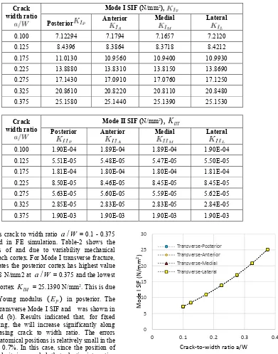
Table-3. SIFs for Mode I and Mode II for four cortices in transverse crack.
Crack width ratio
Mode I SIF (N/mm2),
Posterior Anterior Medial Lateral
0.100 7.12294 7.1794 7.1657 7.2120
0.125 8.4396 8.3864 8.3718 8.4212
0.175 11.0130 10.9560 10.9400 10.9930
0.225 13.8880 13.8310 13.8150 13.8690
0.275 17.1430 17.0910 17.0760 17.1250
0.325 20.8610 20.8220 20.8110 20.8480
0.375 25.1580 25.1440 25.1390 25.1530
Crack width ratio
Mode II SIF (N/mm2),
IIT
K
Posterior Anterior Medial Lateral
0.100 1.90E-04 1.89E-04 1.89E-04 1.90E-04
0.125 5.51E-05 5.48E-05 5.47E-05 5.50E-05
0.175 1.81E-04 1.80E-04 1.80E-04 1.81E-04
0.225 8.50E-05 8.46E-05 8.45E-05 8.45E-05
0.275 5.63E-05 5.60E-05 5.59E-05 5.62E-05
0.325 2.85E-05 2.83E-05 2.83E-05 2.84E-05
0.375 1.90E-03 1.90E-03 1.90E-03 1.90E-03
Various crack to width ratio
a W
/
= 0.1 - 0.375 were considered in FE simulation. Table-2 shows the different values of and due to variability mechanical properties for each cortex. For Mode I transverse fracture, the result indicates the posterior cortex has highest value ofK
IP= 25.158 N/mm2 ata W
/
= 0.375 and the lowest for the medial cortexK
IM = 25.1390 N/mm2. This is dueto the lowest Young modulus
(
E
P)
in posterior. The relationship of transverse Mode I SIF and was shown in Figure 3(a) and (b). Results indicated that, for fixed transverse loading, the will increase significantly along with the increasing crack to width ratio. The errors between four anatomical positions is relatively small in the range of 0.02 - 0.7%. In this case, since the position of osteons is fixed, it is revealed that elastic interaction parameters determined by Equation. (1-3) is reliable, and the effect of is more significant as increased near to the cement line.Figure-3(a). Stress intensity factor for transverse crack in
all cortices for mode I. 0
5 10 15 20 25 30
0 0.1 0.2 0.3 0.4
Mod
e
I
SI
F
(N/mm
2)
Crack‐to‐width ratio a/W
[image:3.612.136.511.127.606.2]Figure-3(b). Stress intensity factor for transverse crack in all cortices for mode II.
Table-3 also shows the results of Mode II SIF relative to = 0.1 - 0.375. Figure-3(b) shows the relationship trend as increased. It can be seen, the Mode II seems to have no significant effect to the interaction between cracks and osteons, hence can be
neglected. However, while the transition from 0.325 to 0.375, seems to fluctuated rapidly peak at 1.90E-03 N/mm2 for all cortices. This trend shows significant
elastic interaction as the crack tip near to the cement line of osteons.
Table-4. SIFs between numerical and analytical data.
Crack
width ratio Mode I SIF (N/mm
2) from empirical formula
Tada (1973) (1964,1966) Gross & Brown Brown & Srawley (1964)
0.100 7.1040 7.1808 8.5400
0.125 8.1627 8.2558 9.8481
0.175 10.3278 10.4400 12.5464
0.225 12.7130 12.8252 15.4998
0.275 15.4689 15.5624 18.8541
0.325 18.7462 18.8045 22.7867
0.375 22.7248 22.7344 27.5445
For results validation, the results were compared with Tada (1973) , Gross and Brown (1966) and Brown and Srawley (1964, 1966) . Table 4 shows the variation of SIFs subjected to transverse loading. Tada (1973) and Gross and Brown (1966) formulation show a good agreement to present , as shown in Figure-4.
‐5.00E‐04 0.00E+00 5.00E‐04 1.00E‐03 1.50E‐03 2.00E‐03 2.50E‐03
0.05 0.15 0.25 0.35 0.45
Mode
II
SI
F
(N/m
m)
Crack‐to‐width ratio a/W
Transverse‐Posterior Transverse‐Anterior
Transverse‐Medial
Transverse‐Lateral
10 15 20 25 30
Mode
I
SIF
(N
/mm)
CONCLUSIONS
Four different cortices of finite diaphyseal fracture models in human cortical femur bone were developed to study the effectiveness of SIFs and strain energy release rate parameters subjected to tensile loading. In the present study, the transverse isotropic crack is assumed with heterogeneous properties (osteon, cement line and interstitial matrix) considering four cortices; posterior, anterior, medial and lateral. Based on the numerical results, this paper can be concluding that the values of and are different for each cortex due to effect of different mechanical properties of Young modulus, E. For comparison between numerical model and empirical formula, can be concluded that Tada (1973) and Gross and Brown (1966) can be as reference of brittle fracture.
REFERENCES
[1] X.E. Guo., L.C Liang. and S.A. Goldstein, “Micromechanics of Osteonal Cortical Bone Fracture,” Biomechanical Engineering, Vol. 20, pp. 112-117, 1998.
[2] S., Li A. Abdel-Wahab. and V. V. Silbeschmidt, “Analysis of Fracture Processes in Cortical Bone Tissue,” Engineering Fracture Mechanics. Vol. 110, pp. 448-458, 2013.
[3] A.A. Abdel-Wahab, K. Alam and V. Silberschmidt,” Analysis of Anisotropic Viscoelastoplastic Properties Cortical Bone Tissues,” Mechanical Behaviour of Biomedical Matetrials. Vol. 4, pp. 807-820, 2011.
[4] S. Mischinki and A. Ural, “Finite Element Modeling of Microcrack Growth in Cortical Bone,” Applied Mechanics. Vol. 78, pp. 1-9, 2011.
[5] A.R. Najafi, M.R., Arshi, M.R. Eslami, S. Fariborz and M. Moeinzadeh, “Haversian Cortical Bone Model with Many Radial Microcracks: An Analytic Solution,” Medical Engineering & Physics. Vol. 29, pp. 708-717, 2007.
[6] E.Budyn and T. Hoc,” Multiple Scale Modelling for Cortical One Fracture in Tension using X-FEM,” REMN, Vol. 16, pp. 215-238, 2007.
[7] H. A. Hogan, “Micromechanics Modeling of Haversian Cortical Bone Properties,” Biomechanics. Vol. 25, pp. 549-556, 1992.
[8] N.K. Sharma, R.Pal, K. Seghal and R.K. Pandey, “Application of Elastic-Plastic Fracture Mechanics to Determine the Locational Variation in Fracture
Properties of Cortical Bone,” Materials Performance and Characterization. Vol. 3, pp. 429-447, 2014.