International Journal of Emerging Technology and Advanced Engineering
Website: www.ijetae.com (ISSN 2250-2459, ISO 9001:2008 Certified Journal, Volume 6, Issue 4, April 2016)
75
XYZ Axis Crane
Dangal Kishor
1, Gaikwad Prashant
2, Gaikwad Shantaram
3, Gaikwad Yogesh B.
4, Prof. Aher H.R.
5,
Prof. Bhane A.B.
61,2,3,4
Students, 5,6Assistant Prof. of SND College of Engineering & Research Centre, Department of Mechanical Engineering, Yeola, Nashik, India
Abstract-- The aim of the project is to design, develop and implement Advance xyz axis industrial crane which helps to achieve or cover the maximum working area in industry. The conventional cranes used in industry for material handling is not safe due to complex balancing of material and the area covered by crane is not much. The control of the crane is important parameter so, it does not achieve by conventional industrial crane and cost required material handling gets increased. These factors motivate the development of an industrial crane.
Keywords-- construction, design, lead screw, safety, spray painting,.
I. INTRODUCTION
In our daily life, the strength of human is very limited and cause difficulties in handling with huge materials. Cranes are essential machinery on modern world and are used to perform tasks which require the movement of heavy loads in different fields of industry such as construction, transportation or in manufacturing for the assembly of heavy components. In order to utilize of manpower, heavy machinery is needed to make the work become easier and less time to complete the task. Cranes are not merely the largest, the most conspicuous, and the most representative equipment of construction sites but also, at various stages of the project, a real “bottleneck” that slows the construction process. Although the crane can be found standing idle in many instances, yet once it is involved in a particular task, it becomes an indispensable link in the activity chain, forcing at least two crews (during loading and unloading) to wait for the service. Nowadays, the improvement of technology made 3-Crane System as one of the suitable heavy machinery transporter to be used in the industries. The purpose of 3-axis crane is to transfer variety of material from one location to another location in order to load and unload of huge materials where heavy loads must be moved with extraordinary precision. The main aim of the project is the design and production of a 3-Axis crane having arm motion in the vertical as well as horizontal plane with 180 degree rotation.
These cranes provide an efficient, low cost alternative to other material handling equipments. Strong, robust, sturdy and built to very standard, these cranes are maneuverable in loading, unloading and shifting of heavy loads.
As analysed in other publications [1,2] it is feasible to automate crane navigation in order to achieve better economy, higher productivity and safe operation. The limited degrees of freedom for the crane arm make the complicated material handling method in industry. These factors motivate the development of an xyz axis crane[1]. When the advance system implement in industry thenthe cost required for material handling gets reduced and the safety for workers get improve [2].
II. LITERATURE REVIEW
For a minimizing the complexity and also the cost, the support system selection must have simple configuration, a minimum work area and requires less complex control system [3].
Development of the jib of crane forms the most inventory part of xyz axis crane. A suitable support system must be selected from various alternatives for avoiding failure of crane jib by various kinematics mechanism and by motion tracking. The path traversed by the hooke of the crane is distorted and needs improvements in motion and control of hooke [3].
Below of the previous crane in which the motion is restricted. In that the motion of crane arm is vertical up and down, rotary motion along the vertical axis.
International Journal of Emerging Technology and Advanced Engineering
Website: www.ijetae.com (ISSN 2250-2459, ISO 9001:2008 Certified Journal, Volume 6, Issue 4, April 2016)
76
In this type of crane the support is fixed beam type the movement of horizontal arm is only up and down and the rotory moment along axis of the beam.Fig.2 actual setup of xyz axis crane
The actual setup works with the help two energy sources electricity and pneumatic system. The pneumatic system used for operating the pneumatic cylinder which is mounted on the arm of the crane to achieve the task of project. The other motion of crane occurs due to electric energy source the two motors are mounted on the crane for vertical up and down and rotary motion of arm. The Floor Crane itself is designed for Ergonomical operation as it reduces manual effort,bending & is convenient to use .As it requires less force to operat & thus save energy It is designed as per safety & there are no sharp edges to avoid injury.It is Light weight, Noise free additionally good quality surface treatment & paint is used
III. WORK STUDY
The basic procedure is a complete fundamental to the whole work study. The examination of the process occurs due to the following sequence of phase in that order.
1)Select the work which is to be study. 2)Record all the data related to the problem. 3)Examine the problem critically but impartially. 4)Develop the model, by economic and effective
method.
5)Define the new model so that it can be always being identified.
6)Install that new method as standard practice. 7)Maintain that standard practice by regular routine
maintenance.
In many large construction projects and in industry, the materials delivered by different suppliers are first checked in and stored in an on-site warehouse prior to being distributed between different work areas. The distribution process generally involves lifting equipment such as a tower crane, a crawler crane, or a gantry (bridge) crane, fixed beam crane, automobile crane. As far as the material distribution is concerned, the crane is the most important parameter of transport which implies that delays in crane operations can potentially cause bottlenecks in project schedule in the industry. In order to meet the demand of the working crew and avoid the bottlenecks in industry, the crane’s hook should be repeatedly traversing between material storage areas (loading sites) to crews’ locations, where material is unloaded. Since this process is iterative by nature, effective planning and controlling of the crane
movements can directly improve the project
performance.
A limited amount of research was aimed at improving the planning and control stage of the crane work cycle. For example, Leung and Tam (1999) developed a model to predict the hoisting time of tower cranes. The model examined the contribution of different variables in addition to the hoisting height. They used multiple regression models to identify factors affecting the hoisting times based on their importance. This enabled planners to manipulate the variables in order to shorten the hoisting time. Tam et al. (2002) explored possible improvement in hoisting time prediction by using nonlinear neural network models. Zhang et al. (2007) used ultra wideband sensors to collect real time data for the purpose of crane path re-planning to avoid possible collisions in a industrial zone. Leung and Tam (2003) demonstrated the use of simulation to improve the
scheduling strategies and reviewing the floor
construction schedule. Navon (2005) described a method to collect data about indirect project parameters (e.g. location of workers) in order to automate the measuring
of project performance indicators (i.e. labor
International Journal of Emerging Technology and Advanced Engineering
Website: www.ijetae.com (ISSN 2250-2459, ISO 9001:2008 Certified Journal, Volume 6, Issue 4, April 2016)
77
In order for any crane planning operation, including those described above, to yield accurate and meaningful output, it is imperative that an adequate level of crane operational data collected from the field be used as an input. In the absence of a continuous stream of realistic input data, even the most sophisticated planning approaches may results in little added value. Hence, the presented research was motivated by the need for a methodology that uses data collected from physical crane motions at each degree-of-freedom (DOF) in order to calculate parameters that describe the events inside a crane work cycle. Such events mark the beginning and end of loading, lifting, transporting, and unloading activities that when put together in a chronological order, form a complete crane work cycle. To achieve this goal, real time operational data from a construction crane is collected and interpreted to predict the crane’s future performance and the effect of this performance on the overall project completion. This model can be used to predict the performance of the project as well as to select the best combination and arrangement of cranes on the jobsite to achieve the maximum possible efficiency.Preliminary research that the crane work cycle always starts at the loading area. In order to determine the position of the crane’s hook, the angular velocity of the heading angle is compared to a predefined threshold. If the angular velocity of the jib is smaller than this threshold, it is concluded that the crane jib is jittering (due to factors such as payload inertia or wind) inside the loading area. As soon as the angular velocity maintains a steady change, and the transmitted heading angles show a movement away from the loading area, the crane is involved in an instant of transporting activity. Once the jib’s heading angle reaches a steady value and the angular velocity decreases to less than the predefined threshold, it is conceived that the hook is inside the unloading area. Finally, as soon as the crane jib starts moving back towards the loading area, the heading angle values transmitted by the orientation tracker show a steady change towards the initial value corresponding to the loading area. This process repeats until the crane operation ends. Table 3 provides a sample pool of heading angle data collected from a model tower crane using the PNI data logger software. Data logger uses ticks (1/60 of a second) to measure time. The observation was taken from a crane jib moving repetitively between loading and unloading areas.
Typically, project decision-makers use their expert judgment or data from previous projects to estimate activity durations. It is conceivable that the ability of a simulation model to properly predict the performance of a project highly depends on the reliability and preciseness of the model parameters.
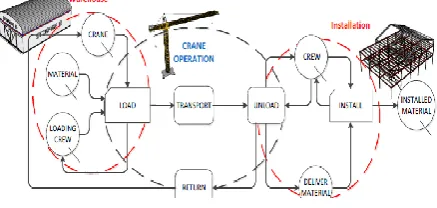
Without a comprehensive understanding of project components and logic, it is almost impossible to develop a realistic simulation model of that project. Figure 3 illustrates a discrete event simulation (DES) model
corresponding to a warehouse crane operation. As shown
in this Figure, the model mainly consists of three main zones: storage (i.e. warehouse), transport (i.e. crane), and final installation. In addition to a crane, the Load activity requires that a loading crew and material be available.
[image:3.595.320.539.306.410.2]Also, the Unload activity requires that a crew is available to unload and install the material. In order to avoid piled up material in the installation area, it is assumed that the material is unloaded from the crane by the same crew who installs the material.
Fig.3. simulation model of crane operation [5]
As a result, as long as the crew is busy installing, the crane has to wait (in an idle position) to be unloaded. The operation continues until all material is moved from an initial storage area (e.g. onsite warehouse) to the location of final installation. In order for this simulation model to be a realistic representation of the entire operations, it is necessary that both crew and crane activity times be collected, analyzed, and incorporated into the simulation model.
The DES model in Figure 3 consists of four crane-related activities: Load, Transport, Unload, and Return. In order to have a realistic simulation model, the parameters for these activities (as well as other activities inside the DES model) need to be carefully calculated. One such parameter is activity duration.
Table 1.
Description of major crane activity
[image:3.595.315.548.622.703.2]International Journal of Emerging Technology and Advanced Engineering
Website: www.ijetae.com (ISSN 2250-2459, ISO 9001:2008 Certified Journal, Volume 6, Issue 4, April 2016)
[image:4.595.49.283.181.767.2]78
Using the developed data analysis methodology, probabilistic distributions shown in Figure 4 can be assigned to describe the durations of crane activities in the DES model.Fig. 4.Probabilistic distributions describing different crane activities [5]
Manufacturing processes
Manufacturing process is a collection of technologies and methods used to define how products are to be manufactured.
Manufacturing of crane involves various process such as:
Fabrication
Manufacturing process in which an item is made (fabricated) from raw or semi-finished materials instead of being assembled from ready-made components or parts. it involves cutting ,bending and assembly process.
Fabrication involves following process:
Cutting process, forming process, machining, welding, assembly, surface finishing, testing and painting.
By applying above process the final completion of work is carried out.
The working area covered by this crane is depends on the pneumatic cylinder stoke length, as the stroke length increase the working area covered by crane gets increased.
Space performance:
In this the following parameter are consider
Accuracy: checking the absolute accuracy of arriving, from any arbitrary point within the crane’s work envelope, at a prerecorded point, marked very precisely when being recorded (“Goto”). The accuracy was checked separately for each joint, and with different loads within the crane’s capacity, in order to discover any slippage or systematic error in it.
International Journal of Emerging Technology and Advanced Engineering
Website: www.ijetae.com (ISSN 2250-2459, ISO 9001:2008 Certified Journal, Volume 6, Issue 4, April 2016)
79
Repeatability is measured by the scatter of the results in multiple cycles, irrespective of their absolute location. It should be measured under similar conditions and with the same load.Path navigation: checking the extent to which the hook in fact follows the safe path. It discovers whether additional “through-points” are necessary to secure a collision-free travel of crane. These tests resulted in some generalized lessons with regard to important rules for the insertion of critical through-points intended to avoid obstacles.
For time saving during material handling long distance navigation test may carried out from the loading zone to the unloading zone and back, without high precision. The durations of conventional crane by a skilled operator through predefined “safe corridors” represented by a number of paths quite typical of construction sites, were compared with the time required by xyz axis crane through the same paths performed by the same operator.
IV. CONCLUSION AND FUTURE RESEARCH
From the above research paper we studied that xyz axis crane can be not only aimed at improving the degree of freedom of crane, but also cover a large circular area & reduce human effort, improve safety and efficient. The purpose is to reduce maintenance required for crane. It can used for load varying applications, Higher range of reach can be achieved for lower load, i.e for ½ ton to 1 ton. The hydraulic cranes used in the industry are efficient but they only have the ability to lift the load and put it down at some other position. But this type of crane works in varying area from fixed support.
In future research we can use microcontroller to actuate the crane and increase the stability of the crane hooke instead of electric motors we can implement pneumatic rotay type actuators and DCv can operate with the help of controller. As regular crane maintenance, random break-downs, and wind effect that may adversely
affect crane operations, effective planning and
controlling of the crane movements can directly improve the performance of crane. In future tower crane can be equipped with a 3D orientation sensor to capture the angular movement of the jib as it repetitively traverses between a material storage area and a crew location.
REFERENCES
[1] Rosenfeld, Y. and Berkovitz, S., Automation of existing tower cranes -- economic and safety examination, Proc.6th Int. Symp. on Automation and Robotics in Construction,San Francisco, June 6-8, 1989.
[2] Rosenfeld, Y. and Berkovitz, S., Automation of construction cranes, Technical Report #017-438, National Building Research Institute, Technion - I.I.T., Haifa, 1990.
[3] Asmita Jadhav, Mayank Kachroo, Mahesh Hegde, ruchita Mantri, “Optimization in Design of Rotating Hydraulic Crane”,
International Journal of Engineering and Advanced Technology (IJEAT) ISSN: 2249-8958, Vol. 3, Dec 2013 pp. 76-82.
[4] Huang Li-Jenga* & Syu Hong-Jieb, “Seismic Response Analysis Of Tower Crane Using SAP200”, Procedia Engineering 79(2014), pp. 513-522.
![Fig. 4.Probabilistic distributions describing different crane activities [5]](https://thumb-us.123doks.com/thumbv2/123dok_us/8692512.877493/4.595.49.283.181.767/fig-probabilistic-distributions-describing-different-crane-activities.webp)
