International Journal of Emerging Technology and Advanced Engineering
Website: www.ijetae.com (ISSN 2250-2459,ISO 9001:2008 Certified Journal, Volume 5, Issue 6, June 2015)
402
Intentional Software Product Line using Model Driven
Engineering
Sami Ouali
1, Naoufel Kraïem
2, Henda Ben Ghezala
31,2,3
RIADI Lab, ENSI, Compus of Manouba, Manouba, Tunisia
Abstract— Software product lines are recognized as a successful approach to reuse in many domains (cars, printers, phones…) and especially in software development. Software Product Line engineering can be benefic to companies throw a
significant improvements in time-to-market, cost,
productivity, and system quality. The main purpose of Software product lines is to explore commonalities and variabilities of a software family throw the use of a set of methods and techniques for the construction of customized software products. This paper presents an intentional process for the construction of software product lines using Model Driven techniques. This process combines the use of many visual techniques for the modeling of product lines, especially features diagrams and Model Driven techniques. The passage between visual techniques is done using transformation rules. We present in this paper some of these rules. We propose also a tool which supports our approach and can helps users in the design and the construction of Software product lines.
Keywords—Intentional approach, Model Driven, Software product line, variability, tool support, MAP, features diagrams.
I. INTRODUCTION
The study of software requirements is an essential step in the life cycle of any software. It consists on the study of functionalities and qualities which should be taken into account during design and be present or characterize the
obtained software. The purpose of goal-oriented
requirements engineering is to study the stakeholder goals and to refine them into a space of alternative functionalities. With the large number of companies’ products, the improvement of time-to-market, cost and productivity becomes the factor of success of any of them. The concept of software product-lines have emerged from this need. It is considered as a central paradigm for systematic, large scale software reuse.
Software product lines are recognized as a successful approach to reuse in software development [1, 2]. Its purpose is to reduce production costs. This results are obtained throw the sharing of a reference architecture and concepts of the products. This approach allows products to be different with respect of particular characteristics and constraints in order to cover different markets.
Software Product Line engineering is the production process in product lines and its purpose is to maximize the commonalities of the product family and to minimize the cost of variations [28]. It exploits the commonalities between software products, but also to preserve the ability to vary the functionality between these products. The variation between products refer to the concept of variability which can be defined as the ability of a system, an asset, or a development environment to support the production of a set of artifacts that differ from each other in a preplanned fashion [4]. Variations in a product line context must be anticipated to obtain wished results.
Software product line engineering can be combined with another approach which is model-driven engineering. These two approaches are recent trends that have been drawing increased attention from the software development community due to their capability to enhance reuse. Model-driven engineering (MDE) aims to capture every important aspect of a software through the appropriate models, but also to allow transformation between these models. Model transformations allow to SPL engineers to more or less automatically go from model to another one, i.e. it opens the possibility to more or less automatically derive software from its models.
This paper presents an intentional process for the construction of software product lines using Model Driven techniques. In this process we focus on two levels of
engineering: Domain Engineering and Application
International Journal of Emerging Technology and Advanced Engineering
Website: www.ijetae.com (ISSN 2250-2459,ISO 9001:2008 Certified Journal, Volume 5, Issue 6, June 2015)
403
Eclipse Plugin provide many extensions points which can reduce our development effort.
This paper is organized as follows. In section 2 we present our comparison framework. In section 3 we present the purpose of the use of Model Driven techniques in software product lines context. We summarize a meta-model for intention and feature meta-modeling in software product lines context. Our Model Driven Software Product Line Process and its transformation rules are described in this section. This process is supported by a tool which is presented in the fourth section. The section 5 presents some related work. The section 6 concludes this work with our contribution and research perspectives.
II. COMPARISON FRAMEWORK
We try throwing our research to acquire and to improve our understanding of the field of software product line. We aim also to identify potential contributions to SPL engineering methods using the approach of comparison framework. Defining a comparison framework has proved its effectiveness in improving the understanding of various engineering disciplines in literature. This approach was used in [5] to understand and classify approaches based on scenarios in the field of requirements engineering and also used in the field of information systems by [29].
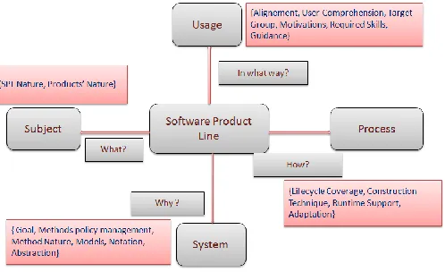
[image:2.612.330.579.135.287.2]We have elaborated a framework to compare different approaches for the construction of SPL. This framework is presented in [12] and evolved throwing this paper. The idea is to consider a central concept on four different points of view. In our context this central concept is software product line (SPL). Therefore, it can be helpful for the better understanding of the field of SPL engineering. To elaborate our comparison framework, we proceed by an analysis of issues that are crucial for the amelioration of SPL development method. As a result, our framework contains 18 facets organized into four views as presented in Figure 1.
Fig. 1. Software Product Line Comparison framework.
Each view allows us to capture a particular aspect of SPL engineering an. We try throwing our comparison framework to capture knowledge about the subject, the process of SPL construction methods, the use of construction methods and the system specifications. This knowledge is captured throwing the four views well known as worlds: usage world, subject world, system world and
process world.
Each view is characterized by a set of facets that facilitate understanding and classification of different aspects of SPL engineering. The facets are defined using attributes which are described by a set of value for measuring and positioning the observed aspect.
The usage world describes how systems are used to do
International Journal of Emerging Technology and Advanced Engineering
Website: www.ijetae.com (ISSN 2250-2459,ISO 9001:2008 Certified Journal, Volume 5, Issue 6, June 2015)
404
The subject world can be considered as a description of
the real world domain and the characteristics of the proposed system to meet both of these worlds. The proposed system should respect the domain-requirements imposed by the subject world. This view is characterized by the software product line’s nature and the resultant products’ nature.
The system world can be considered as a representation
of the system specifications using the requirements established in the usage world and the subject world. This view is characterized by a set of facets which allows us to take into consideration the goal of the methods, their policy management and their nature, also the used models and notation and finally the level of abstraction.
The process world represents the manner to obtain
proposed system. This view can be characterized by the lifecycle coverage, the used construction technique, the runtime support and the adaptation possibilities.
III. MODEL DRIVEN ENGINEERING FOR SOFTWARE PRODUCT LINE
Many approaches try to enhance the reuse of existing artifacts such the Model Driven Engineering and the Software Product Line Engineering. These engineering approaches have proven their efficiency in reuse field throwing the use of many techniques. In Software Product Line, the management of variability is the key of reuse as presented by Van Gurp [3]. In Model Driven engineering the focus concerns the capture of the different software aspects throwing the use of the appropriate models. These models can be reused in the associated step of software lifecycle. Models have the capacity to capture the intentions of the stakeholders and future users in more directly way. Models can be used also to automate some steps such the analysis and can offer the possibility to generate code.
We try throwing our approach to combine Software Product Line Engineering and Model Driven Engineering. This combination can be benefic for the improvement of reuse. The proposal of such approach can allow us to construct a software product line in a higher abstraction level. In fact Models are considered as a vision in a high abstraction level. In our approach we use a variety of variability models.
These models are used during the Software Product Line processes and offer a various possibilities for the production of artifacts, such as components, test cases, services, source code... Model Driven Engineering is used for the construction of Software Product Line throwing the proposal of a configurable model or a set of transformations between the used variability models.
The rest of this section presents our Model Driven Software Product Line Process where different notations are used such as MAP model and features model. These notations are used to define a meta-model which can be benefic to make the mapping between models easier. We present also some rules and patterns for mapping between the different used models such as MAP, features and classes’ model. These rules are extended to capture implementation models such as component model or service description.
A. Model Driven Software Product Line Process
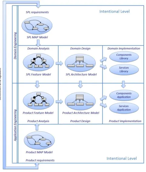
Our Model Driven Software Product Line Process tries to cover domain engineering and application engineering which are the main steps of Software Product Line lifecycle. In our process we try not only to coverage these steps but also to consider a new level which is the intentional one. We identify this layer to represent stakeholders’ intentions. This layer is used in both of domain engineering and application engineering. We try throwing this layer to model the stakeholders’ intentions for the software product line and for a particular product to construct in application engineering. The purpose is to propose an intentional process for software product line construction using the Model Driven approach for the passage between the proposed models. We present our process in Fig. 2 concerning domain engineering, application engineering, and the new intentional level. The domain engineering and the application engineering are the main steps of SPL lifecycle. They are related together.
International Journal of Emerging Technology and Advanced Engineering
Website: www.ijetae.com (ISSN 2250-2459,ISO 9001:2008 Certified Journal, Volume 5, Issue 6, June 2015)
405
We proceed in our process to determine features and their composition according to the Intentional Software Product line Meta model proposed in [24]. After that we propose to obtain classes diagrams from features models. This design view allows us to obtain a component architecture or service architecture throw components or services repository. This phase is simplistic for this moment. The component architecture view is done by creating an interface type and a component. The interfaces contain the signature of operations. The generated component implements required and provided interfaces. The service architecture view is done by the generation of services from design view.
[image:4.612.53.294.371.655.2]The application engineering process involves products derivation from the composition of existing artifacts created in the domain engineering process. In our case from existing components or services present in the components repository or services repository. It exploits the variability of the product line which allows the satisfaction of users needs.
Fig. 2. Approach for Software Product Line Construction
We integrate the new intentional layer in both of the two processes. During Domain engineering, it’s used to identify the intentions of SPL users.
During application engineering, we focus more on particular product intentions using the results of Domain engineering intentional layer. When we found a new intentions or strategies, we try to review the initial intentional model of the product line.
B. Variability Models
We need throw our process to model the variability in different levels of abstraction and during domain engineering and application engineering steps. To concretize this need in our process, we use a non exhaustive set of variability techniques and models. The reasons of our choice are based on the proven efficiency of these techniques in the expression of variability in different level of abstraction. We present in the next subsections these techniques.
1) MAP Model: A map is a process model expressed in
a goal driven perspective based on a non-deterministic of intentions and strategies [25]. MAP is considered as Intention-oriented process modeling which follows the human intention of achieving a goal which drives the process [12]. A map is composed of several sections, intentions and strategies. An intention is a goal [6] that expresses the expected state to reach and is represented as node of the graph. Strategies represent the manner or means to achieve intentions. The strategy is driven the flow from the source to the target intention which is the reason of directed nature of the graph. Map section can be refined as a more detailed map which allows abstraction reduction throwing the addition of more details on how a section can be reached. We use Map Model to represent variability in an intentional level where the variability is presented using the different strategies to reach an intention. This use has impact on both domain engineering and application engineering.
2) Feature Model: Feature modeling is a domain
International Journal of Emerging Technology and Advanced Engineering
Website: www.ijetae.com (ISSN 2250-2459,ISO 9001:2008 Certified Journal, Volume 5, Issue 6, June 2015)
406
These rules refer to some restrictions in features combinations such as the Requires-constraint and the Excludes-constraint between two features.
3) OVM Model: Orthogonal Variability Model (OVM)
[30] is used to document and to express variability on Software Product Line. The main concepts of OVM are Variation Point (VP), Variant (V) and Dependency. In an OVM model, we found only the variable item (VP) and their possible instances (V) without the common parts of SPL. Like in feature model, we can model the optional or mandatory property of both VPs and Vs. The Vs of the same VP are grouped in an alternative choice with a cardinality notation [min..max] to determine how many Vs may be chosen. The dependencies are constraints between nodes (mutex or require) which can be applied to both VPs and Vs.
C. Proposed Meta-Model
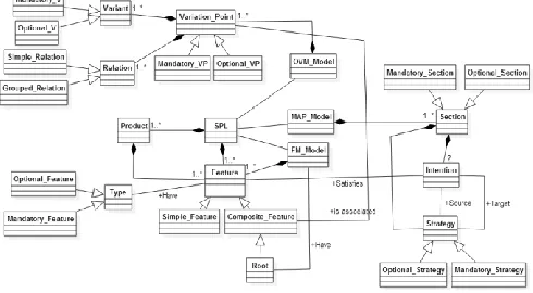
This section describes a meta-model synthesizing the different interesting points such as software product line, intention, features... We try throwing this meta-model to capture these concepts and to make easier the transformation steps between the different models and steps of the domain engineering and the application engineering. It will be useful for the definition of transformation rules to facilitate the integration into UML models and to use it in our Model Driven approach.
A software product line contains a set of products and is characterized by a set of features. A product is composed also of features. These features must check some constraints throw the conflict and require relationships. The product line is modeled by the use of many modeling techniques in different level of abstraction such MAP model, features model, OVM model for variability documentation and classes’ model for architecture modeling.
A MAP is composed of two or more sections and a section can be refined by a map [5]. Each section is composed of two intentions and one strategy. We make modifications on the original Meta-model by adding two types of section which are ―Optional_Section‖ and ―Mandatory_Section‖ and two types of strategies which are ―Optional_Strategy‖ and ―Mandatory_Strategy‖. These new classes allow us the definition of optional parts and mandatory parts on our intentional process. We add some OCL constraints to mention that an ―Optional_Section‖ is formed by an ―Optional_Strategy‖ and similarly for a ―Mandatory_Section‖.
[image:5.612.325.570.261.396.2]The feature Model is composed of a set of features. These features can be simple or composite. The composite feature is formed by a set of features. The root feature is a composite one and must be a singleton. The features can be optional or mandatory. A feature is proposed to satisfy an intention. To document the variability we use OVM model composed of variation points which are associated with some of the composite features and can be optional or mandatory. Variants and relations represent a part of one variation point.
Fig. 3. Meta model presenting different concepts
D. Patterns to automate transformations
We propose a model driven process for software product line construction. In this product line development process we focus on domain engineering and application engineering. Intentions and features models are used to lead to architecture model. Our architectural model deals only with structural view which is UML class diagram. We define some rules to try to automate derivation between requirement models to UML class diagram. We recognize that the transformations that we propose can’t be univocal. It is a try on to facilitate the task of SPL designer in the construction of software product line and a particular product.
We differentiate three kinds of transformations: SPL requirements are mapped to feature models, features are mapped into variation points and variants and the structural information of the feature models is mapped to class diagrams. We define some rules of transformations between these notations.
International Journal of Emerging Technology and Advanced Engineering
Website: www.ijetae.com (ISSN 2250-2459,ISO 9001:2008 Certified Journal, Volume 5, Issue 6, June 2015)
407
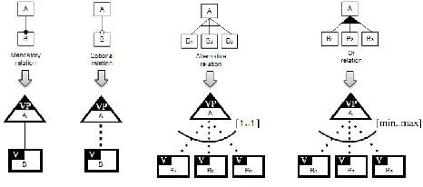
[image:6.612.53.287.258.376.2]A MAP thread relationship which represents an AND/OR relation between strategies is transformed into an Or relation between features. A bundle relationship which represents a XOR relation between two strategies is equivalent to an Alternative relation between features. We have defined new concepts in MAP Meta model which are Mandatory and Optional section. These concepts are transformed as mandatory and optional features. We use the same graphical representation than feature model for the representation of mandatory section and optional one.
Fig. 4. Rules of transformations between MAP model and features
model
The second transformation tries to document the variability established using the analysis view i.e. feature model. This transformation is presented in figure 5. Variability documentation is done using the OVM model which allows us the representation of the variable parts of software product line. Mandatory and optional features are transformed successively as a mandatory and optional relation between variation point and variant. An Alternative relation and an Or relation between features are transformed into a relation between many variants with a cardinality which is consecutively fixed as 1 and min/max value.
Fig. 5. Rules of transformations between features model and OVM
model
Our last transformation deals with feature model and UML class model (into classes and attributes) and is presented in figure 6.
[image:6.612.325.571.301.410.2]A feature can be a simple or composite feature. The leaves of feature tree are simple features and are mapped into an attribute of a parent class. For a not atomic feature (composite), a class will represent the feature. The mandatory features imply a unidirectional association with the right cardinality. In the case of optional features we use an association with 0..1 as cardinality. For alternative and OR groups of features we use generalization. An alternative group of features is represented by a generalization of classes with exclusive as constraint between the subclasses to mention that only one should be chosen. For Or group of features we use a generalization of classes with overlap as constraint between the subclasses to mention that we can chose more than one.
Fig. 6. Rules of transformations between features model and class
model
IV. TOOL SUPPORT
We developed a visual and interactive Tool for requirement modeling, feature capture and architecture modeling which is based on the meta-model presented previously. Our future works will include the integration of feature configuration in this tool. We implements map modeling, cardinality-based feature modeling and OVM modeling. This tool is based on eclipse plugins. We try to use the multiple possibilities of extension offered by eclipse platform throw two very famous plugins which are Eclipse Modeling Framework (EMF) [26] and Graphical Modeling Framework (GMF) [27]. These plugins helps us for the construction of our model driven approach. Providing a tool support for map, feature and class modeling as an Eclipse plugin is considered as beneficial with the integration of these kinds of modeling as part of a development environment.
[image:6.612.54.287.551.654.2]International Journal of Emerging Technology and Advanced Engineering
Website: www.ijetae.com (ISSN 2250-2459,ISO 9001:2008 Certified Journal, Volume 5, Issue 6, June 2015)
408
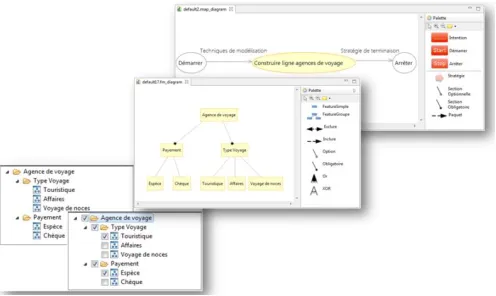
[image:7.612.50.298.186.334.2]We develop not only palettes but also OCL transformations between the different models. In this way models are obtained from a source model using the automate rules of transformations.
Fig. 7. Graphical Palettes and views for MAP/Feature modeling.
We propose also two views for features tree modeling where the first one presents the structure of software product line and the second one presents the configuration of a product line. The configuration concerns the choice of the features existing in the product issued from the software product line. Much amelioration needs to be done to add the generation of the products.
To allow the transformations between the released models we propose a set of QVT transformations. A part of these transformations are presented in figure 8 where we allow the mapping between MAP model and Feature model and the mapping between Feature model and Class model.
Fig. 8. QVT transformations.
Traceability between the different models used in the process is managed using an XML file where we save the details of the models, the transformations between these models and the treated step of SPL lifecycle.
V. RELATED WORK
Many approaches related to feature models and product architectures are proposed in literature. The mapping between requirements and design is a complex task because of the flexibility and adaptability of the SPL, the different technology possibilities… Van Lamsweerde [13] derives software architectures from the formal specifications of a system goal model using heuristics like design elements (classes, states…). Sochos et al. propose a mapping between requirements and architecture by modifying the feature models [21]. Bragança et al. [22] propose the obtaining of features from use case models. Laguna et al. [23] proposes some patterns to obtain design view (class diagram) and use case models from features models.
Expressing variability using UML models (Structural, functional or dynamic models) is proposed by making some change on use case, class or sequence diagrams. Von der Maßen et al. [19] propose the extension of UML Meta model using new relationships "option" and "alternative". Clauß proposes the use of stereotypes to express variability in architecture models [20].
Many propositions are interested on the construction of editor for features modeling. AmiEddi [14] supports the feature modeling notation [4] without the supporting of feature and group cardinalities. CaptainFeature [15] implements a cardinality-based notation. ConfigEditor [11] tries to integrate feature-based configuration. ReqiLine [16] is a tool integrating feature modeling and requirements engineering. This tool allows the definition of various relationships between features but does not support cardinalities and the checking of models for consistency.
In the literature we found not only research tools are
proposed but also some commercial tools like
Pure::Variants [17] or GEARS [18]. The Pure::Variants tool supports feature modeling and configuration using a tree-view render without taking into account the feature cardinalities. It allows modeling of constraints between features and uses Prolog-based constraint solver for the
configuration. GEAR allows the modeling and
International Journal of Emerging Technology and Advanced Engineering
Website: www.ijetae.com (ISSN 2250-2459,ISO 9001:2008 Certified Journal, Volume 5, Issue 6, June 2015)
409
VI. CONCLUSION AND FUTURE WORK
Software product line construction and derivation of particular product become a topic with a growing interest. This paper tries to focus on the mapping of goal-oriented requirements to software product line architectures. In this paper, our contribution was the definition of a Meta-model for the representation of the different concepts used for the construction of Software Product Line. Also we define a process allowing the construction of software product line and the derivation of particular product throw the configuration and model derivation. This process contains an intentional level in both domain engineering and application engineering.
In summary, this paper proposes a process for generating design views using class diagram from a requirement model which is Map model, features model and OVM model. The purpose is to fulfill stakeholder’s requirement of the software product line and the particular requirements. The process is supported by rules and mapping patterns. To support our process, we propose a tool using eclipse plugins (EMF and GMF) to facilitate the construction of SPL.
Our future works include the amelioration of our tool
support to improve the generative aspect. This
improvement will be throwing the formal validation of the proposed rules and mapping patterns. Also we will try to consider another case study to validate our approach. At last we try to generate assets of the software product line. These assets will be product line requirements, analysis models, product line architecture, reusable components and services. We will focus also to propose an adaptive method which can suit the SPL construction situations.
REFERENCES
[1] Clements, P. & Northrop, L. Software Product Lines: Practices and Patterns. Addison-Wesley, Boston, MA, 2001.
[2] Bosch, J. Design & Use of Software Architectures, Adopting and Evolving a product-line approach, Addison-Wesley, 2000.
[3] Van Grup, J. Variability in Software Systems, the key to software reuse (Thesis). Sweden: University of Groningem, 2000.
[4] Czarnecki, K. & Eisenecker, W. Generative Programming: Methods, Tools, and Applications. Addison-Wesley, 2000.
[5] Rolland, C., Prakash, N. and Benjamen, A. A Multi-Model View of Process Modelling, Requirements Engineering Journal, 1999c. [6] Jackson, M. ―Software Requirements & Specifications – a Lexicon
of Practice, Principles and Prejudices‖. ACM Press. Addison-Wesley, 1995.
[7] Kang, K., Cohen, S., Hess, J., Nowak, W. and Peterson, S. Feature-oriented domain analysis (FODA) feasibility study. Technical Report CMU/SEI-90TR -21, Software Engineering Institute, Carnegie Mellon University, Pittsburgh, PA, Nov. 1990.
[8] Griss, M., Favaro, J. and D’Alessandro, M. Integrating feature modeling with the RSEB. In Proceedings of the Fifth International Conference on Software Reuse (ICSR), pages 76–85. IEEE Computer Society Press, 1998.
[9] Lee, K., Kang, K. C. and Lee, J. Concepts and guidelines of feature modeling for product line software engineering. In C. Gacek, editor, Software Reuse: Methods, Techniques, and Tools: Proceedings of the Seventh Reuse Conference (ICSR7), Austin, USA, Apr.15-19, 2002, LNCS 2319, pages 62–77. Springer-Verlag, 2002.
[10] Barbeau, M. and Bordeleau, F. A protocol stack development tool using generative programming. In D. Batory, C. Consel, and W. Taha, editors, Proceedings of the ACM SIGPLAN/SIGSOFT Conference on Generative Programming and Component Engineering (GPCE’02), Pittsburgh, October 6-8, 2002, pages 93– 109. Springer-Verlag, 2002.
[11] Czarnecki, K., Bednasch, T., Unger, P. and Eisenecker, U. W. Generative programming for embedded software: An industrial experience report. In Proceedings of the ACM SIGPLAN/SIGSOFT Conference on Generative Programming and Component Engineering (GPCE’02), Pittsburgh, pages 156–172. Springer-Verlag, 2002.
[12] Soffer P. and Rolland, C. ―Combining Intention-Oriented and State-Based Process Modelling‖, Proceedings of the International Conference on ER’05, LNCS, pp47-62, 2005.
[13] Van Lamsweerde, A. From system goals to software architecture. In Formal Methods for software Architectures, LNCS 2804, 2003. [14] Selbig, M. A feature diagram editor: analysis, design, and
implementation of its core functionality. Diplomarbeit, Fachbereich Informatik, Fachhochschule Kaiserslautern, Standort Zweibrücken, Germany, Oct. 2000.
[15] Bednasch, T., Endler, C. and Lang, M.. CaptainFeature, 2002-2004.
Tool available on Source Forge at
https://sourceforge.net/projects/captainfeature/
[16] Von der Maßen, T. and Lichter, H. RequiLine: A Requirements Engineering Tool for Software Product Lines. In F. van der Linden, editor, Software Product-Family Engineering: 5th International Workshop, PFE 2003, Siena, Italy, November 4-6, 2003.
[17] Pure-systems GmbH. Variant Management with Pure::Consul. Technical White Paper. Available from http://web.pure-systems.com, 2003.
[18] Krueger, C. W.. Software mass customization. White paper.
Available from
http://www.biglever.com/papers/BigLeverMassCustomization.pdf. [19] Von der Massen, T., Lichter, H.: ―RequiLine: A Requirements
Engineering Tool for Software product lines‖. In Software Product-Family Engineering, PFE 2003, Siena, Italy, pp 168-180, 2003. [20] Clauß, M.: Generic modeling using Uml extensions for variability.
In Workshop on Domain Specific Visual Languages at OOPSLA, 2001.
[21] Sochos, P., Philippow, I., Riebish, M.: Feature-oriented development of software product lines: mapping feature models to the architecture. Springer, 2004
[22] Bragança, A., Machado, R. J.: "Automating Mappings between Use Case Diagrams and Feature Models for Software Product Lines", Proceedings of SPLC 2007, Kyoto, Japan, IEEE CS Press, 2007. [23] Laguna, M.A., González-Baixauli, B.: Product Line Requirements:
International Journal of Emerging Technology and Advanced Engineering
Website: www.ijetae.com (ISSN 2250-2459,ISO 9001:2008 Certified Journal, Volume 5, Issue 6, June 2015)
410 [24] Ouali, S., Kraiem, N. and Ben ghezala, H. ―From Intentions to
Software Design using an Intentional Software Product Line Meta-Model‖, in the proceeding of the 8th International Conference on Innovations In Information Technology INNOVATIONS'12, in Al Ain, UAE, 2012.
[25] Rolland, C. & Salinesi, C. Modeling Goals and Reasoning with Them. In Aybüke Aurum & Claes Wohlin, editeurs, Engineering and Managing Software Requirements, pages 189–217. Springer Berlin Heidelberg, 2005.
[26] Eclipse Modeling Framework.
http://www.eclipse.org/modeling/emf/
[27] Graphical Modeling Framework.
http://www.eclipse.org/modeling/gmp/
[28] Halmans, G. & Pohl, K. Communicating the Variability of a Software-Product Family to Customers Journal of Software and Systems Modeling, Springer, 2003.
[29] Jarke, M. & Pohl, K.. Requirements Engineering: An Integrated View of Represenation, Process and Domain, in Procedings 4th Euro. Software Conf., Springer Verlag, 1993.