International Journal of Emerging Technology and Advanced Engineering
Website: www.ijetae.com (ISSN 2250-2459, ISO 9001:2008 Certified Journal, Volume 5, Issue 5, May 2015)
95
A Wireless LAN Based Structural Constraints Special
Care System
Amol B. Mane
1, Dr. G. U. Kharat
2 1,2SGMSPM’s SPCOE,Dumberwadi, Pune, India
Abstract—This system is able to transmit the parameters of patients continuously over a long distance by wireless LAN. Due to monitoring system, a quick treatment is given to the patient and it saves patient life. This is convenient process to monitor the patient’s health conditions from anywhere. The Sensor acknowledges the sensed input parameter to the LPC2148 controller and conveys through transmitter. At the receiver, the received parameters are displayed on a PC monitor. In case of emergency and critical situations the proposed system alerts the doctor immediately with the status of the patient. The result displays the various parameters reading through wireless LAN by using IP address on LAN connected PC in hospital. This project is a kind of scheme used for admitted patient in hospital and the communication techniques to cover large area.
Keywords—LPC2148, RF Modem, LM 35, Blood pressure sensor, Heart beat sensor.
I. INTRODUCTION
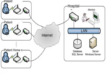
[image:1.612.347.531.233.361.2]Currently there are number of health monitoring system available for the patients, but all these system works mainly when there is emergency occurs. It means that, the information is transmitted to server mainly when there is any abnormality occurs. But main problem with this system is that it is not capable of transmitting data continuously. Also the range is limited for different wireless technologies used in systems. So, overall process becomes time consuming & not suitable in emergency situations. Hence to overcome these limitations of system we have proposed a new system which is able to transmit the parameters of patients continuously & over a long distance by wireless LAN. This project deals with the monitoring of the patient parameters such as Body temperature, Heartbeat, and Blood pressure. For measurement of these parameters we need sensors which respond to the changes in the parameters appropriately. In this project the reading of patient and all information is collecting through the sensors and send to the receiver by using RF transmitter. The received information then displayed on all pc monitor connected through wireless LAN. It also used to shows which critical patient admitted in ward as shown in figure1.
Figure 1 Patient monitoring system
II. MAIN BLOCK DIAGRAM
The Main Block Diagram OF Project is shown in figure it consist of LPC2148,Line Driver, RF TRANSMITTER module.LPC2148 Connected to line driver and line driver connected to RF TRANSMITTER module and lpc2148 connected to various block these block namely Heart Beat Sensor, Blood Pressure Sensor, Body temperature sensor. This particular sensor gives reading and connected to lpc2148 heart beat sensor gives heart reading (BPM) in 069, 070, 71, 72 etc. takes reading in following format. Blood pressure gives reading in (mm hg), bodytemperature in farad. All connected to LPC2148 through max 232 through transmitter RF TRANSMITTER module Through Receiver side RF TRANSMITTER Module.
[image:1.612.331.558.566.647.2]International Journal of Emerging Technology and Advanced Engineering
Website: www.ijetae.com (ISSN 2250-2459, ISO 9001:2008 Certified Journal, Volume 5, Issue 5, May 2015)
96 A) Receiver Side
[image:2.612.54.278.197.315.2]The receiver side block diagram consist of three block wireless connection means all pc in LAN connected and another section LPC 2148 connected to Ethernet controller through pc .
Figure 3 Block Diagram of Receiver
The LPC 2148 here is behaving like a HTTP server. It shall host the web page containing the patient information like BP, HB and body temperature. This web page can be seen from any PC in the network.
III. HARDWARE DESCPIPTION
A) Arm Controller LPC2148
The LPC2142/2148 microcontrollers are based on a 32/16-bit ARM7TDMI-S CPU with real-time emulation and embedded trace support, that combines the microcontroller with 64 KB and 512 KB of embedded high-speed flash memory. A 128-bit wide memory interface and unique accelerator architecture enable 32-bit code execution at the maximum clock rate. For critical code size applications, the alternative 16-bit Thumb mode reduces code by more than 30 % with minimal performance penalty.
Due to their tiny size and low power consumption, LPC2142/2148 are ideal for applications where miniaturization is a keyrequirement, such as access control and point-of-sale.
I) Key Features:
1)16/32-bit ARM7TDMI-S microcontroller in a tiny LQFP64 package.16 KB/40 KBof on-chip static RAM and 64 KB/512 KB of on-chip Flash program memory.
2)128-bit wide interface/accelerator enables high-speed 60 MHz operation.
3)USB 2.0 Full-speed compliant device controller with 2 KB of endpoint RAM
4)Two 32-bit timers/external event counters
5)Low power Real-Time Clock (RTC) with independent power.
6)Up to 45 of 5 V tolerant fast general purpose I/O pins in a tiny LQFP64 package.
7)A 60 MHz maximum CPU clock available from programmable on-chip PLL
8)On-chip integrated oscillator operates with an external crystal in range from 1 MHz to 30 MHz and with an external oscillator up to 50 MHz
9)Processor wake-up from Power-down mode via external interrupt or BOD.
B) Wireless Serial Communication RF Modem
RF modem can be used for applications that need two way wireless data transmission. It features adjustable data rate and reliable transmission distance. The communication Protocol is self-controlled and completely transparent to user interface. The module can be embedded to your current design so that wireless communication can be set Up easily.
Figure 4 Wireless Serial Communication RF Modem
I) Features
1)Automatic switching between TX and RX mode. 2)FSK technology, half duplex mode, robust to
interference.
3)2.4 GHz band, no need to apply frequency usage license.
4)High sensitivity, reliable transmission range. 5)Stable, small size, easier mounting.
6)Error checking (CRC) of data in built.
II) Application
1) Sensor Networks / Data collection 2) Wireless metering
[image:2.612.337.549.408.482.2]International Journal of Emerging Technology and Advanced Engineering
Website: www.ijetae.com (ISSN 2250-2459, ISO 9001:2008 Certified Journal, Volume 5, Issue 5, May 2015)
97
IV. SENSORS
A) Blood Pressure Sensor 3765
[image:3.612.361.528.481.631.2]Blood Pressure Play important role in daily life because BP high & low BP has causes effect on human body. Blood pressure readings have two numbers, for example 140/90mmHg.The top number is your systolic blood pressure.
Table I
blood pressure reading for seven people.
The bottom one is your diastolic blood pressure. (The lowest pressure when your heart relaxes between beats.) Depends On Systolic & Diastolic Reading shows the patient health whenever the reading less than 120&less than 80 this condition shows normal blood pressure category. When the systolic 120–139 or diastolic 80–89 this condition shows pre hypertension. Other is systolic reading 140 – 159 or diastolic reading 90 – 99 this condition shows High Blood Pressure (Hypertension) Stage1. When systolic reading160 or higher or diastolic 100 or higher this condition shows High Blood Pressure(Hypertension) Stage2. When systolic reading Higher than 180 or diastolic Higher than 110 this condition shows Hypertensive Crisis(Emergency care needed). All the reading is gives blood pressure for systolic, diastolic and the range plot in the table and the table shows conditions for patient.
Graph I shows Reading systolic & diastolic
A graph shows systolic diastolic and patient blood pressure. On x axis shows different Patients axis Shows Systolic, Diastolic Blood pressure.
P1- indicates emergency care needed.
P2- indicates hypertension (high blood pressure stage 1).
P3 -indicates normal blood pressure.
P4 -indicates pre hypertension. P5 -indicates pre hypertension
P6 -indicates hypertension (high blood pressure stage 2)
P7-indicates hypertension (high blood pressure stage 2)
I) Specifications
Blood Pressure & Pulse reading are shown on display with analog out for external projects of embedded circuit processing and display. Shows systolic, diastolic and pulse readings. Compact design fits over your wrist like a watch. Easy to use wrist style eliminates pumping.
II) Features
1)Intelligent automatic compression and decompression 2)Easy to operate, switching button to start measuring 3)60 store group’s memory measurements
4)Can read single or all measures
5)3 minutes automatic power saving device
6)Local tests for : wrist circumference as 135-195mm 7)Fully Automatic, Clinical Accuracy, High-accuracy 8)Analogy output voltage for external circuit processing
or display
.
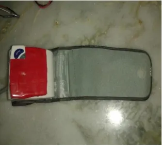
Figure 5 pressure sensor
B) Heart Beat Rate Sensor
By using heart beat sensor in bpm is useful to identify the age of patient and also use full shows standard of heart beat in bpm.
parameter p1 p2 p3 p4 p5 p6 p7
Systolic 192 158 120 122 137 180 162
[image:3.612.49.287.518.679.2]International Journal of Emerging Technology and Advanced Engineering
Website: www.ijetae.com (ISSN 2250-2459, ISO 9001:2008 Certified Journal, Volume 5, Issue 5, May 2015)
98
The heart beat is required status of fitness for living people in healthy life according to age the heart beat rate is change .the new born baby to 20 years age person the heart beat range is 140-170 .21 years 30 years age gives the reading 133-162. 31 years 40 years age gives the reading 126-153.41years 50 years age gives the reading 119-145.51 years 60 years age gives the reading 112-136.61 years 70 years age gives the reading 105-128.71 years 80years age gives the reading 98-119.81 years 90 years age gives the reading 91-110.91 years 100 years age gives the reading 84-101.
[image:4.612.324.582.141.294.2]We are taking the seven person reading & by using this I am identify the patient condition & guessing about the age of patient .the reading for heat beat& body temperature
Table II
Heart Beat Reading For Seven People
Parameter P1 P2 P3 P4 P5 P6 P7
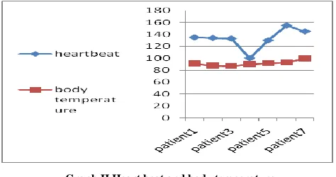
Heartbeat 135 134 133 100 130 155 145 Body
Temperature 91 88 87 90 92 93 100
I) Heartbeat and body temperature
The graph shows the reading for the patients. This reading is useful to live the healthy people.
Graph II Heart beat and body temperature
On y axis heart beat and body temperature on y axis seven patient.
[image:4.612.41.296.308.408.2]C) Body temperature Sensor
Figure 7 Temperature sensor
I) Features:
1)Calibrated directly in ° Celsius (Centigrade)
2) Rated for full −55° to +150°C range
3) Low cost due to wafer-level trimming
4) Operates from 4 to 30 volts 5) Less than 60 μA current drain
6) Low self-heating, 0.08°C in still air
V. RESULT
The Result Displays the various parameter reading through wireless LAN through internet by using IP address the reading display on lan connected pc in hospital.
[image:4.612.48.285.456.581.2]International Journal of Emerging Technology and Advanced Engineering
Website: www.ijetae.com (ISSN 2250-2459, ISO 9001:2008 Certified Journal, Volume 5, Issue 5, May 2015)
99
VI. CONCLUSION
This project is a kind of scheme of wireless LAN based structural constraints special care system on admitted patient in hospital. An idea proposed here is advantageous over the useful in medical sector for monitoring various parameter measures such as Blood Pressure, Heart Beat, and Body Temperature. The wireless LAN is solved by using RF transceiver and the communication techniques. To cover large area LAN is used. With little modification in hardware and software other functionality can be implemented. This proposed idea accompanied by Home health care monitoring system provides better solution for home health monitoring system.
A) Application
1. Used in hospital general ward, ICU, where critical condition patients are admitted.
2. To observe continuously patient condition by using various parameters and display it on web page.
B) Future Work
Use GPS and GSM, to regularly monitor patient behavior via SMS and location in multi specialty hospital, ICU. In All wards, admitted patient history display on all pc available in hospital also in home monitoring system or mobile.
REFERENCES
[1] M.Karandeep, S. C. Mukhopadhyay, Fellow, J. Schnepper, M.Haefke, And H.Ewald, ―Zigbee-Based Wearable Physiological Parameters Monitoring System”, In IEEE Sensors Journal, March. 2012 Vol.12, pp.423-430.
[2] A.Nagarkar And M.N.Kakatkar, ―Zigbee Based Wireless Patient Monitoring, "in IJSETR, February.2013, vol. 2, pp. 304–308. [3] B. Sirisha, T.Sraddh and K. Vijayanand, ―Real-Time Multi Patient
Monitoring System Using Arm And Wireless Sensor Network, "in IJCNS, March.2013, vol. 2, pp. 41–47.
[4] P. Corbishley and E. Rodríguez-Villegas, ―Breathing detection: Towards a miniaturized, wearable, battery-operated monitoring system,‖ IEEE Trans. Biomed. Eng., , Jan. 2008, vol. 55, no. 1, pp. 196–204.