International Journal of Emerging Technology and Advanced Engineering
Website: www.ijetae.com (ISSN 2250-2459,ISO 9001:2008 Certified Journal, Volume 4, Issue 9, September 2014)
663
Effect on Magnetic Abrasive Machining with Different Range
of Electrical Parameters
Rishi Dev Joshi
1, Dr. Gursewak Singh Brar
2, Mithlesh Sharma
3 1Rishi Dev Joshi BBSBEC, Fatehgarh Sahib
2Dr. Gursewak Singh Brar BBSBEC, Fatehgarh Sahib
3Mithlesh Sharma IET Bhaddal
Abstract— Magnetic abrasive machining is a surface finishing technique in which a magnetic field is used to force abrasive particles against the target surface. As such, finishing of conventionally inaccessible surfaces (e.g., the inside surface of a long curved pipe) is possible. The aim of this paper is to study maximum efficiency in terms of material removal rate with respect to magnetic flux density with respected to the different types of coils. Magnetic abrasive finishing is an efficient tool for internal finishing of bent tubes. In this research work SS 304, cast iron and brass cylindrical work piece was finished using a magnetic abrasive finishing process so as to study the effect of magnetic flux density on material removal rate with respect to various parameters so as to find the best parameters at a particular range of electromagnetic flux coil. A cylindrical workpieces was finished using a magnetic abrasive finishing process on an apparatus developed for carrying out testing work. The process principle and the finishing characteristics of magnetic abrasive finishing of cylindrical pipes using sintered magnetic abrasives are described in this paper. The sintered magnetic abrasive is a mixture of Al2O3 abrasive and ferromagnetic
particles. Results showed maximum efficiency on a medium range of magnetic flux density.
Keywords— Abrasive, Magnetic Abrasive Machining, surface finishing
I. INTRODUCTION
Surface finish has a vital influence on important functional properties such as wear resistance and power losses due to friction on most of the engineering components. With the use of advanced engineering materials, the machining process becomes difficult and precision surface finish is not produced by the existing machine tools. Therefore fine finishing processes are employed in machining the surface of many critical machined components to obtain a very high surface finish apart from high dimensional accuracies. Such Magnetic abrasive machining (MAM) is a precise polishing method in which the cutting tool is a group of magnetic abrasive particles (MAPs), and the cutting force is controlled by the magnetic field in the working gap.
International Journal of Emerging Technology and Advanced Engineering
Website: www.ijetae.com (ISSN 2250-2459,ISO 9001:2008 Certified Journal, Volume 4, Issue 9, September 2014)
664
Finishing of bearings, precision automotive components, shafts, and artificial hip joints made of oxide ceramic and cobalt alloy are some of the products for which this process can be applied. A magnetic abrasive finishing process is a nontraditional process that employs magnetic field action and mixed magnetic abrasives [2-5].
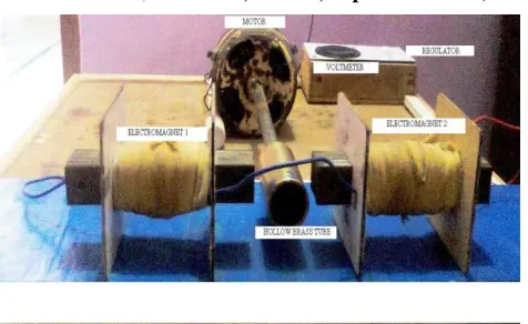
II. EXPERIMENTAL SET-UP
A schematic of experimental set up is shown in figure 1, which embodies the principles of internal finishing described in the previous section. The experimental setup has major components like electromagnet (1K Gauss, 3K Gauss), control unit, A.C. motor, and variable A.C. supply. The main elements of MAF equipment include the electromagnet (1K Gauss), variable A.C. supply and abrasive powder (Sintered Al2O3 + Fe). The cylindrical
work piece i.e. SS304, CI and brass pipe, was held in the chuck attached to A.C. motor and abrasives were packed in the pipe and over the oneend cap is provided with the help of dead centre to kept the abrasive inside of pipe. Magnetic field was applied to the abrasives by electromagnet. Magnetic field strength is varied for experimentation with the help of variable A.C. supply. Electromagnet plays an important role in present experimentation. The space between work piece and electromagnet is kept constant initially. The magnetic field strength depends upon weight percentage of the magnetic particles, present in the magnetic abrasive powder. Both the working gap and size of the work piece are taken into consideration, while designing. The objective of the design is to give rotational motion to the cylindrical work piece. The work piece is rotated at 1200, 1280 and 1360 rpm. An AC motor is chosen for providing rotational motion to the work piece. A working view of the setup is shown in the figure 1. Magnetic abrasive particles through magnetic pressure finish the work piece. Al2O3 based sintered magnetic
abrasives are used as magnetic abrasives. The Al2O3 based
[image:2.612.327.565.129.275.2]sintered magnetic abrasives have been developed in sintering machine. The process parameters were the gap between work piece and magnet, rotational speed of work piece, magnetic flux density, current, concentration of particles and the work piece gap. The improvement of surface roughness was achieved due to the vibrational motion occurring in the particles effectively removes unevenness in rotational direction and direction orthogonal to it.
Figure: 1 working model of electromagnetic abrasive finishing
III. EXPERIMENTAL CONDITIONS
In this work Al2O3 based sintered magnetic abrasives
were used for internal finishing of cylindrical SS304, CI and brass pipes. The Alumina (Al2O3) based sintered
magnetic abrasives were prepared by blending of Al2O3
(50%) of 300 mesh size (74μm) and iron powders (50%) of 300 mesh size (51.4μm), compacting them by using a Universal Testing Machine (UTM), sintering the mixture in a sintering set up at 1100°C in H2 gas environment,
[image:2.612.321.568.613.712.2]crushing the compacts into small particles and then sieving todifferent ranges of sizes. The obtained sizes are 200μm, 300μm, and 400μm.The experimental conditions are shown in table no.1 Cylindrical Brass, SS305 and CI pipes (Ø34 x80 mm) were used for the experiments as work pieces. In this work, experimental variables such as concentration, gap between work piece and pole and machining time were considered for the study purposes. Effect of various parameters with respect to MFD was studied out w.r.t. material removal rate. The finishing characteristics of magnetic abrasives were analyzed by measuring the surface roughness, which was measured at four points before and after finishing using a Mitutoyo surface roughness tester (SJ-210P) having a least count of 0.001 μm (cut off length = 2.5 cm)and roughness on average scale reading is taken.
Table I
Experimental Conditions Of Work Piece
Abrasive grain size 200μm,300μm,400μm
Magnetic pole SS 400:Material
Work piece SS 304,CI and Brass tubes
Revolution 1200,1280 and 1360 rpm
Magnetic abrasives Aluminium oxide Al2O3 ,Ferrite particles Magneticflux density 3000 and 1000 gauss
Currents 0.2,0.3 and 0.4A
Gap between work pieceand pole
International Journal of Emerging Technology and Advanced Engineering
Website: www.ijetae.com (ISSN 2250-2459,ISO 9001:2008 Certified Journal, Volume 4, Issue 9, September 2014)
665
IV. EXPERIMENTATION
In experimentation part firstly setup was prepared having two different coils having different number of coils as a result of there is a range of magnetic flux density on which testing will be carried out. Three specimens were selected for experimentation.Work piece consist of cylindrical tube in which mixture of aluminium oxide and iron oxide is placed, initial reading before testing and after testing is taken so as to study out the effect of various parameter on the surface finish of work piece.
V. RESULTS AND DISCUSSIONS
To establish the feasibility of usage of MAM, the experiments were conducted by selecting the process parameters based on the findings of trial runs and some of the parameters influence is discussed below. Range of magnetic flux density has been taken for comparative study i.e.1000 and 3000 Gauss. With respect to these MFD study was carried out to find the effect of work piece on circumferential speed, standoff distance and time, on surface finish of work piece. In this study, the rotational speeds of 1200,1280 and 1360 rpm are taken with duration of machining as 15, 30 and 45 minutes were taken for experimentation. It was observed that the improvement in surface finish is more with the medium range of standoff distance and machining time. The improvement insurface finish can be due to more abrasives that come in contact with the work piece during experimentation.
A. Influence of gap between work piece and magnetic pole
on surface finish at 1000 Gauss MFD
Figure 2, illustrates the effect of gap between the work piece and the magnetic poles on work surface finish with respect to 1000 Gauss MFD. The gap considered for the experimentation was 5, 15 and 30 mm and the machining duration was 45 minutes. It can be seen that the work piece clearance of 5mm with Al2O3 abrasive grit contributed to
[image:3.612.323.566.119.245.2]an improvement insurface finish. Similar trend was noticed with SiC grits also it was found that maximum MRR was taken in case of Cast iron at a standoff distance of 15mm. it may be due to strong magnetic field created by coils as a result of which the mixture particles are attracted towards the wall of the cylinder tubes. In this case maximum machining to be occurred in case of brass at 30 mm standoff distance and in all other cases maximum material removal rate occurred at a distance of 15mm.
Figure 2: shows improvement in surface finish w.r.t standoff distance of coil from work piece.
B. Influence of Time of machining on surface finish at
1000 Gauss MFD
[image:3.612.322.562.442.568.2]Figure 3, illustrates the effect of machining time on surface finish of the work piece with respect to 1000Gauss MFD. The time considered for the experimentation was 15, 30 and 45 minutes. It can be seen from the figure that maximum material removal rate was taken place at 45 minutes in all the cases of materials but maximum material finish occurred in case of brass.In this case maximum surface improvement will take place at duration of 45 minutes. It may be due to striking of particles with tubes wall again and again as a result hardness of particles may be getting reduced and due to which material removal takes place.
Figure 3: Shows improvements in surface finish w.r.t time of machining.
C. Influence of concentration of powder on Surface Finish
at 1000 Gauss MFD.
Figure 4, illustrates the effect of concentration of powder on the surface finish which was studied with respect to 1000 Gauss MFD and at a speed of 1280 rpm.The time considered for the experimentation was 30 minutes. It can be seen from the figure that maximum material removal rate was taken place at concentration of 3:1 ratio of Al2O3
and ferrite particles in all the cases of materials except SS304 but maximum material finish occurred in case of brass.
0 2 4 6
5 15 30
im
p
ro
ve
m
e
n
t
in
su
rface
fi
n
ish
,
µm
Stand off distance ,mm
BRASS CI SS-304
0 1 2 3 4
15 30 45
im
p
ro
ve
m
e
n
t
in
su
rface
fi
n
ish
,
µm
TIME,mins
International Journal of Emerging Technology and Advanced Engineering
Website: www.ijetae.com (ISSN 2250-2459,ISO 9001:2008 Certified Journal, Volume 4, Issue 9, September 2014)
666
[image:4.612.49.288.210.305.2]As we see from the figure that with increase in abrasive aluminum oxide, material removal rate increases. The reason behind it may be due to the increase in number of abrasive particles as we know that more the number of abrasive particles more will be the surface finish so it increases the material removal rate of the material
Figure 4: shows improvement in surface finish w.r.t. concentration of aluminium oxide to ferrite particles.
D. Influence of gap between work piece and magnetic pole
on surface finish at 3000 Gauss MFD
Figure 5, illustrates the effect of gap between the work piece and the magnetic poles on work surface finish with respect to 3000 Gauss MFD. The gap considered for the experimentation was 5, 15 and 30 mm and the machining durationwas 45 minutes. It can be seen that the work piece clearance of 30mm with Al2O3 abrasive grit contributed to
[image:4.612.325.566.244.379.2]an improvement in surface finish in case of brass. It was found that maximum MRR was taken in case of cast iron will be at a standoff distance of 15mm it may be due to strong magnetic field created by coils as a result of which the mixture particles are attracted towards the wall of the cylinder tubes. In case of stainless steel all the standoff distance have same MRR. So overall we can say that stand offdistance of 15 mm is best as it has shown good results.
Figure 5: shows improvement in surface finish w.r.t standoff distance of coil from work piece.
E. Influence of Time of machining on surface finish at
3000 Gauss MFD
Figure 6, illustrates the effect of machining time on surface finish of the work piece with respect to 3000 Gauss MFD.
The time considered for the experimentation was 15, 30 and 45 minutes. It can be seen from the figure that maximum material removal rate was taken place at 30 minutes in all the cases of materials but maximum material finish occurred in case of brass. As we had seen that in starting material removal rate is less with increase in time from 30 to 45 min it had increase after 45 min it had again decreases it may be due blunt of abrasive particles due to its earlier use.
Figure 6: shows improvements in surface finish w.r.t time of machining.
F. Influence of concentration on Surface Finish at 3000
Gauss MFD
Figure 7, illustrates the effect of concentration of powder on the surface finish which was studied with respect to 3000 Gauss MFD and at a speed of 1280 rpm. The time considered for the experimentation was 30 minutes. It can be seen from the figure that maximum material removal rate was taken place at concentration of 2:2 ratio of Al2O3 and ferrite particles in all the cases of materials
except SS304 but maximum material finish occurred in case of brass. As we see from the figure that with increase in abrasive aluminum oxide, material removal rate increases. The reason behind it may be due to the increase in number of abrasive particles. As we know that more the number of abrasive particles more will be the surface finish, so it increases the material removal rate of the material but in this case we found that with increase in concentration of aluminium oxides particles it has not increased tremendously as it may be due to striking of abrasive particles with each other and also as ferrite particles are lesser so due to it lesser number of particles are attracted towards outer wall of cylinder, as a result of which less machining will be there.
0 5 10
1:3 2:2 3:1
Im
p
ro
ve
m
e
n
t
in
su
rface
fi
n
ish
,
µm
Concentraion of Al2O3 to ferrite mixture
BRASS CI SS 304
0 2 4
5 15 30
im
p
ro
ve
m
e
n
t
in
su
rface
fi
n
ish
,
µm
Stand off distance, mm
BRASS CI SS304
0 2 4 6
15 30 45
im
p
ro
ve
m
e
n
t
in
su
rface
fi
n
ish
,
µm
Time,mins
[image:4.612.48.290.525.630.2]International Journal of Emerging Technology and Advanced Engineering
Website: www.ijetae.com (ISSN 2250-2459,ISO 9001:2008 Certified Journal, Volume 4, Issue 9, September 2014)
[image:5.612.49.291.117.260.2]667
Figure 7: shows improvement in surface finish w.r.t. concentration ofaluminium oxide to ferrite particles.
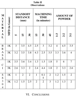
Table II Observations
M A T E R I A L MF
D (i
n
G
a
u
ss
)
STANDOFF DISTANCE
(mm)
MACHINING TIME (in minutes)
AMOUNT OF POWDER
5 15 30 15 30 45 1:3
2
:2
3
:1
B R A S S
1K 3 3.5 4.5 2.5 3 3.2 4 4.5 3.5
3K 3.2 3.5 3.8 4.3 2.5 3.5 3.3 3.6 4
C I
1K 3.5 3.6 3.4 1.3 1.5 1.8 5 6 7
3K 2.6 3.3 2 2.4 4.4 1.8 2 3.3 2.6
S S 3 0 4
1K 1 2 2 1 0.1 5
2 1.2 1.5 2
3K 1.2 1.5 2.5 2 2 3 1.2 1.3 2
VI. CONCLUSIONS
This research work showed the feasibility of using Al2O3
basedsintered magnetic abrasive particles for the internal finishing of cylindrical brass, CI and SS304 pipes and gained an understanding of the mechanism involved. Polishing of cylindrical work piece was developed using available abrasives. A machining setup was developed for carrying out study. The set up was prepared so that electromagnet will be placed on both side of a work piece holding mandrel was supported between the chuck and another end of cylindrical tube.
The experimentation with these process parameters reduced thesurface roughness value on a cylindrical component from an initial Ra value of 0.257μm to 0.075μm Ra over a machining duration of 15 minutes with Aluminum Oxide, 220 grit semi magnetic abrasives. These studies also indicated the need to consider the work piece initial roughness, apart from its hardness for achieving an improved finish on the work surface.From table 2, following conclusions has been made:-
From these studies it was clear that work piece having initial roughness around 0.4μm Ra is found to give a significant improvement in surface finish with semi magnetic abrasive machining.
Study shows that on various parameters improvement in surface finish is maximum in case of brass as compared to other materials.
It has been found that with the increase in number of turns in a coil magnetic flux density also increases as a result of which maximum material removal rate will be occurring.
An effort has been made out to find out the best parameters for abrasive machining with respect to various parameters so that maximum machining will take place.
Acknowledgement
The authors are thankful to all the faculty and staff members of theKalsiEngg. Works, Nangal for providing me necessary facilities. The co-operation attitude of all the laboratory technicians’ and attendants of this department is worth appreciating. The authorswish to thank Mr. M. Sharma who had conducted all themechanical tests at their organization.
VII. FUTURE SCOPE
In addition to the present work further work can be done in following directions:
1. In future study we can work out for finding out the more materials that can be machined by this machining.
2. Different coils effects can be study out in future. 3. The effect of then surface roughness, roundness, micro
diameterchangew.r.t concentration of powder can be studied.
4. Study can be conducted further for finding out the optimumrange of various parameters to find maximum improvementin surface finish.
5. Effect of thickness of cylindrical tube w.r.t. machining and surface finish can be studied.
0 2 4 6
1:3 2:2 3:1
im
p
ro
ve
m
e
n
t
in
su
rface
fi
n
ish
,
µm
concentration of aluminium oxide to …
[image:5.612.44.295.285.602.2]International Journal of Emerging Technology and Advanced Engineering
Website: www.ijetae.com (ISSN 2250-2459,ISO 9001:2008 Certified Journal, Volume 4, Issue 9, September 2014)
668
6. Effect of magnetic property of material on machining can be studied out for future use.
REFERENCES
[1] D. Tudor and D. Andrea, “Magneto-Abrasive Finishing of Complex Surfaces”, Nonconventional Technologies Romania, December, 2013, pp. 31-36.
[2] M. Sharma, D. P. Singh, “To Study the Effect of Various Parameters on Magnetic Abrasive Finishing”, IJRMET Vol. 3, Issue 2, May - Oct 2013, pp. 212-217.
[3] M.G. Patil, Kamlesh Chandra, P.S. Misra, “Study of Mechanically Alloyed Magnetic Abrasives in Magnetic Abrasive Finishing”, International Journal of Scientific & Engineering Research Volume 3, Issue 10, October-2012, pp. 1-5.
[4] Y. M. Hamad, “Improvement of Surface Roughness Quality for Stainless Steel 420 Plate Using Magnetic Abrasive Finishing Method”, Al-Khwarizmi Engineering Journal, Vol. 6, No. 4,(2010), pp. 10-20.
[5] Rohit Rampal, “Comparing the Magnetic Abrasives by Investigating the Surface Finish”, Journal of Engineering, Computers & Applied Sciences (JEC&AS) Volume 1, No.1, October 2012, pp. 20-24.
[6] Yan Wang and Dejin Hu, “Study on the Inner Surface Finishing ofTubing by Magnetic Abrasive Finishing”, International Journal of Machine Tools & Manufacture, 45, 2005, pp. 43-49.
[7] Dhirendra K. Singh, V.K. Jain, V. Raghuram and R. Komanduri, “Analysis of Surface Texture Generated by a Flexible MagneticAbrasive Brush,”Wear. 259, 2005, pp. 1254-1261. [8] Shinmura. T, Takazava. K and Hatano T., “Study on Magnetic
Abrasive Process-Application to Plane Finishing”, Bulletin of Japan Society of Precision Engineering, Vol. 19(4), 1985, pp. 289-291. [9] Yamaguchi. H and Shinmuira. T, “Study of the Surface Modification
Resulting from an Internal Magnetic Abrasive Finishing Process”, Wear.225-229, 1999, pp. 246-255.
[10] Dhirendra K. Singh , V.K.Jain ,V. Raghuram , “Super finishing of alloy steels using magnetic abrasive finishing process”, annual report 2003.