International Journal of Emerging Technology and Advanced Engineering
Website: www.ijetae.com (ISSN 2250-2459,ISO 9001:2008 Certified Journal, Volume 3, Issue 6, June 2013)
430
Analyze and Implementation of Green Computing In
Organization Performance
J. R. Arunkumar
1, A. Seenuvasan
21
Assistant Professor, Dhaanish Ahmed College of Engineering, Chennai
2P.G Student, M.E - Computer Science and Engineering, Dhaanish Ahmed College of Engineering, Chennai
Abstract— Till now, green computing research has mostly relied on few, short-term power capacity to illustrate the energy use of undertaking computing. This paper brings new and inclusive power datasets through power and deployment of the IT systems in the academic building. I have collected power data from many individual computing devices and have monitored a subset of CPU and network loads. This intense, long-term monitoring allows us to project the data to a detailed breakdown of temperature and electricity use across the building’s computing systems. Our datasets endow with a chance to examine theory universally made in green computing. We show that power inconsistency both between parallel devices and over time for a particular device can lead to cost or sa V-INgs approximately that are off by 15-20%. Extending the reporting of calculated devices and the duration considerably reduces temperature and electricity. Finally, our occurrence with collecting data and the subsequent analysis lead to a better understanding of how one should go about power classification revision.
Keywords— Centralized AC to DC Converter, Green computing, Reduce conversion losses.
I. INTRODUCTION
Common sense tells us that there are prospect to reduce the energy waste of computing systems. Our electric power system was designed to move central station alternating current (AC) power, via high-voltage transmission lines and lower voltage distribution lines, to organization and businesses that used the power in incandescent computers, laptops, printers, lights other Alter native current devices. Today‘s end user apparatus and tomorrow‘s distributed renewable making requires us to reorganize this model. Electronic devices (such as Personal computers, laptops, changeable speed drives, and business appliances and equipment) need direct current (DC) input. However, all of these DC devices require conversion of the building‘s AC power into DC for utilize, and that conversion classically uses incompetent rectifiers. Moreover, spread renewable production (such as rooftop solar, wind) produces DC power but must be converted to AC to tie into the building‘s electric organism, only later to be re-converted to DC for many end uses.
These AC-DC conversions (or DC-AC-DC in the case of rooftop solar) result in substantial energy losses.
One possible solution is a centralized DC convertor in DC power grid, which is a DC grid within a organization (or serV-INg several buildings) that minimizes or eliminates entirely these conversion losses. In the DC power grid system, AC power converts to DC when entering the DC grid using a high-competence rectifier, which then allocates the power in a straight line to DC equipment served by the DC grid. On typical, these systems trim down AC to DC conversion losses from an average loss of about 32% down to 10%. From individual converter and other distributed DC generation can be fed directly to DC equipment, via the DC power grid, without the double conversion loss (DC to AC to DC), which would be necessary if the DC production output was fed into an AC system.
International Journal of Emerging Technology and Advanced Engineering
Website: www.ijetae.com (ISSN 2250-2459,ISO 9001:2008 Certified Journal, Volume 3, Issue 6, June 2013)
431
The paper goes on to measure one PC (95W active) and uses it to calculate potential energy saV-INgs of their proposed solution. If we were to continue on citation trails like the one above, we risk using limited and possibly outdated data for new systems‘ evaluation. Fast-paced improvements in personal computing mean that some newer, more powerful PCs are also more power-hungry than the 60- to 100-watt range. In addition, enterprise environments are often heterogeneous and it is beneficial to have power measurements from a larger selection of devices. This paper helps fill the power data gap by characterizing energy data at the individual– and the building–scale levels.
The answers to these questions from the fundamental contributions of this paper: Detailed examination of where energy goes reveals that over 50% of the electricity is spent on converter AC to DC converter. PC‘s account for 17% of the bill despite the fact that their utilization is very low. Networking equipment comes at 3.5% and shows no temporal changes despite variations in traffic load. Data analysis shows that estimating saV-INgs based on a few isolated desktop measurements is prone to errors due to the wide spread of PC power draws. Assuming that a day of power is representative and using it to calculate yearly values can be off by as much as 20%. Our deployment and data studies expose the relative importance of device coverage versus duration of deployment. Once a deployment is past the first month of data collection, one must prioritize the ‗what to measure‘ question over the time scale of the study. The rest of this paper reviews the current state of green computing data before diV-INg into the analysis of the Power grid datasets. Along the way, it confirms or refutes a number of anecdotal observations, stressing the need for empirical data. The paper closes with guidelines for the design of future energy characterization studies.
II. BACKGROUND
Up until recently, the green computing community has had to rely on limited energy datasets, requiring researchers to make various explicit and implicit assumptions about the
energy behavior of computing systems. This section
discusses some of the different ways in which related work has procured, used, and analyzed power data in the context of evaluating systems‘ research. At the end of the section, we formulate four common assumptions made in the context of green computing.
A modeling approach that takes system subcomponents into consideration was used SMPS in CPU.
Instead of collecting measurement with a meter, the authors use hardware components power models and software counters to calculate the power draw of a PC. This methodology was able to predict the power use of one machine based on a different one with 20% accuracy, indicating that even more sophisticated techniques that take device subcomponents into consideration will show error in estimation when assuming that similar equipment has similar power or usage behavior.
The industry drive toward less important, lighter and more resourceful electronics has led to the development of the Switch Mode Power Supply (SMPS). There are several topologies commonly used to put into service SMPS. This submission note, which is the primary of a two-part sequence, explains the essentials of unusual SMPS topologies. Applications of unusual topologies and their pros and cons are also thrash out in aspect. This application note will channel the user to decide on an suitable topology for a given function, while given that useful in sequence regarding selection of electrical and electronic mechanism for a given SMPS design.
DC power grid technology:
The Energy Independence and Security Act of 2007, Title XIII, identifies the elements that characterize the ―Smart Grid‖ policy goals. In summary, these are:
R
eliability: security; storage; distributed generation energy efficiency; sustainability; renewable inputs
IT/communications leverage/full cyber-security
load awareness; demand side management; plug-in
vehicles
lowering unnecessary barriers to achieV-INg the
above
International Journal of Emerging Technology and Advanced Engineering
Website: www.ijetae.com (ISSN 2250-2459,ISO 9001:2008 Certified Journal, Volume 3, Issue 6, June 2013)
432
The U.S. Department of Energy (DOE), the California Energy Commission (CEC), the Electric Power Research Institute (EPRI), several utilities and many entrepreneurs and investors have sought through Smart Grid initiatives to upgrade the interface between the utility grid. The vast majority of these efforts have been designed to operate in the AC currency of the national grid. The present discussion focuses on DC powergrids as a way to improve
the efficiency, reliability and security of the
implementation of the Smart Grid.
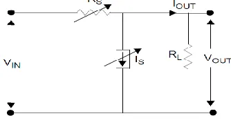
[image:3.612.84.251.398.490.2]The main idea behind a switch mode power supply can easily be understood from the conceptual explanation of a DC-to-DC converter, shown in below Fig 1. The RL load, needs to be absolute with a stable voltage, V-OUT, which is resulting from a main voltage source, V-IN. As shown in Fig 1, the output voltage V-OUT can be regulated by varying the series resistor (RS) or the shunt current (IS). When V-OUT is proscribed by unstable IS and observance RS constant, power loss inside the converter occurs. This type of converter is known as shunt-controlled controller. The power loss inside the converter is given by first Equation note that the power defeat cannot be remove even if IS becomes ideal.
FIGURE 1: DC-DC CONVERTER
Equation 1
Shunt-controlled regulator power loss
Equation 2
Series-controlled regulator power loss
This type of converter is known as a series - controlled controller. The zero power defeat in this converter depends on the value of the series conflict, RS, which is necessary to manage the output voltage, V-OUT, and the load current, I/OUT.
If the value of RS is either zero or infinite, the ideal power loss within the converter should be ideal. This feature of a series-controlled controller becomes the kernel idea of SMPS, where the renovation loss can be decrease, which consequences in make best use of competence. In SMPS, the series component, RS, is substitute by a semiconductor switch, which present very low resistance at the ON state, and very high conflict at the OFF state. A low-pass filter with non-dissipative reflexive components such as capacitors and inductors is placed behind the semiconductor switch, to make available steady DC output voltage. The semiconductor switches used to put into service switch mode power supplies are incessantly switched on and off at high frequencies, to convey electrical energy from the input to the output through the passive mechanism. The output voltage is controlled by unreliable the task cycle, frequency or stage of the semiconductor devices‘ transition phase. As the size of the passive components is inversely comparative to the switching frequency, a high exchange frequency results in lesser sizes for magnetic and capacitors. While the elevated frequency switching presents the expensive a giant advantage for growing the power mass, it adds power losses within the converter and introduce additional electrical noise.
What is a DC power grid?
―Power grids‖ is important for our discussion, but not necessarily simple. The DOE and the CEC jointly commissioned a report from Navigant Consulting in 2005 that wrestled with this extremely organization. The concluding description documented two ―Points of Universal Agreement‖ of what constitutes power grids, which remain valid today: A power grids consists of interconnected distributed energy resources capable of providing sufficient and continuous energy to a significant portion of internal load demand. A power grid possesses independent controls, and intended islanding obtain position with minimum service intermission (seamless transition from grid-parallel to islanded operation). These two definitions work easily in both the AC and DC domain, so we will borrow them both. DC power grids can be deployed in a portion of a building, building-wide or covering several buildings. We will refer to these systems (whatever their scale) as ―DC power grids‖ in the balance of this paper.
International Journal of Emerging Technology and Advanced Engineering
Website: www.ijetae.com (ISSN 2250-2459,ISO 9001:2008 Certified Journal, Volume 3, Issue 6, June 2013)
433
DC power is highly susceptible to impedance (or resistance) losses, which are those imposed by the transmission medium itself, usually wire. The nature of DC is such that resistance can quickly sap power, but the efficiencies of DC systems—as we shall see—are dramatic and must be considered in deciding the scale of a DC system. All of these grids have the common need to adopt standards to guarantee interoperability. These standards are essential to the efficient development of the grid and the successful achievement of the key goals of the Smart Grid at a lower cost than possible in the AC domain.
The national Smart Grid discussion should thus focus on ensuring that the grid optimally balances what we refer to as the ―Power Equation‖ (power generated, less line and conversion losses, equals power used). The present discussion focuses on DC power grids as a way to improve
the efficiency, reliability and security of the
implementation of the Smart Grid.
SELECTION OF SMPS TOPOLOGIES
Presently more than a few topologies frequently used to implement SMPS. Any topology can be through to work for any requirement; however, each topology has its own unique facial appearance, which makes it best suitable for a conV-INced request. To choose the most excellent topology for a given measurement, it is necessary to know the fundamental process, recompense, negative aspects, complication and the region of usage of a exacting topology. The subsequent aspect helps while choosing an suitable topology:
a) Higher or lower voltage output complete array of the input voltage?
b) How many essential outputs?
c) Is output from input dielectric separation required? d) Is the input/output voltage elevated?
e) Is the input/output current elevated?
f) What is the utmost voltage useful crossways the transformer major and what is the most responsibility cycle?
Factor (a) concludes whether the power provide topology should be buck, improve or buck-boost type.
Factors (b) and (c) decide whether or not the power.
BUCK CONVERTER
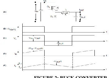
A buck converter, as its name entail, can only generate lesser typical output voltage than the input voltage. The essential graphic with the controlling waveforms of a buck converter is shown below Fig 2. In a buck converter, a switch (Q1) is placed in series with the input voltage spring V-IN. The input foundation V-IN provides for the output from side to side the exchange and a low-pass filter, realize with an inductor and a capacitor.
[image:4.612.330.506.348.474.2]In a stable condition of process, when the switch is ON for a phase of TON, the input supplying energy to the output as well as to the inductor (L). Throughout the TON stage, the inductor current stream during the switch and the distinction of voltages among V-IN and V-OUT is functional to the inductor in the advance direction, as shown in Fig 2 (C). Hence, the inductor present IL increase linearly from its in attendance worth IL1 to IL2, as shown in Fig 2 (E). Throughout the TOFF phase, when the switch is OFF, the inductor current keeps on to flow in the matching course, as the accumulate energy surrounded by the inductor carry on to supply the stack current. The diode D1 absolute the inductor current path all through the Q1 OFF stage (TOFF); thus, it is called a unrestrictive diode. Through this TOFF stage, the output voltage V-OUT is functional across the inductor in the overturn bearing, as shown in Fig 2 (C). Therefore, the inductor present decreases from its in attendance value IL2 to IL1, as shown in Fig 2 (E).
FIGURE 2: BUCK CONVERTER
(A) = Buck converter
(B) = Gate pulse of MOSFET Q1 (C) = Voltage across the Inductor L (D) = Input current IIN
(E) = Inductor current IL
SERIES RESONANT CONVERTER
International Journal of Emerging Technology and Advanced Engineering
Website: www.ijetae.com (ISSN 2250-2459,ISO 9001:2008 Certified Journal, Volume 3, Issue 6, June 2013)
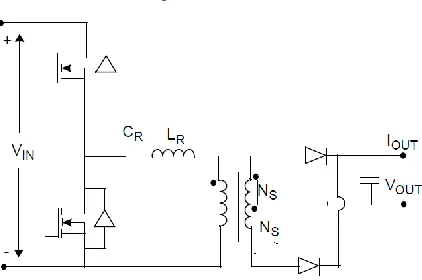
434 FIGURE 3: SERIES RESONANT CONVERTER
LLC Resonant Converter
In an LLC resonant converter, resonant tank elements (the inductor LR and the capacitor CR), are connected in series with the transformer primary, and the resonant inductor LM is connected in parallel with the transformer primary, as shown in Fig. The LLC resonant converter uses transformer magnetizing inductance for generating one more resonant frequency, which is much lower than the main resonant frequency comprising resonant tank LR and CR. The LLC resonant converter is designed to operate at a switching frequency higher than the resonant frequency of the resonant tank LR and CR. The benefit of the LLC resonant converter is narrow switching frequency range with light load and ZVS capability even at no load. In addition, its special DC gain characteristic, as shown in Fig, makes the LLC resonant converter an excellent choice for the front end DC-DC application. The first resonant frequency is determined by LR and CR and the other booming frequency is resolute by LR, CR and LM.
III. MEASURING COMPUTING POWER ACCURATELY
The prior section pointed out four common assumptions in measuring computing power which can lead to inaccurate results. The results from Powernet, however, represent only one point in time. As computing continues to evolve, green computing. Need to periodically re-measure energy consumption and waste. This raises the follow-up question: ‗Given limited time, money, and effort, how should one measure computing system energy consumption in order to minimize error? ‘ This section presents methodology considerations to guide future green computing research.
A. Characterization
Not all device classes are equal: some require much more effort to measure accurately than others.
Table IX, for example, showed a 43% variation in the power draw of Optiplex 760 PCs but a 0.01% variation in the power draw of HP 5400zl controllers. An estimated regulating of the poles apart devices in conditions of unevenness places desktops as the mainly diverse followed by servers, laptops, LCD monitors, and lastly, switches. Rather than distribute measurement points uniformly, one should measure the high variation device classes more densely. But device classes change quickly: Dell, for example, no longer sells Optiplex 760 PCs. Being able to determine which device classes have significant variation requires up-to-date, current measurements. To understand where to measure, one first needs to know which device classes is high variation and which are not. This can be done quickly, as a series of point measurements complete over a day. For example, assume that an endeavor has a large number of a new PC. One can randomly select 10 of these PCs and measure each of them booting. This will provide a large dynamic range of power measurements within the class as well as across the class. If the 10 show significant differences, then they might need to be measured densely. One can use the observed power draw distributions and statistically compute what deployment of sensors will lead to the lowest observed error. These point measurements should use simple digital readouts (e.g., Watt‘s Up or Kill-A-Watt meters) which a person reads and writes down. Depending on a wireless mesh or wired network ports is probably more trouble than it‘s worth.
B. Measurement
[image:5.612.63.274.116.256.2]International Journal of Emerging Technology and Advanced Engineering
Website: www.ijetae.com (ISSN 2250-2459,ISO 9001:2008 Certified Journal, Volume 3, Issue 6, June 2013)
435
[image:6.612.62.277.230.313.2]Concurrent work found that 10-second intervals are a reasonable choice, capturing power dynamics without overloading the infrastructure. Our familiarity illustrate that depending on the charge, different decision are desirable. For many practical uses – visualizing data, computing long-term estimates – even 5-minute averages are useful. Higher-resolution data is needed for correlating utilization metrics with power draw.
Figure 4. Power data collected once a second reveals a misbehaV-INg PC. Earlier, 5-minute averages hid the anomaly. In certain use cases it
is beneficial to have high-resolution data.
C. Extrapolation
The final step is to take the set of biased dimensions and extrapolate to whole system power. Our familiarities with Power net have decorated the need for data additional than power and consumption measurements. If extrapolation is to be successful, one also wants metadata in the form of equipment inventories and descriptions. Surprisingly, such metadata is not nearly as complete and readily available as we had hoped. Rather, we had to resort to indirect sources such as cross-correlating networked device registrations with active IPs on the network. In the future, green computing researchers should encourage IT personnel to keep updated and detailed records of what equipment is added to a building.
IV. CONCLUSION
Characterizing the energy use of organization computing systems is the first step toward identifying opportunities for improvement. Extensive, empirical data allow researchers to better quantify the problems they are tackling and the potential impact of their proposed solutions. Power net has provided such data and has shed light on some of the assumptions that we make when faced with the lack of solid measurements.
Despite our best attempts to cover as many computing systems for as long as possible, the Power net data remain but a single study. While the exact breakdown of energy use and waste might shift from building to building, the overarching methodology and data analysis lessons remain. Going forward, green computing research has not only a reference dataset to use but also a blueprint for how to characterize enterprise building power given limited time and resources.
The DC power grid concept represents a decentralization of the idea of the grid, and one that advances the goals of the current Smart Grid overhaul. The DC power grids begins to change the paradigm from a centralized generation and distribution system of power delivery to a system that is more flexible and more accommodating of the load that has come to be: one that is more electronic, more ubiquitous, and more essential to our economy and our culture. DC power grids can create power systems that are more efficient and more compatible with the fastest growing segment of the load today: electronic devices. In turn, by catering to the needs of digital devices, we naturally expand the networks in which they operate (both power and control) to benefit from – or indeed require – redundant operation that is primarily available today through the other ubiquitous DC device, the battery.
REFERENCES
[1] Maria Kazandjieva, Brandon Heller, Omprakash Gnawali, Philip Levis, and Christos Kozyrakis- Green Enterprise Computing Data: Assumptions and Realities, 978-1-4673-2154-9/12/$31.00 c 2012 IEEE.
[2] Mohammad Kamil, Microchip Technology Inc.– Switch Mode Power Supply (SMPS) Topologies, 2007 Microchip Technology Inc. [3] Paul Savage, Robert R. Nordhaus, and Sean P. Jamieson, Analyses written at the request of REIL, yale school of forestry & environmental studies
[4] Single Phase Multifunction Energy Metering IC with di/dt Input. [5] Department of Energy, Annual Energy Review, October 2011. [6] Energy Star Computer Power Data.
http://www.energystar.gov/index.cfm?c=