PROTOTYPE MODELING AND MATHEMATICAL APPROACH FOR THE EVALUATION AND MEASUREMENT OF A PARABOLIC TROUGH
REFLECTOR
MARK ANAK SELAT
A project report submitted in partial fulfillment of the requirement for the award of the degree
Master of Electrical Engineering
Faculty of Electrical and Electronic Engineering University Tun Hussein Onn Malaysia
ABSTRACT
ABSTRAK
CONTENTS
TITLE i
DECLARATION ii
DEDICATION iii
ACKNOLEDGEMENT iv
ABSTRACT v
ABSTRAK vi
TABLE OF CONTENTS vii
LIST OF FIGURES x
LIST OF TABLES xiii
LIST OF SYMBOLS AND ABBREVIATIONS xiv
CHAPTER 1 INTRODUCTION
1.1 Project Background 1
1.2 Problem Statement 3
1.3 Objective 4
1.4 Scope of Project 4
1.5 Thesis Outline 5
CHAPTER 2 LITERATURE REVIEW
2.1 Introduction 6
2.2 Review of Photovoltaic Energy 7 2.3 Concentrated Photovoltaic (CPV)
2.3.1 Solar Mirror Collectors 8
2.3.2 Optics 12
2.3.4 Reflection Slope Error 13
2.3.5 Solar Cells 13
2.3.6 Sun Tracking System 14
2.4 Previous work on parabolic trough evaluation 15
2.5 State of The Art of the CPV Technologies 16
CHAPTER 3 METHODOLOGY 3.1 The Evaluation of Parabolic Using Prototype Model 20 3.2 Reflection Angle of a Parabolic Reflector Surface 20
3.3 Slope Error of a Parabolic Reflector Surface 21 3.4 Mathematical description of the evaluation model 22
3.5 Setup of the prototype model 3.5.1 Materials 24 3.5.2 Prototype Setup 25
3.6 Experimental Works 26
CHAPTER 4 RESULT AND ANALYSIS 4.1 Introduction 33
4.2 Mathematical Formulation 34
4.3 Result of Parabolic Design and Building 36 4.4 Result of Experiment 39
4.5 Result of Focal Error Measurement 41
4.6 Result of Reflection Angle Measurement 42
4.7 Percentage Difference of Reflection Angle 45
4.8 Result of Slope Error Measurement 47
4.9 Summary of the Experimental Result 50
CHAPTER 5 CONCLUSION
5.1 Conclusion 52
REFERENCES 55 APPENDIX A: Value of axis x and p(x) for the equation of 57
parabola with focal length, f = 20 cm
APPENDIX B: Value of axis x and p(x) for the equation of 58
parabola with focal length, f = 12.5 cm
APPENDIX C: Result of Experiment using Parabolic Trough 59
with focal length 12.5 cm
APPENDIX D: Method of Measurement to Measure 60 Reflection Angle of Parabolic Trough
APPENDIX E: Illustration for the Proposed Design of the 61 Prototype Model
APPENDIX F: Illustration of the Prototype Model using 62 SolidWorks
APPENDIX G: Evolution of the efficiency of every 63 PV solar cells technologies (Source: NREL)
LIST OF FIGURES
1.1 Setup of one antenna method 2
2.1 A large solar mirror collector field located at 9 Kramer Junction California, USA
2.2 Schematic of solar trough collector 9
2.3 Parabolic and non-parabolic mirror cross section
(a) Reflecting mirror with ideal parabolic cross section 10 (b) Reflecting mirror with non-ideal parabolic cross section 10 2.4 Deforming a circular arc to a parabola by distributed
(a) Finite Element Analysis 11
(b) Resulting Applied Forces 11
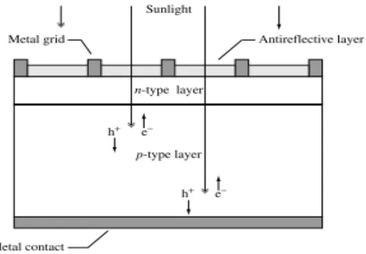
2.5 Schematic of a PV solar cell. The sunlight creates electron-hole 14 pairs, and respectively.
3.2 Graphical representation of a reflector surface slope error 22 3.3 Schematic design representation of the prototype model 25 3.4 Experimental prototype model to evaluate parabolic trough 26
3.5 Overall flowchart of the project 27
3.6 Image of reflected ray at the target 28
3.7 Strings represent the parameter of x 29 3.8 Illustration figure of the experiment parameter 30
3.9 Experimental process flowchart 32
4.1 Curve shape of the parabola for experiment 1(f=12.5) 36
4.2 Curve shape of the parabola for experiment 2(f= 20 cm) 36
4.3 Two different curve of parabolic trough use in Experiment 1 37
and Experiment 2
4.4 Real parabolic trough tested in Experiment 1 38 4.5 Real parabolic trough tested in Experiment 1 38
4.6 Definition of focal error, εd 41
4.7 Experimental result of focal error, εd for Experiment 1 and 2 42
4.8 Differences of reflection angle of rays between ideal case ( ), 43 measured ( ) and experimental ( ) for Experiment 1
4.9 Differences of reflection angle of rays between ideal case ( ), 44 measured ( ) and experimental ( ) for Experiment 2
4.10 Percentage difference of reflection angle for Experiment 1 46 4.11 Percentage difference of reflection angle for Experiment 2 47
4.12 Slope error plots for Experiment 1 48
LIST OF TABLES
4.1 Overall results for Experiment 1 40
CHAPTER 1
INTRODUCTION
1.1 Project Background
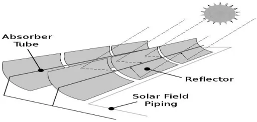
cell [4-7].One of the components of CPV is the reflector and one its famous type used as a solar reflector is the parabolic trough solar reflector .As we pursue efforts to lower the capital and installation costs of parabolic trough solar reflector, it is essential to maintain high optical performance. One of the main influences on the overall performance of a parabolic trough power plant is the optical quality of the concentrator field, which is determined by the reflectivity of the mirrors, the absorptivity of the receiver, and in particular the geometric precision of the reflector shape. Deviations from the optimum parabolic shape can lead to optical losses on account of reflected rays that pass the absorber tube. To check, qualify and improve existing collectors it is therefore important to have a tool that measures surface slope errors with adequate precision. Figure 1.1 below shows the illustration to define solar reflector and its components used in the CPV.
Figure 1.1: Parabolic trough reflector and components
1.2 Problem Statement
There is the trend toward urbanization and migration to cities in many developing countries such as our country, Malaysia itself, which is exerts increased pressure on the power grid and these forces governments to invest in the electric grid to meet growing demand. United Nations predicts world population will rise to more than 8 billion by 2013, which will lead to a global increase in electricity demand. The energy necessary to keep up with the demand cannot come only from fossil fuels, as they are reaching a limit in production, and they are one of the major causes for the rise in CO2 emissions, which is the number 1 believed cause for global warming. So, the solution is to turn to clean and renewable energy sources, capable of supplying large amounts of energy. PV industry needs to become affordable without government subsidies and incentives and be based on readily available, low cost materials. PV industry researchers searching for lower cost PV have investigated many CPV approaches. One of the popular design approaches for CPV is the parabolic solar collectors and so as we pursue efforts to lower the capital and installation costs of parabolic trough solar collectors, it is essential to maintain high optical performance.
1.3 Objectives
The aim of this project is to evaluate solar parabolic trough reflector for concentrated photovoltaic system using numerical modeling and experimental approach. The others are as follows:
i. To construct a functioning prototype model base on mathematical modeling technique to evaluate errors and optical profile of a parabolic reflector.
ii. Propose a measurement technique and procedure in evaluating solar parabolic trough reflector using simple measurement setup and tools.
iii. To analyze the errors and performance of the designed solar reflector using the proposed experimental procedure and mathematical approach.
1.4 Scope of Project
This project implementation generally comprises a study and research through experimental and development evaluation. It needs to be appropriate with the aspects of solar parabolic trough (reflector) in a concentrated photovoltaic. The scope particularly is:
i. Building a functional prototype model to evaluate solar parabolic trough reflector with the size limit of reflector up to 20 cm square.
iii. Analyzed the parameters value obtained from the experiment by three different condition; ideal (consider zero error), actual and measurement (using protractor).
1.5 Thesis Outline
CHAPTER 2
LITERATURE REVIEW
2.1 Introduction
Literature review is a study about the project and this chapter covers the fundamental concepts of Concentrated Photovoltaic (CPV) and the fundamentals of optics applied to concentration.
It involves all the aspect which can be linked to the project or research which is available in outside world. The research is not mainly focus directly to research which is already performed but also focused on fact research and references of studies. The source and information can be available from internet, library, and also from a person who has high knowledge about the research. This research is important because it resemble the starting point to creating, upgrade and producing a quality research which have trustable result obtained.
2.2 Review of photovoltaic energy
A definition of a photovoltaic (PV) system is a system that converts directly solar radiation into electricity [4]. Since it was first found, in 1839 by Edmond Becquerel, and after improvements made in the almost 100 following years, the photovoltaic energy has raised a constantly growing interest all over the world. The possibility to generate electrical energy in practically any place in the world was extremely appealing. With the major drawback of the high cost of solar cells, the almost exclusive use of PV energy was made by space industry to fuel satellites, where no budget constraints were applied. The efficiency of solar cells more than double from 6% in 1954 to 13.5% [8], but still too expensive. Today the top efficiency of silicon cells is around 27.6% 2.2
Ironically, it was in offshore oilrigs and isolated on-shore gas and oil fields, among others, where PV systems were used, replacing the toxic and short-lived batteries [5]. Nowadays, total PV installed capacity is estimated to reach 50.9 GWp, representing a growth of 62.1% comparing to 2010 [8]. The continuously increasing price of oil, the global warming, the Kyoto Protocol, and the recent nuclear disaster that occurred in Fukushima, Japan, turns the attention of the world to renewable energies [4].
2.3 Concentrated photovoltaic (CPV)
Suns); medium (up to around 150 Suns); high (higher than 200 Suns) [11]. Small concentrations try to ally the advantages of conventional PV models (high acceptance angle) with the advantage of CPV (lower costs related to solar cells, higher efficiency) [6]. Higher levels of concentration drastically reduce the solar cell area (sometimes to a few square millimeters) but usually require high efficiency solar cells (which are expensive),a very high sun tracking precision, and usually require active cooling systems, as the efficiency of solar cells, decrease with increasing temperatures.
Medium concentration was the most popular choice as it combines the best features of both low and high concentration. With the recent entering in conventional PV market by Chinese companies, which build cheaper PV modules, and the advent of thin-film PV cells, the PV modules price dropped significantly. These factors decrease the main advantage that CPV systems had over conventional PV that is the price reduction. This fact will force the CPV market to increase the concentration to much higher values [12]. A CPV system is mainly formed by three different components which are optics, solar cells, and the sun tracking system.
2.3.1 Solar mirror collectors
Solar mirror collectors are a major subsystem of many solar energy systems, particularly for solar thermal generators [13]. Large thermal systems may use many collectors covering large sites as shown in Figure 2.1. Collectors generally consist of concentrating parabolic mirrors, an absorber tube and a supporting structure, which is often equipped with a solar tacking mechanism. They are called parabolic trough collectors (PTCs) [14], see Figure 2.2.
Figure 2.1: A large solar mirror collector field located at Kramer Junction
California, USA [14].
Figure 2.2: Schematic of solar trough collector [15].
[image:18.612.180.436.271.393.2](a) Reflecting Mirror with Ideal Parabolic Cross Section
(b) Reflecting Mirror with Non-ideal Cross Section (Circular) Figure 2.3: Parabolic and Non-parabolic Mirror Cross Section.
[image:19.612.177.437.75.235.2]Distributed forces to form parabolas from simple circular shapes also have ever been used. Figure 2.5 shows a set of distributed forces that will make an easily made a circular mirror into approximately parabolic shape. Figure 2.4 (a) shows the shape adjustment required to forming a parabola from a rolled circular sheet material. Figure 2.4 (b) shows an example of the required forces when 11 distributed forces are applied. While this approach can achieve the desired result, it requires far more forces than the 11 shown to achieve a smooth parabolic shape, and the implementation of the applied forces in the real system is very complex. A complete discussion of this work is beyond the scope of this paper, and the reader is referred to [16] for further details. Hence a new approach that is simpler to implement is presented in this paper.
`
(a) Finite Element Analysis
[image:20.612.181.468.305.680.2]
(b) Resulting Applied Forces (in N)
2.3.2 Optics
CPV system use reflective and/or refractive materials, mirrors or lenses, to concentrate the light. The most common lenses used are Fresnel lenses, either point-focus or linear focus, depending on the type of focus shape that each one forms. The material chosen to manufacture the lenses is usually PMMA, an acrylic plastic with special characteristics. It is molded relatively easy where it has good weather ability, important to guarantee a large warranty of the module (usually up to 15-20 years).
A factor that decreases the long-term durability of the lenses is the fact that they tend to gain a yellow color, result of the effect of ultraviolet radiation that deteriorates the PMMA [17]. Some tests have been done to produce lenses using glass, but so far, they have not been successful [18].Alternatively to lenses, are mirrors, which instead of refracting the light, it reflect it. Made of aluminum or a special reflective coating, mirrors can have different shapes and have a large longevity as the aluminum does not deteriorate and can even be recycled. The most common shapes are the parabolic mirrors, that concentrate light parallel to their axis in one point, or parabolic troughs that form a focus line.
2.3.3 Fundamentals of Optics Applied to Solar Concentration
The theory of optics is usually associated with the creation of an image from an initial object. Therefore, in imaging optical systems the light emitted by a point in the object, is captured by the optical system and is concentrated onto a specific point in the image, in order to the image be proportional to the object [17]. In CPV systems, it is not necessary to form an image of the Sun in the receiver, as the main goal is to transfer the maximum energy from a source into a receiver.
2.3.4 Reflector Slope Errors
It was first recognized in 1981 by Wood that a great deal of information could be ascertained by analyzing the reflection of the absorber tube in parabolic trough collectors [19]. Just as parallel rays from the sun are reflected off a parabolic trough onto the absorber, so are the lines of sight from an observer reflected onto the absorber tube. Thus an observer aligned with the optical axis of the collector sees the reverse, an enlarged image of the absorber on the reflective surface. Wood’s method utilizes the shape of this reflected image to ascertain detailed information about the optical performance of the collector. The German Aerospace Center (DLR) has successfully implemented a quantitative variation of Wood’s method to measure slope errors of parabolic troughs from the reflected absorber image [20]. The method uses high-resolution digital photography. A series of photographs is taken of the collector from either the ground or a radio controlled helicopter (second publication). In the original paper, the absorber location and camera position on the ground are measured with a laser distance meter.
Most recently, the camera position in the air is determined using photogrammetric resection based on a series of ground control targets placed around the collector. The authors do not disclose their method for measuring the absorber position for the airborne technique. In all of these techniques, the uncertainty in the reflector slope errors depends on the uncertainty in the absorber location measurement. In each case, the absorber location is measured independently and then used along with images of the reflection of the absorber to find the reflector slope errors.
2.3.5 Solar cells
increasing the amount of light that reaches the silicon. Usually located right under this layer, is the metal grid that with the bottom contact, form the electrical contacts to where the current carriers will pass.
[image:23.612.178.443.260.444.2]The silicon is divided to form two layers: one n-type, thinner and negatively doped with phosphorus, and the other p-type, thicker and positively doped with boron [7]. Several types of PV cells exist, depending on the semiconductor used. The most common is the silicon, but even using just silicon, there are different configurations.
Figure 2.5: Schematic of a PV solar cell. The sunlight creates electron-hole pairs, and respectively.
2.3.6 Sun Tracking System
Usually in low concentration levels, only tracking in 1 axis is required, while in medium to high concentration, 2-axis trackers are used. Trackers are an extra cost in CPV systems compared to conventional PV modules, being the price proportional to the tracking precision (usually measured in degrees). The tracking precision necessary is imposed by the acceptance angle, which is the tolerance that the optical system have to a deviation in the angle of sunlight rays [10].
2.4 Previous work on parabolic trough evaluation
One of the methods to evaluate solar parabolic trough performance is by using the finite element modeling and ray tracing by Joshua M. Christian et al [9]. In this paper the finite-element models were used to determine the impact of gravity loads on displacements and rotations of the facet surfaces, resulting in slope error distributions across the reflective surfaces. The geometry of the parabolic trough collector was modeled in SolidWorks, and the effects of gravity on the reflective surfaces are analyzed using SolidWorks Simulation. The optical performance of the deformed shape of the collector (in both positions) is analyzed with additional induced slope errors ranging from zero up to 1° (17.44 mrad). The intercept factor for different solar incident angles found from ray-tracing is then compared to empirical data to demonstrate if the simulations provide consistent answers with experimental data.
2.5 State of the art of concentrated photovoltaic technologies
Despite increasing market of PV systems, there are just 28 MW of CPV capacity installed, out of more than 33000 MW of PV installed capacity [21]. Low penetration in the market is mainly related to the areas that where the market increased, were developing countries, where CPV systems are not that advantageous as they require more maintenance, comparing to conventional PV modules. Despite these facts, future perspective is of growth for CPV systems. Actually, there are around 689 MW of new CPV capacity under construction, that may increase with potential large scale projects to be constructed India and South Africa [22].
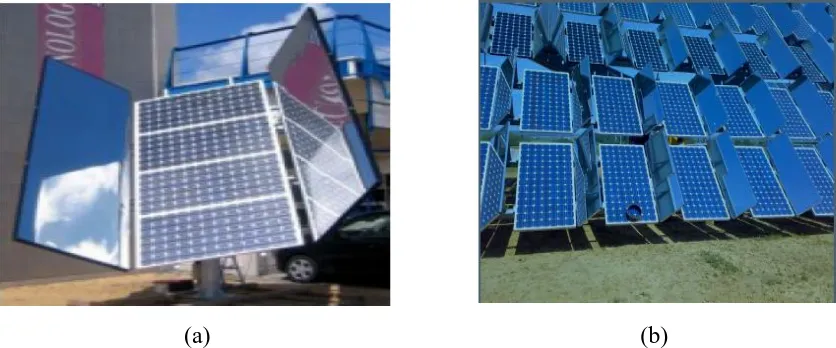
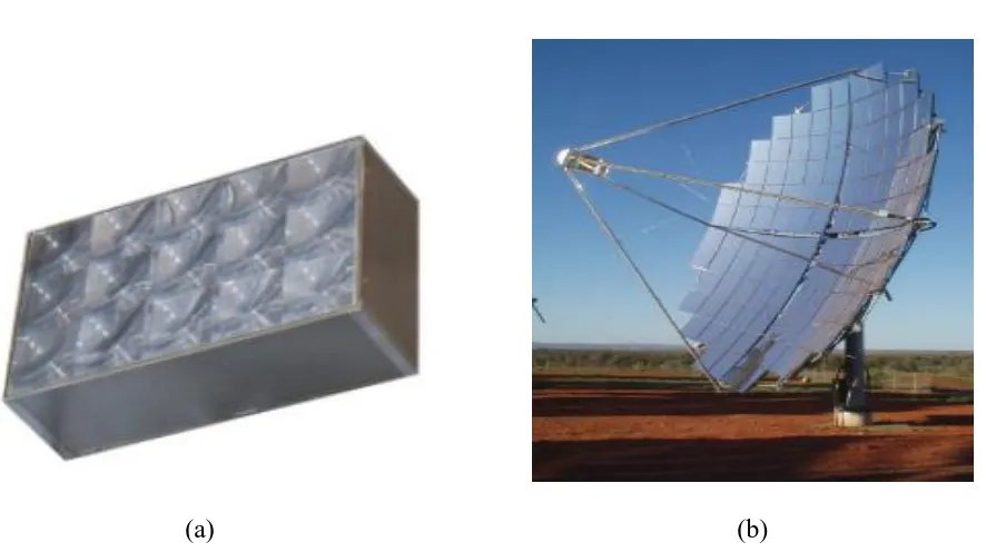
In Figure 2.6, low concentration CPV systems are presented. Both systems, either Double Sun from WS Energia or the one from Zytech, use mirrors to concentrate light into a conventional PV system. Two medium CPV systems are shown in Figure 2.7. The first system, HSUN, from WS Energia, uses parabolic trough mirrors to concentrate light into PV cells located in the back of the next parabolic trough. The second system, from Zytech, uses prismatic lenses to concentrate the sunlight. Figure 2.8 shows two high concentration CPV systems. The first system, from Emcore, uses point-focus Fresnel lenses, while the second concentrator uses parabolic dishes mirrors to concentrate in a single PV cell, while the previous seen systems use smaller modules.
[image:25.612.112.530.500.674.2]
(a) (b)
(a) (b)
Figure 2.7: a) Medium concentration (20 Suns) HSUN, from W.S. Energia. b) Medium concentration (120 Suns) from Zytech
(a) (b)
[image:26.612.114.536.71.273.2] [image:26.612.90.533.358.606.2]CHAPTER 3
METHODOLOGY
This chapter presents the general working flow of the project, which also discuss in detail the mathematical modeling to be implemented and the experimental model developed to evaluate parabolic troughs together with the details of its experimental works. As what we discussed in the previous chapter, parabolic trough is the optical element that most losses can inflict, within reasonable values. The errors in the contour, especially those where parts of the parabola are rectilinear, can make the total incident power drop drastically. To be able to evaluate and measure quantitatively those errors, an experimental model to evaluate parabolic troughs was developed. This evaluation model had to satisfy these three objectives:
1. Measure the optical parameter profile of the parabolic trough by experimental analysis which is to be synchronized and compare with the mathematical modeling
2. Measure the reflection angle along the surface of the parabolic trough.
3.1 The Evaluation of Parabolic Using Prototype Model
The parabolic evaluation model consists in a mathematical model that is able to measure the errors of slope along a section in a parabolic trough. The laser light scanning the parabola trough will forms a section that has a form of a parabola. To ease the description, in this chapter the line drawn by the laser scanning along the parabolic trough is referred as a parabola. The prototype was built at this period of time later to experimentally apply the model to real parabolic troughs. To begin the model, it was defined that, to evaluate a parabolic trough, it was divided into several parabolas, and then each one of those parabolas was individually studied. Then, it is possible to evaluate a parabolic trough in different sections.
This study is particularly important because of the manufactured structure used to support the parabolic trough. As it has only two supports, located in the ends, the contour of the parabolic trough have different characteristics and defects, depending on the position analyzed. As seen in the prototype, the primary mirror has a more perfect curvature where is supported than in the middle section.
3.2 Reflection Angle of a Parabolic Reflector Surface
from the laser pointer with ray which is reflected through the focal point of the collector where in this project, opaque glass as a target is assume as a collector.
Figure 3.1: Graphical representation of a reflector surface reflection angle
3.3 Slope Error of a Parabolic Reflector Surface
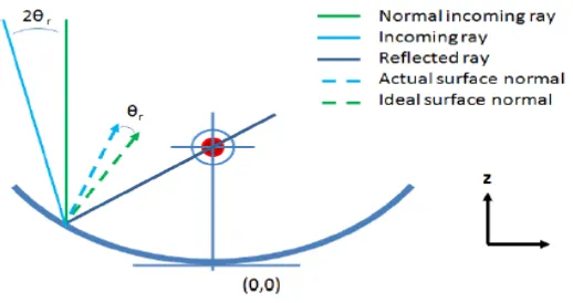
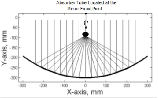
Slope error of a parabolic trough must be modeled as a distribution of reflection angle in order to combine the effects of reflector slope. For a perfect reflector with no surface slope errors, an incoming ray, assumed to be parallel to the optical axis, will be reflected and pass through the focal point of the parabola as shown in Figure 3.2 (labeled as “ideal reflection”). For an incoming ray to pass through the center of an absorber that is not aligned with the focal point, the reflector surface must have non-zero slope error or by means that the incoming ray from the laser pointer is reflected at a point other than the focus point. An absorber misalignment or indicate as focal error in this project can thus be modeled as a perfectly aligned absorber and a set of effective slope errors in the reflector surface.
Figure 3.2: Graphical representation of a reflector surface slope error
3.4 Mathematical description of the evaluation model
The principle of the model is that an incident ray of light, parallel to the axis of a parabola, will be reflected to the focus of that parabola. If the parabola has some sort of defect in the surface, the ray will be reflected to a point, other than the focus. Knowing that the refection angle ( ) of a ray of light is changed by a surface with an inclination, by the following equation:
= + 2 X α , (3.1)
if a reflected ray has a certain angle deviation, ∆ ,from the theoretical ray that pass through the focus, the error in slope of the point in the parabola where the ray was reflected, is given by
=
(3.2)
Considering a ray reflected in a point in a parabola, with coordinates (x,p(x)), where x the abscissa measured from the focus, and p(x) is the equation of the parabola. The incidence point in the target has coordinates (0,d), where d is the measured distance from focus to the incidence point. The reflection angle of a ray is given by
(x,d) = ArcTan ( ) (3.3)
Substituting equation 3.2 in equation 3.3 and substituting for the incident point and the focus, the slope error of the reflection point of the parabola mirror is given by
=
ArcTan ( ) - ArcTan ( )2 (3.4)
With the model presented, it is possible to evaluate a surface of a parabola, point-by-point, using equation 3.4, in which the variables are obtained by measuring the distance from the incidence point in the target to the focus and the reflection point in the parabola.
3.5 Setup of the prototype model
3.5.1 Materials
To build the experimental model prototype to evaluate parabolic troughs, it used the main following materials:
1. Laser pointer
As it is only necessary a visible light source that creates a small spot in the mirror, and no lenses or refractive material is used, a common laser pointer is sufficient to this study.
2. Opaque glass
The rectangular piece of opaque glass was used as target. The function of the target is to intercept the light in the focus vertical plan, but has to let some light pass in order to the camera to capture it or visible to the experimenter to observe it, hence the opaque glass. A regular glass can’t be used as a target, since it will cause second reflection to the parabola and back to the target. This fact may not be seen with the use of opaque glass.
3. Aluminum tubes
Due to the relative low density and large amount of aluminum tubes available around UTHM, Parit Raja area, it was the preferred material to build the overall structure.
4. Aluminum mirror
REFERENCES
1. Bhubaneswari Parida, S. Iniyan and Ranko Goic (2011) . Review of Solar Photovoltaic Technologies. Renewable and Sustainable Energy Reviews 15,pp. 1625–1636.
2. Alasdair Cameron.Tracking the CPV Global Market. Renewable Energy World Magazine. August edition.2011. pp 60-72.
3. D. Mills and R.Morgan. Solar Thermal Power as the Plausible Basis of Grid Supply.2008. Bayshore Rd, USA. pp (30 -36).
4. Andreev VM. and Grilikhes VA.Photovoltaic Conversion of Concentrated Sunlight. John Wiley and Sons Ltd.1997.England.pp 185 -259.
5. J. Perlin.History of Photovoltaics. 2005.9(2) pp 104 -116.
6. W. Weisner (2005). Modeling of PV Modues-Efect of Non-Uniform Irradiance Performance Measurements with Solar simulators. Proc of 16th European PV Solar Energy Conf. Glasgow.pp 18-92.
7. A. Luque, S. Hegedus. Handbook of Photovoltaic Science and Engineering, Wiley. pp 88-93.
8. Mendes Lopes .J,et al. On field Demonstration Results of Medium Concentraton System, HSUN. Proc of 7th Int. Conf. on Concentrating Photovoltaic Systems, Kas Vegas,USA.2011.pp 5-19.
9. Joshua. M (2011). Finite Element Modeling and Ray Tracing of Parabolic Trough Collectors for Evaluation of Optimal Intercept Factors with Gravity Loading. Proc of the ASME 2011 5th Int. Conf. on Energy Sustainability. pp 2-9.
11. Mendes Lopes. Method for Analysis, Optimization and Design of Optics for Photovoltaic Concentration”, Institute Superior Technical, University Technical of Lisbon, 2010.
12.J. Chaves. Optical Science and Engineering.1st edition, CRC Press Chapter 1.2004.pp 33-45.
13.Romeo .M and Martinez.(2004). Terrestrial Solar Thermal Power Plants : On the Verge of Commercialization. Proc of the 4th Int. Conf. on Solar Power from Space. Granada. pp 81-89.
14.Google (2013). Google search – Retrieved on September 20,2013, from http://www.powerfromthesun.net/chapter2.htm.
15.Wikinet (2013). Wikimedia Search – Retrieved on September 21 , 2013 , from http://commons.wikimedia .org/wiki/file:parabolic_trough.svg.
16.Hatwambo S,Hakansson, and H. J. Nilson.(2008_.Solar Energy Materials and Cells.2008.92(11). Pp. -1347 -1351.
17.Alasdair Cameron (2011) Tracking The Market:Focus on the Concentration Photovoltaics Sector. Renewable Energy World Magazine, Penn Well, July – August 2011.4(14).pp 301-323.
18.R. Winstom, J. Minano and Benitez. Non-imaging Optics. Elsevier Academic Press.2005.pp.93-105.
19.Wood R. Distant Observer Techniques for Verification of solar Concentrator Optical Geometry. Technical Report, Lawrence Livermore National Laboratory, 1981.
20.Prahl C and Roger M.(2011). Airborne Shape Measurement of Parabolic Trough Collector Fields. Proc of the 17th SolarPACES Int. Symposium. Granada. pp 117-141. 21. Y. S. Hong, T. C. Chang.(2010) A Comprehensive Review of Tolerancing Research,
International Journal of Production Research.2010.1 (3) :22- 25.

![Figure 2.4: Deforming a circular arc to a parabola by distributed forces [16].](https://thumb-us.123doks.com/thumbv2/123dok_us/8772134.899458/20.612.181.468.305.680/figure-deforming-circular-arc-parabola-distributed-forces.webp)