sis κ· r aiiíss ; B A T ™ ! r a w *
AWE«
wÆWmim^mm^
mmw
4 53 6 e ϋ
κ
lÉlilÊ
MW
¡•Mitt «
SJ II
W » l
»CÜ
GEOMETRY ROUTINES
1!
FOR USE IN THE TIMOC CODE
jxilJjjäC«
1 u 'W:
K'P.»
R.J. JAARSMA and H. KSCHWENDT
u
'
" m m
Am
W B Ç f
¡MIM
ili»
1
h.'«ii
"ill
!p
f i l l i
iài
βί.Τ#Ην·.6ι·' ''ti ¥'·}*·irrt*'Tit··* u It- i i iS i l l
β
*l· »íí***
1970
,β
¡ft!»
iiliiipifl
" f f i f l
Itófti
jÉIÏ
Ä h ; · Ispra Establishment - Italy
Reactor Physics Department Reactor Theory and Analysis
• 1 ¿'{«"riiiií-tB
Jip
Joint Nuclear Research Centre
J i l l
t'.'fiL'HI·
- ■ : :
Itctif
ïSiMiï
LH! fi* ifjfjtkr**
ras
J.OMI
mr
mËmÊSÊÉËM
lS»iiifô:$lSi^Sa:
.ïïlL'i'r^èi·*''! ¡8fL.
if
¡wm m
» f ifiWiiilííi
This document was prepared under the sponsorship of the Commission of the European Communities.
Neither the Commission of the European Communities, its contractors nor any person acting on their behalf
make any warranty or representation, express or implied, with respect
io t h e accuracy, completeness, or usefulness of the information con-tained in this document, or that the use of any information, apparatus,
i
'ΐΙΐΙιΡβίΐΙΙΙιΙΐιΙ
mèi ìfimifc
lili
β'Ι*!?8ΚίΜΙ"Ρ
lite
ÌMrEGAL NOTICE
(■Hi'iuriH'i
method or process
'Sfili! iHMriïïli Tiilft"! 'VH* I'''"*·™'
[«lía to
eport is on sale a t t h e addresses listed on cover page 4
Λ
DM 7.30 It. Lire 1 250 Fl. 7.25
*®
When o r d e r i n g , p l e a s e q u o t e t h e E U R n u m b e r a n d t h e title, w h i c h a r e indicated o n t h e cover of e a c h report.
Printed b y Guyot, s.a., Brussels Luxembourg, December 1970
¡ i l l
, December 1970
This document was reproduced on t h e basis of t h e best available copy
¡ 1 É ·
EUR 4536 e
G E O M E T R Y R O U T I N E S F O R U S E I N T H E TIMOC CODE by R J . JAARSMA and H. K S C H W E N D T
Commission of the European Communities
Joint Nuclear Research Centre - Ispra Establishment (Italy) Reactor Physics D e p a r t m e n t - Reactor Theory and Analysis Luxembourg, December 1970 - 72 Pages - 20 Figures - B. Fr. 100.—
For application in the Monte Carlo Code TIMOC a number of subroutines describing different geometrical configurations have been developed. Their description is collected in this report. The first three subroutines of this report were made a long time ago for special purposes and describe such simple geometries as cylinders, slabs and spheres, as well as more complicated con-figurations like concentric rings, ring sectors, lattices of cylinders or spheres. A complete description of the problems which can be handled, the way of linking to the main programme and the preparation of the input d a t a are given. The last article in this report deals with the adaptation of the subroutine GEOM of the 0 5 R code, a more general geometry subroutine, to the TIMOC code.
EUR 4536 e
G E O M E T R Y R O U T I N E S F O R U S E I N T H E TIMOC CODE b y R . J . JAARSMA and H. K S C H W E N D T
Commission of the European Communities
Joint Nuclear Research Centre - Ispra Establishment (Italy) Reactor Physics D e p a r t m e n t - Reactor Theory and Analysis Luxembourg, December 1970 - 72 Pages - 20 Figures - B. Fr. 100.
Only the way of linking has been explained, other information must be taken from the 05R report.
E U R 4 5 3 6 e
COMMISSION OF THE EUROPEAN COMMUNITIES
GEOMETRY ROUTINES
FOR USE IN THE TIMOC CODE
by
R.J. JAARSMA and H. KSCHWENDT
1970
Joint Nuclear Research Centre Ispra Establishment - Italy
A B S T R A C T
For application in the Monte Carlo Code TIMOC a number of subroutines describing different geometrical configurations have been developed. Their description is collected in this report. The first three subroutines of this report were made a long time ago for special purposes and describe such simple geometries as cylinders, slabs and spheres, as well as more complicated con-figurations like concentric rings, ring sectors, lattices of cylinders or spheres. A complete description of the problems which can be handled, the way of linking to the main programme and the preparation of the input data are given. The last article in this report deals with the adaptation of the subroutine GEOM of the 0 5 R code, a more general geometry subroutine, to the TIMOC code. Only the way of linking has been explained, other information must be taken from the 0 5 R report.
KEYWORDS
GEOMETRY SPHERES MATHEMATICS LATTICES MONTE CARLO METHOD RESEARCH REACTORS
Table of Contents
Page
Introduction 5
SORSEC
Summary 7 1„ Geometry 8 2. Calculations 10 3. Communication with the RWS programme 11
4. Remarks and Explanations 12
5. Entries 14 6. Input 16
Figure 1 21 Figure 2 22 Figures 3, 4 and 5 23
Appendix 1 Example 24 Appendix 2 Algorithmics and flow charts 27
Appendix 3 Algorithmics of starting points 38
GSPHER
40
41
1. Summary 2. General
3. Communications with the RWS programme 41
4. Entries 43 5. Input 44
Figure 1 4^
SLBCYL
Summary 47 1. Geometry 48 2. Calculation 48 3. Communication with the RWS program 48
4
-GEOM (05R) 1. Summary
2. General View 2.1 Method
2.2 Restrictions
2.3 SMEC (Small Effect Calculations) 2.4 Start routine
3. Input 4. Deck Setup 5. Map of Common
6. Modifications of the RWS Programme 7. Programme Descriptions
GPATH PATH1 STARTN RNFLS
ENTRY: GPRNT GSTRT CELL SURFC PROJ NAME GINP GEPR GERJ GEDS GMAC WRTP
BVTBF GREAD RSTRT
56
57
57
58
58
58
59
60
62
64
68
68
69
70
70
71
71
71
71
70
5
-GEOMETRY ROUTINES FOR USE IN THE TIMOC CODE *)
Introduction
The geometry routines used by the Monte Carlo Code TIMOC have more or less an independent character. The descriptions made of them are collec-ted in this report under the following titles:
SORSEC (R.J. Jaarsma) - Describes a cylindrical system and has been de-veloped to simulate the proposed Euratom pulsed fast reactor SORA.
GSPHER (H. Kschwendt) - Describes a system of concentric spheres.
SLBCYL (R.J. Jaarsma) - Describes a system of infinite slabs or a system of infinite concentric cylinders in a rectangular lattice.
GEOM (R.J. Jaarsma) - Describes the adaptation of the 05R-GE0M routine for the use in the TIMOC code.
This report contains 3 independent routines. The summary in the beginning of the description of each routine gives in short moreinformation.
For each of the routines an exposition of the problems it may deal with and a user's manual is given. The most extensive description is given of SORSEC, sometimes a reference has been made to this in the description of the other routines. In this report the parameters are named with the names used in the programs. As the routines have been developed separately
from each other, the same parameters may sometimes not have the same name in the different routines, while it also may happen that a name is not covering the same parameter in each routine. However all parameters are defined explicitly in each of the three descriptions.
The routines are written in the FAP language for the IBM 7090 computer. They were tested carefully and used many times in practice for different configurations.
- 6
7
-SORSEC - A Geometry Routine for SORA Type Reactors
R.J. Jaarsma Summary
The geometry routine, described here, has been designed in order to make possible the application of the Monte Carlo Method to a very detailed model of the proposed Euratom fast pulsed reactor SORA. The first version
1)
of the routine was made by W. MATTHES . It has been improved and developed into the present version by the author.
The main feature of the geometry routine is that it calculates, for a neutron with a given starting point, direction and flight path,a collision or crossing point in a 3-dimensional configuration. By crossing point is meant the point at which the neutron enters another geometrical region of the assembly. The basic assembly consists of one or more concentric cyl-inders, each of which can be cut, if required, into several rings. These rings can be subdivided yet further into sectors, giving, when necessary, a very detailed heterogeneity.
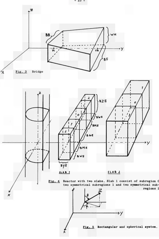
In addition this cylindrical assembly can be truncated by a plane parallel to the axis of the cylinders, the resulting secant plane being termed "the window". In combination with this window, a special prisma, called "the bridge", may be inserted in such a way that the rectangular ground or upper plane is in the window and the rest of the bridge is surrounded by the parts of the cylinders. Fig. 2 and 3 make this clear. In front of the window one may put one or two slabs, with the planes parallel to the axes of the coordinate system, each consisting of 1, 3 or 5 symmetrical parts (fig. 4 ) .
The programme can be made to select different combinations of the above
geometries, according to needs of a particular problem, by varying ap-propriate parameters. The above geometrical options were concieved with
special reference to the SORA reactor.
The calculation times associated with the programme (which is written in FAP for the IBM 7090 computer) have been minimized as much as possible at
present.
1)
1) Geometry
The rectangular coordinate system is defined so that the axis of the con-centric cylinders is the z-axis and, if there is a window, the front plane of this is parallel to the z-axis and normal to the y-axis; the positive y-axis goes through the center of the window and bridge.
The geometrical regions are defined in the following way: The cylinders by their radii; the planes, which cut the cylindrical shells in rings, by their z-coordinates; the sector walls in a ring by the anticlockwise angle with the positive y-axis; the window by the y-coordinate; the bridge by the y-coordinate of the back plane, width of the front and back plane and height; the slabs by their center and dimensions (the planes of the slabs are assumed to be parallel to the axes of the cylindrical system).
The cylindrical system (inclusive of the bridge, if there is one) and slab 1 and 2 may not touch each other i.e. all three must be separated by gaps. The y-coordinates of all parts of slab 2 must be greater than the y-coor-dinates of all parts of slab 1. The bridge may not project outside the out-most cylinder. Allowance is made for the free leakage of neutrons at the
9
-The geometrical regions are identified in the following way:
Main region:
Shells from inside to outside are numbered 1 to M. The "space" is taken as main region M+l (= L ) . The bridge is main region L+l.
Slab 1 (nearest to the window) is main region L+2. Slab 2 is main region L+3.
Subregions:
a) In the shells subregion O is the part above and below the cylindrical regions. It extends to infinity in both directions. The rings are numbered from the bottom to the top by 1,2,...
Note: The number of rings is equal in each shell and is therefore defined by the shell with the most rings. Therefore one has to add dummy rings of zero hight in those shells, which contain less rings. These dummy rings must be at the bottom.
b) In the slabs subregion 0 is the center part. Subregions 1 are the two symmetrical parts on both sides of subregion 0, subregions 2 the next two symmetrical parts. The symmetry is with respect to the plane of the system parallel to the y-z plane through the center of the slab.
Sector regions :
They exist only in the rings. Starting on the positive y-axis and going in the anticlockwise direction, they are numbered 1,2, etc. The sector part between the last sector and the positive y-axis belongs automati-cally to sector 1.
Limits:
- l o
in the BCD-deck and making a new assembly. The number of cylinders and sectors is only limited by the storage available in the computer.
Error messages ;
In consequence of rounding errors, it may happen that when the flight path of a neutron exactly or nearly intersects with the z-axis of the system, the square of the distance of these two lines becomes negative. This square is an intermediate result. In such a case the square of the distances is set equal O and a message mentioning the negative value is printed.
Another consequence of inaccuracy is that sporadically the x, y, ζ coor dinates are not consistent with the geometrical region parameters. In such a case the neutron becomes lost by leakage (RGM = 0) and the following mes sage will be printed:
EXTC. Z = ·»·, Y = ·.., X = ···, AKu = .·., RG = ...
2) Calculations
The central part of the geometry programme is the routine with the entry GPATH . This part calculates the crossing point with the boundary of the actual geometrical region or a collision point in this region. The dis tance S to the boundary (in cm) along the flight path of the neutron is always calculated (see appendix 2). By Λ we denote the random variable
to select the neutron flight path between collisions ζ λ = number of mean
free paths between 2 collisions). If S is equal to or less than the flight
path, Λ/Σ"«» t n e neutron is assumed to leave the region, the crossing
point is calculated and the number of mean free paths, λ, is decreased by S-Z^ . Otherwise a collision occurs before the boundary, the length of the flight path is λ / Σ * and the collision point is calculated. The part of the routine with the entry GSTRT calculates random starting points in indicated geometrical zones (see appendix 3 ) .
11
3) Communication with the RWS main programme
A set of parameters, whose values at any time suffice to completely
characterize the neutron, is stored in the COMMON part, with the
following notation (I = integer, F = floating point number):
RGM:
RG:
ARG:
X:
Y:
Ζ:
.Material number (in TIMOC called region index) in the actual geom. region. (I)
Geometrical main region number. (1)
Geometrical subregion number. (I)
Rectangular space coordinates, giving position of the neutron. (F)
SINP:
CØSP:
SINT:
CØST:
SGT:
MFP:
FPATH:
PTHX:
Defining f and Θ, being the spherical coordinates for
the direction vector (Fig. 5 ) . (F)
Total crosssection of material RGM. (F)
Number of mean free paths in the flight path of the neutron. (F)
Length of flight path to next collision point in cm. (F)
Length of flight path to a crossing point in cm. (F)
NRG: No meaning.
QRET:
QØUT:
SEKN:
BLR:
QSTPT:
QTIME:
QCØLL:
QBLØC:
Used for special feature. See explanations.
Special parameters. See explanations.
If Φ 0, fixed start point of primary neutrons,
See explanations.
No meaning.
12
4) Remarks and Explanations
a) RGM is stored in the decrement part of the address.
RGM = 0: by definition equal to leakage (total absorption).
b) The input parameter RØUT is a decimal number of the format xxxyy.
The decimal digits yy are stored in location RØUTP. If a neutron
crosses a boundary, RØUTP determines QRET and QØUT as follows:
QØUT = 1 if RØUTP = 0 and RG = L, L+2, L+3;
QØUT = 1 if RØUTP Φ 0 and RGM = RØUTP;
QØUT = O in the other cases.
QRET = 1 if RØUTP = 0, QØUT = 0 and the neutron is crossing the window
from outside;
QRET = 1 if RØUTP Φ 0 and RØUTP is equal to the material number in the
zone which the neutron is leaving. For QOUT the 1 is in the TAG
part, for QRET the 1 is in the last bit.
c) The decimal digits xxx of RØUT (see b) are stored in the location RØUTQ
and may serve another purpose if they are made unequal to zero. They
may be used to set ï« = O if the neutron enters one of the slab zones
specified as follows:
R0UTQ: ZØNE:
210 210 220 220 110 110 120 120 Positive
Negat ive
Positive Negative Positive Negative Positive Negative
part of subregion
11 II ft
Il TI TI
Il II II
Il II II
Il II II
Il II II
Il II 11
1 1 2 2 1 1 2 2 in II " ti II II II 11 slab 2
" 2
2
" 2
" 1
" 1
" 1
" 1
By means of this facility, the user may consider unsymmetrical slabs.
For the meaning of "positive part" and "negative part", see (e) below.
13
-e) BLR is a position parameter (floating point) if the neutron is in a slab. BLR = -1 means that the neutron is in the negative part of the slab (with respect to the center of the slab and the direction of the
x-axis). BLR — 1 means that the neutron is in the positive part of the
slab.
f) If QTIME Φ O then the data for printing are not only written on the
14
5) Entries
All parts of the routine must be entered by a TRA entry name, 4.
GREAD. This part reads all input data. It calculates volumes and surfaces
and developes and prepares the data in such a way that it can be
handled quickly. GREAD, which can be executed only once, is the
last part of the programme deck; between this part and the rest
of the programme the data is placed. The return transfer is to
the first location after the calling instruction, while the accu
mulator contains the first free location after the data. The input
data are partly tested. Illogical data may lead to a stop in the
execution phase.
GPRNT. This part prints all input data and the calculated volumes and
window surfaces of the geometrical regions. To obtain a tidy
printout, the routine searches, on entry, into the accumulator
where the number of lines already printed on the actual page is
stored. On exit, the position of the last printed line is pre
served so that the next printing sequence can be similarly treated.
See 4f.
GSTRT. This subroutine calculates a random starting point in the given
geometrical region(s). It sets the parameters RGM, RG, ARG, X,
Υ, Ζ, BLR and SRG. If QSTPT Φ O, only the parameters RGM, RG, ARG,
BLR and SRG are set. In both cases the return transfer is to the
first location after the calling instruction, while the accumulator
contains the parameter RGM (in the decrement part).
GPATH. This part calculates a crossing or collision point of the neutron,
On entrance, the parameters RGM, RG, ARG, Χ, Υ, Ζ, SINP, C0SP, SINT,
CØST, SGT, MFP, SRG should have a consistent meaning. If it is en
tered with a new neutron (that means a neutron with a position which
is not calculated by GPATH) then SEKN should also be Φ O. SERN is
15
In the case of a crossing into another geometrical region, the
return transfer into the main programme is to the second location
after the calling instruction. The following parameters are al
ways replaced by their new values: RGM, RG, ARG, Χ, Υ, Ζ, MFP, SRG.
Eventually SGT (see 4c), QRET and QØUT (see 4b),,BLR (see 4e),are
also replaced.
FPATH = 0.
PTHX is the flight path, which the neutron just has covered to
the crossing point.
In the case of a collision, the return transfer into the main pro
gramme is to the first location after the calling instruction. The
following parameters are always replaced by their new value: X, Y,
Z.
FPATH is the flight path which the neutron just has covered to the
collision point.
PTHX = 0.
If the neutron is in the "space" and lost by leakage then RGM,
FPATH and PTHX are all set equal to zero and the return transfer
is the same as in the case of crossing.
CELL. This part provides the transfer of the material volumes.
When entered, the required material number should be in the accu
mulator (address part). The return is to the first location after
the calling instruction, while the accumulator contains the total
volume of all geometrical regions filled with the material in
question.
SURFC. This part provides the transfer of the window surface area corres
ponding to a given material number. It is used in the same way as
CELL. An extra feature is that the MQregister contains the floating
point representation of the material number.
PRØJ. This part gives information about the projection of the direction
vector on the yaxis ( J_ window) when a neutron passes through
-
16The return is to the first location after the calling instruction if the neutron did not just cross the window and to the third lo-cation if the neutron just made a crossing with the window. In the last case the accumulator contains the projection and the MQ-re-gister contains the number, either of the material just left if the projection is positive or of the material just entered if the projection is negative.
END. This is a dummy entry for knowing the last programme location.
NAME. Also a dummy entry, where the name SØRSEC is stored.
GINP, GEPR, BVTBF, GERJ, GEDS, GMAC are dummy entries without meaning. The following subroutines must be added:
a) WPK06 and WPK07 for in- and output. b) SQR3 Square root routine.
c) RNFL and RCØS for generating floating point random numbers and random cosines and sines.
6) Input SORA Geometry Programme - SØRSEC
The data are read by WPK06.
FØRMAT: column 8-10: DEC. The decimal data start in column 12 and end in column 72. Successive words of data on a card are separated by commas, and the first blank to the right of column 12 indicates that all punching to the right of this blank is irrelevant.
The input data are partly tested by the programme. The final check must be done by the user by means of the print of the data. Illogical input data may give a stop in execution. I = integer, F = floating point number.
17
-Card 1 GENERAL (I):
RØUT,CTR,CSW,CNB,CNR,L,NBARG
RØUT is a combination of parameter RØUTQ and RØUTP. See 4c and 4b CTR = 2 Assembly without any sector region.
3 Assembly with at least 2 sectors. CSW = 0 No window present.
1 Window
2 Window + bridge CNB = O No slabs
1 One slab 2 Two slabs
CNR = ab, where a = number of subregions in slab 2 (0,1,2 or 3) and b = number of subregions in slab 1 (0,1,2 or 3). Take as slab 1, the slab nearest to the window.
L = M+l, where M is the number of concentric shells.
NBARG = number of rings per shell. NBARG is by definition equal for all the cylinders and must be equal or greater than the the number of subregions minus one in any of the slabs. Card 2 WINDØW AND BRIDGE (F):
YB,YL,BF,BB,WH
This card (5 numbers) has to be here completely, also in the case where CSW = 0 or 1. The use of this data is governed by CSW. See fig. 3 for the meaning of the parameters.
Card 3 SLAB 1(F):
WXE,WYE,WZE,BGE,BME,BWE,BYE,BZE WXE: x-coordinate )
WYE: y-coordinate .. of the center of slab 1. WZE: z-coordinate )
18
Card 4 SLAB 2(F):
WXZ,WYZ,WZZ,BGZ,BMZ,BWZ,BYZ,BZZ
See slab 1 (card 3 ) .
This card (8 numbers) has to be here completely, also in the
case where CNB = 0 or 1.
The use of data given by card 3 and 4 is governed by CNB.
Card(s) 5 RADII (F):
RM,RM_1,...,R1,0
R^ is the radius of the outer cylinder.
Number of data is L. See fig. 2.
Card(s) 6 ZCOORDINATES OF THE H0RIZONTAL PLANES, WHICH DIVIDE THE SHELLS
IN RINGS (F).
Η Ε
ιι,ο·
Η\ι,ο'···
Η Ει,ο·\ι·
Η Κιιι
)ι·
,"
Η Ει,ι"·
, , Ι Βι,
M = number outmost cylinder, M = Ll
NBARG
HE = Zcoordinate of the bottom of the lowest ring (sub ' region 1) in the outer cylindrical shell.
HE = Zcoordinate of the upper plane of subregion k in ' cylindrical shell m.
Number of data is M*(NBARG+1)
Always HE , ^n "V HE , . See fig. 2
m,k+l f m,k
Note: If there are less than NBARG rings in a cylindrical shell, then one has to make the low numbered ring O cm high and therefore to take for HE etc. the value of HE and so on. '
m,o
Card(s) 7 NUMBER ØF SECTØRS IN THE RINGS.(I).
NBSM,0'NBSM1,0NBSM,1'NBSMI,r'NBS1,1""NBS1,NBARG
This data should be given if CTR = 3.
If there are no sectors in a ring: NBS = 0.
NBS (m running from M to 1) gives NBS for the space under
m,o r
neath and above the reactor (subregion 0 ) . In general the
NBS = 0 on this place.
19
Card(s) 8 ANGLES, WHICH FØRM THE SECTORS (RADIANS):
ßT . ,BT , . , ß, , etc.
I,m,k Il,m,k l,m,k
Only if there are sectors. I = NBS , m,k
β_, , is the anticlockwise angle between the positive yaxis
i,m,k e
and the left side (looking from the center) of the sector
number i in shell m and in ring k. The total number of B's
is equal to the sum of the numbers given in card(s) 7.
The order of input ßJ , is
i,m,k
k starting with the lowest value and increasing
m " " " greatest value and decreasing
i running from NBS , to 1 m,k
i is varying most rapidly
k is varying least rapidly.
Card(s) 9 TRA 3,4
Card(s) 10 MATERIAL NUMBERS IN THE SUBREGIONS (I):
MAT .MAT .MAT. .MAT .MAT ,.. .MAT
J,0' J1,0' J2,0' J3,0' M,0' 1,0
MAT .MAT ,0,0,MAT ... MAT J,l' J1,1' ' ' M,l' 1,1
MAT .MAT ,0,0,MAT MAT J,2' J1,2' ' ' M,2"··· 1,2 Ο , 0 , 0 , 0 , MATM 3,.... M A T1 3
0 , 0 , 0 , 0 , M A TM ) N B A R G M A T1 ) N B A R G
J = M+4
MAT = material no. subr. O of slab 2
MAT = " " " 0 " " 1 J1,0
It
" ^ j a . o b r i d g e
- 20
The order of the material numbers in the subregions is almost the same as in card 6, except that the material numbers for the slabs, bridge and "space" are also given. Where there exist no subregions of these regions a dummy number (e.g. 0) must be put. The same is necessary for a ring wi sectors in it. In the cylindrical shells the subregion O refers to the e tension under and above the shells, so that, for example, MAT is the
1 ,o
medium under and above the inner cylinder. In general one will put here 0 to create an outer boundary where the neutron escapes from the system. The material numbers are defined in the TIMOC-main programme where they are called Region Indices.
Card(s)ll MATERIAL NUMBERS IN THE SECTORS (I):
MAT , ,MATT Ί ,...ΜΑΤΊ , etc.
I,m,k I-l,m,k l,m,k
The material numbers are in the same order as the angles in card(s) 8. There is a one-one correspondence. The sector is at the right side
(looking from the center) of the corresponding angle ß.
Card 12 TRA 3,4
Card 13 GEOMETRICAL STARTREGIONS (I): NBSTA.XXYYZZ,...
NBSTA = number of start regions
Each start region is defined by a decimal number of the format XXYYZZ which is interpreted as follows:
XX = sector region
YY = region. 1 till M if in cyl. shell
M+l = space (only if fixed starting point) M+2 = bridge
M+3 = slab 1 M+4 = slab 2
ZZ = subregion
- 21
Fig. l Two cylindrical regions, outer one truncated to form a window.
22
--♦window
HEl.f
ne ω.
Mfn
Η£ι, ι
HÉL*.
Η £ ^
* t * 2
Hf,
U .
Hf. 3 ^
_H£
*Y-JJ£.
*A-M
«-J t t
iV
bridge
[image:26.595.123.521.31.753.2]23
Fig. 3 Bridge
SLAb l
Fig. 4 Reactor with two slabs. Slab 1 consist of subregion 0, two symmetrical subregions 1 and two symmetrical
sub-regions 2.
->y
24
APPENDIX 1
An example_of_the Preparation of the Ì5gut_data_for_S0RSEC
Consider an assembly of two concentric cylinders with radii of 8 cm and
20 cm respectively and a common height of 49 cm. Assume that the central
cylinder is divided into three parts, the bottom, central and upper part
being of 15, 24 and 10 cm height respectively. Imagine that the outer o
cylindrical sleeve is cut by a segment of 20 . (One may think of a system
in which a segment of the reflector has been removed.)
In order to fully exemplify the use of SØRSEC, we truncate the outer
cylinder at a distance of 10 cm from the center on the side opposite to
the omitted sector. In front of the truncation plane, at a distance of
1 cm, a slab of 5 cm thickness is placed. The other dimensions of the
slab are 12 cm (width) and 24 cm (height). The innermost cylinder will
be the starting region. On page 23 and 24 »S given a listing of the input
cards and a printout of the input data.
The material numbers (region indices) must be defined by the main programme
(TIMOC code) and will be, for example, as follows:
1 is fission material,
2, 4 and 6 is reflector material, 3 and 5 is void,
O is by definition equal to leakage (total absorption).
■fz
3
1
4 !
1 1
4 ! 2
+> y
6
" ζ
4
!
1
-_
I
ι
2
| I 2
4
*»*
y,z plane χ, ζ plane
I 2 3 4 5 6 7 8 9 IO 11 12 13 14 IS 16 17 18 19 20 21 22 23 24 25
AK e x A r t p L e OF T H E Ρ S E P A R A T X «?iV OP T H È I N f 0 l
PROBLEM
1 2 3 4 5 6 7 8 S
DE
ντ ι
PE ^ T í J>£ T f 10 r ( ' \A c i' \(\ ■c. f\ 11 12
0
1
η 0 3+
0 ·■? 3 0c
& 0ι
s
] i 13 t Jc
) 0 ? ? î ? / ) I I J 14 Ì 1 f) 7 / 7 / 7 ì 0 } V 6 0 G G )Ί
t
Η is ι 0 i 0 t / / ì I ι 1 Q 161
) 0 0 0 0 0 0> (5c
0 0 0 I 17 J 0 9 j ; ; I I I 1 ) C· 181
I ) 0 » ^m 7 2 0 ÌS
o
0 (1 19 C ρ 0 ί / ) <· / .> / ι 20i
/ G ι 7 C 2. Γι 0 0 η 21 Ι 0 1 ι 0 η 0 ι ι ι ι 22 ]ι
0 0 0 0g
ι
0 Η 1Η
23 Ι G / (·. 24 \ 0 Q ? ; / 25 / / 0 26 0 0 0é
27 / -28 0 29 J Χ ς 31 -32 0 33 ) 34 i -35 Ί -36 37 0 38í
1
1 1 394ΦΑΤ/Η Ρ »κ. S SJ lise C
CETIS/CAD
(EURATOM]
1DATE PAGE OF
0 41
-42 -43 44 —
45 46 47 48 49 50
--51 52 53
-54 55
-56 57 58
--59
-60 61
(r V
s
<, R 7 1 H \i A Π S S 62 Ê 63 W 64 EI W Í
L I. A Ê A Λ T> ( ς LA R . W fl t" Ê Τ (τ Τ t ( A
i
A L 0 t kι
65 (\ 66 67 ft Sik I 0 IP 2 ρ 1 2 ft ρ S 19 F Κ Eftτ
I χ Η ί S Γ-(U L 68 69i r w
1/
-s
ft
(S T R E
τ
τ
s
s
-I\ t Ha
b — (/τ
I 70 A ε L c k _3 £ 71 T R Ρ, 72 73 ivÍRr ; A
ws..
74 ¡S l 75 — -76 — -77 —4
-i .
-78 J 1 ï 1 Λ 1 / I 79 / l 3 H ςi
80 A A i\l\
l\ ALe
4
7/1 1 r/ / Γι c 0 A A A B Ci
¡Λ
3 A
H A
DATA FOR SORA GEOMETRY
HATRN3 QRET
Û SECTORo^REACTOR 3 PLANE WINDOW 1 ONE BLOCK 1 BLOCKREGo 1 NBo OF CONCoSHELLS 3 - 1
WINDOW « * FR0NT-C00RDo= lOoOOG, BACK-COORDo= 0<
F I R S T BLOCK, MIDPOINT COORDINATES, * X l = Oo THICKNESS * * SUBRGo C = 1 2o0 0 0 , SUBRGo 1 = Oo
, WIDTH-FRONTSo , WIDTH-BACKSc Oe
NBo OF HORo REGIONS
, HEIGHT=
SECOND BLOCK, MIDPOINT COORDINATES, * X2 =
THICKNESS ** SUBRGo 0 = Oo , SUBRGo 1 =
RADII, FOLLOWED BY Z-COORDo OF HORoPLANES
2O0OOO 80 000 Oo
-27oOQO -27o000
RING(ARG.) = 1
-27o000 -12o000
RING(ARG)= 2
-27o000 12o000
RING(ARG)= 3
22o0C0 22o000
SUBREGION GEOMoPART REMARKS
0 SLAB ï
SPACE 0
SHELL
2 SHELL 1 STARTREGo
3 SHELL 2
3 SHELL 2
3 SHELL 1
Î
ATTENTION
Yl
13o50Q, Zl =
Oo
SUBRGc
, Y2 = Oo , Z2
, SUBRGo 2 = Oo
MATRNBo 6 5 U 1 3 2 4 VOLUME lUUOoOOO 3 0 1 5 o 9 2 9 4 8 2 5 o U 8 6 2 8 7 3 o 5 U U 3 6 8 1 U 6 1 3 2 O 1 0 « 6 1 9
, Y-WIDTH =
, Y-WIDTH =
SURFACE Oo 0 , Oo -Oo 1697,1110 Oo
So 0 0 0 , Z-WIDTH = 2 k o 0 0 0
Oo , Z - W I D T H sj 0 ,
Oí
SECTOR SECTORBOUNDARIES(RADIANS)
27
-APPENDIX 2
Algorithmics and schematic_flow charts_for_calculating the_distance_S
along the line of flight to the boundary of the zone
Assume: X )
Y ) rectangular coordinates of the starting position of the neutron
Ζ )
X ) Ϋ ) Ζ ) sin f )
cos If ) sin θ )
cos θ)
Il II
crossing point with the boundary.
direction of the flight path.
1) The distance s along the projection of the flight path on the x-y-plane to a circle and to a radius.
í-^y
s is projection of S on the x-y-plfine
τ is direction sector wall. Ζ = (-sinA , C O S A )
2 = (Χ,Υ)
28
-Distance to a circle
( 1 ) Χ2 + Ϋ2 = R2
(2) t + s μ = (χ,Ϋ)
( 3 ) s ) 0
From ( 1 ) and ( 2 ) : (X + s . c o s if )2 + (Y + s . s i n f ) 2 = R2
2 2 2 2 which g i v e s : s + 2 s . ( X . c o s <f + Y-sinvp ) - ( R - X - Y ) = 0 I f Ρ = - ( X . c o s f ) + Y · s i n f ) a n d Q = Χ2 + Y2 - Ρ2,
t h e n
t
W ^
sl , 2 = P Í Y R - Q , R > Q
D i s t a n c e t o a s e c t o r b o u n d a r y
( 1 ) eC + s / î = l ?
which is equal to
X + S ' C o s f = - t . s i n / 3
Y + s . s i n i * = I' c o s / 3
This has the solution:
- X c o s / 3 - Y s i n / *
c o s γ . c o s / 3 + s i n γ> » s i n / ?
z . Y, t s ' s i n Ia
COS/5
29
-(2) The distance s along the projection of the flight path on the x-y plane to a line not parallel to an axis (bridge situation),
Equation for a line: χ = ay + b
for the neutron path: χ = my + n
From (1) and (2) is found: Y = n - b a - m
s = Y - Y _ n-b - Y(a-m) _ s in y " (a-m) sin »ρ
b+aY - n-mY msinw - a sini
b+aY - X
(1)
(2)
cos I a s mi For the bridge in the 1st quadrant
a. = 1 2·(ΥΒ - YL) BF - BB b = 1/2 BB - γ YL in the 2nd quadrant
a = - a
2 1
- 30
*/VTRy\
MATH*
f r · · * * · SU h
1
SÊKMxO
c »en
r-J » * W ^
L < '
SOME NOTATIONS:
κ * A*t
MA* 1
HAH» y
MSR* J
n«x< r«%<«M, ( v k r t ^ · · « m á r « ( * v N ^ M · } **·«·<»} #ccv*t.
31
Ρ * - C x
ίο<>γ
+ y . κ* γ )
y1 ■* \x - Ρλ
)«/p>o\ìi
iχ.
5«, P-V^f?
f i - β
Rm s 6</<<r- r-arfivj »f 'i'«« cyl.fkrfftn.
I f **/YBAA*- + 1,*h«* K ¡ . . . <5Í ,
2 J í « ATIS+I, <h«. Í f» ni m i .
nestçTort
Í K * K C » f i . ' · .
SECTS a 0
* e > *
S» <·
s t c T t . - i
X
Θ
55ECT» - X · « * "4 ~ y " * *
32
-CSW : 0 a » · w . ' k ^ w ,
y β = y - *#·►·» .·«·<« «f «w« «»..ν«:·!
V L s. V - Ceérd t*»U Φ$ tk« W»cKfí*.
<4 *>κ< k«-»*«t*,«,
v y . ι«* γ. etno .
H R f r i R f r
H R 6 - » L-rf
H A A f c - . O
- 33
A K F W = - Í <{ ) « f ( M ^ O K W X U W , f C P V s i >< ·. - <'«b¿
¿{•«»wt«« I V C f W s 0 .
ε ? ø.øøtøt
CNt s M.«.·«» , f «lab«.
Ι « « κ · % ·
Θ
R«VM a O F P A T H · 0 PTHX » 0
rV« f «vc ■ » « « • • Λ
T*Y
f kt
•V
· , · » · t a U . k»«,**. {
«· p - r « . • Uk 7
U4«
« U b i .
f r « f · » « ík« f-**- . «.»«t t f t l w l t t t
H A W : l-*Z C·.!««!·««
HARfr, UR
I
A K F V . O
F*-· f · » « <k« far«,. • «•«t rale v !·<«■
/·»«,«*. í «· « U i
MtWaL+l Ca'«* U t « NA«.«-, M.H
- 34
r k « « i i / t r n . · λ « Π ¿k« » - c a t t a r
C*)tvt*it
» ■ k l . í k » · M.
»i
-γ
HRfrs
cy/. >-«V*" k« ««·*ι»«4
Θ*
rb« »«■><»«-»·> « » * « * ι «γ·. * γ , * « _ « r b r . ' « y t . O t i H i i W » » / » « w o «h«• r .'35«^7Γΐ5»«·««γΓ»7
«h«
secTSa-2
( Li-Avr )
C|l.*<y« **Μ*. f r «>. ♦*>
b*-i*«lt, c
35
-• M M T · . • H«i
L
> Κ Τ Α . CAif" M« « l l l (
- 36
f SIAB Π
K P f F « - / KFCF - - /
Vh« aar«, r»«.*«·-» f»r «-k« a<rv»|
ílaW ba«« «.ir«.«fy b···» •r«f«r<«t,
•RIlíT.'tXTA.íAte"
a κ tl H(^!'< i
iUt r..u<r.«
Ι · · ν · \ t U b
H R b r . L HARks O
ftCtV-KFCt
HRfr = Rt>
MARk.BLR
H A k s R f r f a l c v l a f t HARk.BLR
37
-f r « « * «**» *>
τ —
""EZ
LAk-n^R^n^Rk·
=R6-MP· s « P P - S. Y*
I
( « I t . U d
x , y . ζ
ι
*Rk-«HÌR*
S***s O
R * > . MRk
A R k ; NARk
1
tJØVmo
Ç01/T*/
Θ
rrMx.s
FPATH χ O
X
«JMT-I
J
$©*>T«/
38
APPENDIX 3
Starting points
Let t¿ be generated random numbers between 0 and 1.
1) Selection of geometrical starting region:
V. = volume of starting region number i in the list of starting regions,
The starting region J is selected by:
Τ, Τ
IV.·
^ ^
IV,
«*»l
I = total number of start regions.
The selected region may be a ring, a sector in a ring, the bridge or
a slab.
2) Selection of starting point in a ring or in a sector.
Suppose in shell m, ring k (= subregion k) and eventually sector i.
R = \ Λ
2, +
x'
CR
2 R
2,)
v m1 m m1
Ζ = 7t (HE H E , ,) + HE . .
m,k m,kl m,kl
If i = O (no sector) a random cos oc and corresponding sinec are generated.
If i Φ O: «. »/?«·_,,m,κ + Μ Α " > . " "/.ι,«,«) and cose«, and sinoc are
calculated from *x
39
3) Selection of starting point in bridge or slab.:
Dï_
y«·
y» -»yBridge:
Y = YL + t,·(YB YL)
Ζ = WH (
Χ
χ
p
Χ = (Ytan
y + b)(2 t
4 1)
Slab:
Χ = Χ
. + (T
h
w
■-■'■
center
¿
χ
W "= width Of slab in χ direction,
χ40
GSPHER - A Geometry routine for concentric spheres in parallelepipeds
H. Kschwendt
1. Summary
41
2. General
Given the position of a neutron in a certain geometrical region, the
direction of flight, and the number of mean free paths Ài the programme
GSPHER calculâtes the crossing point of the neutron trajectory with the
boundary of the present region. If the given A is larger than the
distance (in mean free paths) to the boundary, the next event is defined as
boundary crossing. The programme GSPHER then calculates the position of
the boundary crossing, reduces A by the corresponding amount and re
turns to the RWS programme of the TIMOC code 111 via the exit 2,4. If
the given A *s smaller than the distance to the boundary, the next
event is a collision. GSPHER then calculates the position of that col
lision and returns via the exit 1,4 to the RWS programme of the TIMOC
code.
3. Communications with the RWS programme
In the sequel, we list all storage locations, together with a description,
which are used for the communication between the GSPHER and the RWS pro
gramme. These parameters are stored in COMMON in the order described here.
In the list, we use f for a floating point number and i for an integer.
RG (i). Index of the geometrical region where the neutron actually is.
After a boundary crossing, RG contains the index of the new geo
metrical region. The index is stored in the decrement part of RG.
RGH RGL
X Y
ζ
}
Not used in the GSPHER programme.(f). Coordinates of the position of a neutron, in cartesian co
42
-SINP COS Ρ SINT COST
(f), sin φ , cos (0 , sin V and cos V* , where (ƒ and ÄT are
the spherical coordinates of the flight vector of the neutron.
SGT (f). Total macroscopic cross section of the geometrical region RG.
MFP (f). Number of mean free paths /\, , which a neutron has to travel
before making another collision.
PTHD (f). Distance between the last and the actual event in cm, if the
actual event is a collision.
PTHX (f). Distance between the last and the actual event in em, if the
actual event is a boundary crossing.
NRG (i). Starting region. Must be specified in the NDP programme of the
TIMOC code.
QRET (i). Is used, if in the corresponding RWS programme the SMECxoption
is specified. If the neutron leaves the perturbed region, QRET = 1
(address part).
QOUT (i). Is used, if in the corresponding RWS programme the SMECxoption
is specified. If the neutron enters the perturbed region, the tag
bits 1, 2 and 4 of QOUT are filled with 1.
QSEKN) Not used in the GSPHER programme BLR 3
QSTPT (i). If Φ 0: fixed starting point of primary neutrons.
QTIME (i). If Φ 0: the geometry input data are also placed on the time
tape B6.
QCOLL (i). The GSPHER programme sets QCOLL Φ O in the case of a collision
and QCOLL = 0 in the case of a boundary crossing.
QBLOC (i). If Φ O: it is possible to obtain the leakage from a single unit
cell. The region around the unit cell gets assigned a region number
43
gion in the NDP programme of the TIMOC code. This results in the
neutrons not being reflected from the walls of the unit cell as
it is done in the infinite lattice array but leaking out of the
assembly.
SRG ) Not used in the GSPHER programme COEND)
4. Entries
GREAD This subroutine reads and test the input data.
GPRNT This subroutine prints the input data.
GSTRT If QSTRT = 0, a random starting point (coordinates Χ, Y and Z) is
determined in the region specified by NRG in the NDP programme of
the TIMOC code. For the calculation of the random numbers, the sub
routines of the RWS programme are used. If QSTRT Φ O, the control
returns directly to the RWS programme.
GPATH This is the most important subroutine of the GSPHER programme. It
calculates the type and position of the next event.
In the case of a boundary crossing (return 2,4), the following para
meters are replaced by their new values: RG, X, Y, Z, MFP, PTHD = 0,
PTHX, eventually QRET or QOUT, QCOLL = 0. In the case of a collision
(return 1,4), the following parameters are replaced by their new
values: X, Y, Z, PTHD, PTHX = 0, QCOLL Φ 0.
CELL This subroutine calculates the volume of the different regions. The
routine expects in the ACregister the region index (in the address
part). When returning to the RWS programme, the ACregister contains
the volume of the region under consideration and the MQregister
contains the outer radius of the corresponding sphere.
SURFC This subroutine calculates the area of the different surfaces. The
routine expects in the ACregister the region index (in thè address
part). When returning to the RWS programme, the ACregister contains
the area of the surface and the MQregister contains the corres
44
-the index 1, one obtains -the area and -the radius of -the biggest sphere.
PROJ This subroutine calculates after each boundary crossing the pro-jection of the direction of flight of the neutron on the surface normal. In the case of an outgoing neutron (in the direction of increasing distance from the origin) the projection will be posi-tive, otherwise negative. When returning to the RWS programme, the projection is placed in the AC-register. The MQ-register contains, in the decrement part, a region index. If the projection is posi-tive, this index corresponds to the previous region, if the pro-jection is negative, this index is that of the actual (new) region.
END Dummy entry. Defines the last location of the GSPHER programme.
BVTBF Dummy entry. Defines the end of the programme part of GSPHER, which is kept in the computer, while the storage locations between BVTBF and END are cleared after the input is made and checked in order to save storage locations.
GEPR ) In these subroutines, several auxiliary constants are calculated GERJ )
after the input is read and checked.
NAME Dummy entry. Contains the name of the geometry programme, GSPHER.
GMAC ) Dummy entries. Not used in the GSPHER programme. GEDS 3
GINP 3
5. Input
The input is made as in the RWS programme using the WPK06 routine. The in-put format is described in connection with the SORSEC geometry programme on page 16.
45
-placed in the unit cell. The regions are defined as shown in Fig. 1, that is, the region outside the biggest sphere is region O by defini-tion and the shells are named in consecutive, increasing order. These regions must correspond to the material regions as defined in the NDP programme of the TIMOC code. If in the NDP programme the region O is defined as leakage region, one single unit cell is considered, since the history of the neutron is terminated when leaving the biggest sphere. If in the RWS programme the LEAK*option is not used, the unit cell is assumed to be a part of an infinite, periodic lattice array of such cells. In this case, the coordinates of the neutron are reduced by the lattice constants when the neutron is leaving the unit cell, as indicated in Fig. 1.
In the following description of the input parameters, f stands for a floating point number and i for an integer. Examples are given in sec. 12 of the description of the TIMOC code I 1 [ .
Columns Contents 8-10 DEC 12 cont. i
Description
N: Must be 20 (for indentification purposes). SE: If in the corresponding RWS programme the SMECxoption is specified, the perturbed region has to be defined here. Otherwise SE = 0.
LMAX: Number of concentric spheres, lé LMAX^20. In Fig. 1, LMAX = 3.
Must contain 0.
R(l)ï Radius of the inner sphere. All radii must be positive and placed in increasing R(LMAX) order.
Al ) Lattice constants in the X-, X- and A2
A3
Z-direction. Must be larger than twice R(LMAX).
8-10 12-14
46
-a: Starting point, b: Boundary crossing,
c: Crossing with the wall of the unit cell and reduction of the coordinate,
d: Collision point.
F iR · 1. Sketch of the GSPHER geometry with region identification and
47
-SLBCYL - A Geometry Routine for Infinite Slabs or Infinite Concentric Cylinders in a Rectangular Lattice
R.J. Jaarsma
Summary
This routine was originally written for the REP-Monte Carlo code It was adopted to TIMOC and permits the calculation of the following configurations:
a. A number of infinite parallel slabs.
b. A system of infinite concentric cylinders placed in a regular staggered or unstaggered rectangular lattice or in a hexagonal lattice.
R.D. Richtmyer, R. van Norton, and A. Wolfe, "The Monte Carlo calculation of resonance capture in reactor lattices", 15/P/2489, Proc. 2nd UN Int. Conf. on Peaceful Uses of Atomic Energy, UN,
48
-1) Geometry
The geometrical regions are directly indentified with the regions de fined in the input of the Nuclear Data Preparation Program, named LCH (see TIMOC report (1), section 9.1, page 92, card 8 ) .
The system of indexing the geometrical regions is made clear by the diagrams in chapter 5, illustrating the input data prepaEtion.
2) Calculation
The method of calculation is the same as in SORSEC (p.10), with the restriction that the calculation is one or two dimensional. Therefore the subroutine GPATH starts with the calculation of the projection of Λ on the X-Y plane (lattice system) or on the X-axis (slabs system). At the end of the calculation the distance to crossing or collision point is again converted to three-dimensional space.
3) Communication with the RWS program
A set of parameters, whose values at any time suffice to completely characterize the neutron, is stored in the COMMON part, with the fol lowing notation (I = integer, F = floating point number):
RG: Actual geometrical region = actual region index as used in the program RWS (1_). (It has to be stored in the decrement part of the location). (I)
DUMI: No meaning (2 locations)
X: ) Rectangular plane coordinates, giving the position of the
Y: ) neutron. (F)
49
-SINP: COS Ρ: SINT: COST:
SGT:
MFPC:
PTHD:
PTHX:
NRG:
DUM3:
QSTPT:
QTIME:
QCOLL:
DUM4:
Defining Y and l/^, being the spherical coordinates for the direction vector.(F)
Total cross section of material RG. (F)
Number of mean free paths ( Λ ) in the flight path of the neu tron. (F)
Length of the flight path to the next collision point in cm. (F)
Length of flight path to a crossing point in cm.
No meaning.
No meaning (4 locations).
If Φ 0: fixed starting point of primary neutrons.
If Φ O: the geometry input data are also written once on the tape
of unit B6.
This parameter is controlled as follows: When the RWS program
starts a new neutron, it sets QCOLL Φ O. The GEOMETRY program
sets QCOLL = O in the case of a crossing and sets QCOLL Φ O
in the case of a collision.
No meaning. (2 locations).
4) Entries
GREAD This part reads the input data and tests it.
GPRNT This part prints the input data.
GSTRT In the case QSTPT = O a random starting point in region RG is calculated by this part and the parameters X and Y are set.
If QSTPT Φ O the control returns direct to the calling program
50
GPATH This part calculates a crossing or collision point of the neutron.
In the case of a crossing into another region, the return transfer
into the main program is to the second location after the calling
instruction. The following parameters are always replaced by their
new values: RG, Χ, Y (not in the slab geometry) and MFPC. QCOLL is
made equal zero, so is PTHD. PTHX is the flight path which the
neutron travels to the crossing point.
In the case of a collision, the return transfer into the main pro
gram is to the first location after the calling instruction. The
following parameters are always replaced by their new values : X
amd Y Cmot ium the slab geometry). QCOLL becomes unequal zero, PTHX
is set equal æero and PTHD is the flight path which the neutron
travels to the collision point.
CELL
SURFC
PROJ
This part gives the main program a normalization factor. It has
to be entered with a region index in the accumulator (address
part). When controll returns to the main program the accumulator
contains the distance between the slab walls of the corresponding
region in the case of slab geometry and the area in the XY plane
of the corresponding region in the case of cylinder geometry. In
both cases the MQregister contains the floating point represen
tation of the region index.
This part gives the main program also a normalization factor.
The region index is again the argument and in the case of slab
geometry the accumulator contains the number 1.0 and the MQre
gister the Xcoordinate of the corresponding region; in the case
of cylinder geometry the circumference and the radius respectively.
This part gives information about the projection of the direction
vector either on the Xaxes (if slab geometry) or on the radius
through the point of crossing (for cylinders). The return is to
the third location after the calling instruction. The accumulator
contains the projection and the MQ register contains a region in
dex. In the slab geometry this index is of the region just left
51
-jection-is positive) and of the region that will be entered, if the neutron moves in the negative X-direction (the projec tion is negative). In the cylindrical geometry this index is of the region just left by the neutron if it moves away from the center (the projection is positive) and of the region, that will be entered if it moves toward the center (the projection is negative).
END This is a dummy entry for knowing the last program location.
NAME Also a dummy entry where the name SLBCYL has been stored.
GERJ In the case of QSTPT Φ O (fixed starting point) this part cal
culates the parameter RG from X and Y (the coordinates of the starting point). The values of X and Y have to be produced by the main program before calling this routine. The return is to the 2nd location after the calling instruction if the region has been found. The return is to the 1st location if QSTPT = 0. When the fixed startpoint is inconsistent a message is printed and a transfer to exit is executed.
GEDS This part may be entered after a collision. If entered the ac cumulator should have the absorbed weight at the point of the collision. Each region (except region 0) has been divided in 10 intervals with equal volume. The absorbed weight is added, de pending of the position of the collision, in one of the inter vals. The return is to the first location after the calling in struction .
GMAC In continuation of GEDS this part may produce at the end of the job the output print of the spatial distribution of absorption per neutron. When this part is entered the accumulator should con tain the number of histories. The return is to the first location after the calling instruction.
GINP, GEPR, BVTBF are dummy entries without meaning.
- 52
5) Input SLBCYL
The data are read by WPK06 and the FORMAT has been described by SORSEC
(p.
16).
Slabs (Type 111)
I
I RG=C
I
RG=0 RG=1
ι
«V
2 3 ^
RG=C RG=0
R<
^c R «
The the
input is checked to assure R ^ ^ R .- and !.^lC^^14. The input takes following form.
Value or
Symbol or integer (I) Floating (F) Explanation
11 1 C 0 R,
2
I I I I F F
A sentinel
?» tt
See diagram
tt t»
See diagram (in cm)
tt tt tt tt
53
-Unstaggered Rectangular Lattice (Type 410)
->x
C is the number of regions (concentric cylinders) in the rod. The input is checked to assure R ^ > R and l^^C.^^14.
Value or
symbol or integer (I) Floating (F) Explanation
41 0 C 0 R
c-1
I I I I F F
A sentinel
tt tt
No. of regions in the void See diagram
tt tt
54
Staggered Rectangular Lattice and Hexagonal Lattice (Type 411)
55
C is the number of regions (concentric cylinders) in the rod. The input
is checked to assure R ^ > R ., and 1<^C^"14.
n n+1 ^r "^^
Value or Floating (F)
symbol . . / T^ Explanation or integer (I)
41 I A sentinel
1 I . . . .
C I No. of regions in the rod
0 I See diagram
R F . . . .
c
R , F "
c1
R F
Ll
L2
VT
For hexagonal lattice, set L = 0 and L will be set equal to —— · L
¿t Δ À 1
by the routine GREAD.
w
NB. R should be smaller than — * L .
56
The 05R-GE0M routine adapted for the use in the TIMOC code
R.J. Jaarsma
1. Summary
57
-2. GENERAL VIEW
2.1 Method
The combination of the TIMOC code with the GEOM set has been made with a minimum of modifications of the existing programmes. However some in-termediate subroutines have been introduced. They are invoken by the TIMOC programme and call for the GEOM programme.
The change of the GEOM routines includes only a shift of 128 (= 200 ) 10 8 locations of the COMMON storage by starting COMMON with a dummy array of dimension 128. A complete map of the COMMON locations is given in sec-tion 5.
The modification of the TIMOC programme can be made without making a new assembly. By means of the pseudo FAP-instruction ORG a separate assembly of the modifications can be made, producing binary cards. These cards must then be added to the normal TIMOC binary deck to realize the modi-fications. One of the changes is the replacing of the first free COMMON location, the other changes are only related to the temporary storing of the packed word RGH (a copy of BLZON, an auxiliary parameter to de-fine the neutron's geometrical position). A storage of 400 words is ne-cessary for secondary neutrons, coming into existence after fission, and a storage of 50 words to remember the status of the crossing points if the Expected Leakage Probability specification has been applied. These two stores overwrite a part of the memory occupied by the input programme, which is no longer used at that moment. In section 6 is shown a list of the replacing instructions.
A complete set of descriptions of the added subroutines is given in section 7.
Calculations have shown that the calculation time with the 05R-GE0M routine can be 50 to 100% larger than with the corresponding special purpose-geometry routine.
It should be noticed that all compilations and executions are made under