ISSN Online: 1942-0749 ISSN Print: 1942-0730
A Novel Bow-Tie Antenna with Triple
Band-Notched Characteristics
for UWB Applications
Abdoulaye Chaibo1,2*, Assane Ngom1,3, Mahamoud Youssouf Khayal4, Kharouna Talla1, Aboubaker Chedikh Beye1
1Groupe de Laboratoires de Physique des Solides et Science des Matériaux (GLPSSM), Département de Physique, Université
Cheikh Anta Diop de Dakar, Sénégal
2Département des Télécommunications et Multimédia (DTM), Institut National Supérieur des Sciences et Techniques d’Abéché,
Tchad
3Université Côte d’Azur, CNRS, LEAT, Sophia Antipolis, France
4Centre National de Recherche pour le Développement (CNRD), N’Djamena, Tchad
Abstract
This paper presents the design of a compact bow-tie antenna with triple band notched characteristics for UWB applications. The proposed antenna can op-erate from 3.1 to 10.6 GHz with VSWR < 2. Three Complementary Split Ring Resonators CSRRs are placed on the bow-tie antenna where each CSRR rejects one specific band. The CSRR1 rejects the IUT service band (8.025 - 8.4 GHz) centered at 8.1 GHz, the CSRR2 rejects the WLAN band (5.15 - 5.85 GHz) centered at 5.6 GHz, and the CSRR3 rejects the band (4.10 - 4.47 GHz) cen-tered at 4.32 GHz. Compared with recent design, this antenna is more com-pact, and presents better simulation results of its characteristics. Our newly designed antenna is a potential candidate for application in UWB communi-cation systems.
Keywords
Bow-Tie Antenna, Ultra Wide Band (UWB) Antenna, CSRRs, Notch Band
1. Introduction
The Ultra Wide Band (UWB) for wireless communication systems has received much attention since the allocation of 3.1 - 10.6 GHz band for this standard in
How to cite this paper: Chaibo, A., Ngom, A., Khayal, M.Y., Talla, K. and Beye, A.C. (2016) A Novel Bow-Tie Antenna with Tri- ple Band-Notched Characteristics for UWB Applications. Journal of Electromagnetic Analysis and Applications, 8, 271-282.
http://dx.doi.org/10.4236/jemaa.2016.81202 5
Received: November 11, 2016 Accepted: December 17, 2016 Published: December 20, 2016
Copyright © 2016 by authors and Scientific Research Publishing Inc. This work is licensed under the Creative Commons Attribution International License (CC BY 4.0).
http://creativecommons.org/licenses/by/4.0/
2002 by the Federal Communications Commission [1]. The UWB technology can cover multi standards applications, offering several advantages in terms of high data transmission rate with low power consumption, low cost and low complexity.
This technology faces enormous challenges including electromagnetic interfe-rence with existing narrowband microwave frequency, such as IEEE 802.16 Wi-MAX system (3.3 - 3.7 GHz), IEEE 802.11a WLAN system (5.725 - 5.825 GHz), downlink of X-band satellite communication (7.25 - 7.75 GHz) and ITU service (8.025 - 8.4 GHz). To overcome the problems resulting from electromagnetic in-terference, UWB antennas are used with discrete band stop filters.
Different types of UWB antenna topologies with single, dual, triple or quadruple band notched characteristics have been designed and reported in the literature [2]-[10]. Most common among these topologies-related fabrication- methods are etching techniques of various slots with different shapes (U-Shaped, C-Shaped, nested C-shaped, L-Shaped, Split Ring Resonators-SRR, Comple-mentary SRR…). They are located either on the radiating element, or on the feed line or on the ground plane. The total size of the used slot calculated at the in-tended notch frequency defines the band-notched function [2]. Such size is about a half of the guided wavelength.
In [3][4], the authors proposed a UWB antenna with one band-notched func-tion. The UWB antennas with dual band-notch were presented successively in [2][5][6][7], triple band-notch in [8][9][10] and multiple band-notch in [11] [12][13]. Recently, a new approach is a design of reconfigurable UWB antenna with SRRs and CSRRs for notch single/multiple band [14][15].
In [6], two band-notches are obtained by embedding ᴦ-shaped stubs in the patch and a modified G-slot defected ground structure in the feeding line. In [7], the authors also used U-slot defected ground structure of the feeding line com-bined with an E-slot etched on the radiating element.
In [8], the authors are using one, two and three CCL (Capacitively-Loaded Loop) elements placed near the feed line to notch one, two and three band-fre- quencies. In [9], the same technique as [8] is proposed but with two Elliptic Sin-gle Complementary Split-Ring Resonators (ESCSRRs) to notch two band-fre- quencies and also place two Rectangular Split-Ring Resonators near the feed line to obtain the rejection of the third band-frequency.
In this paper, a simple bow-tie UWB antenna with triple band-notched cha-racteristics is proposed and studied. By introducing three CSRRs in the radiation element, triple band-stop filter is achieved.
The CSRRs elements are optimized, by adjusting their positions and dimen-sions in order to reduce mutual coupling. The design procedures are given in section II. One design example, using the procedure and simulation data is de-scribed in section III. Although the band rejection procedure in this paper is ap-plied to a bow-tie antenna, it could be employed to design other type of antenna. Note that all simulations presented in this work are conducted using Ansoft High Frequency Structure Simulator (HFSS 17.0) simulator.
2. UWB Bow-Tie Antenna Design and Geometry
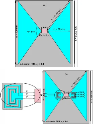
[image:3.595.211.537.253.686.2]The topologies of the proposed antenna with and without CSRRs are shown in Figure 1(a) & Figure 1(b).
Bow-tie UWB antenna has been employed for many years in the VHF and UHF frequency ranges. However, the description of its behavior and its sizing are very fewly detailed in the literature. It consists of two triangles (characterized by the height H and the flare angle α) symmetrical with respect to the feeding point. The antenna is designed on FR4 substrate for ε =r 4.4 and loss tangent of 0.02 with thickness of 0.750 mm (Figure 1(a) & Figure 1(b)). It is fed by a 50 Ω coaxial cable.
2.1. Flare Angle α and Triangle Height H
Small advances in the description of bow-tie UWB antenna were made by Bala-nis C.A. and Chen Z.N. who proposed respectively in [16] and [17] formulae that can be used to calculate the dimensions of the structures very close to the bow-tie antenna. Unfortunately, these formulae do not give concordant results in all cases.
Taking into account the above-mentioned remarks, and referring to the expe-rimental work of Brown G.H. [18] on the triangular structure antennas, we used the formula (1) assuming that the flare angle is between 110˚ and 140˚ and that the first resonance is around 3 GHz.
110
30.5 mm 360
H= λ = (1)
2.2. CSRRs Dimension and Geometry
Since the triangles are symmetrical and equipotential with respect to the feeding point, the CSRRs must be also symmetric with respect to the feeding point to have the same potential on the entire radiation element. That allows a good band rejection.
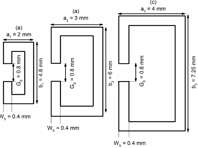
The various dimensions of the CSRRs cells determined according to the fol-lowing formula (2) are shown in Figure 2.
CSRR 2 2 g notch eff c L f λ ε
= = (2)
In “Equation (2)”, λg is the guided wavelength, c is speed of light in free
space, εeff is the effective dielectric constant and fnotch represents the central
frequency of the notched band.
(
)
1
,1
CSRR 1 1
,1 2 2 2 g S notch eff c
L a b G
f
λ ε
= = + − = (3)
(
)
2
,2
CSRR 2 2
,2 2 2 2 g S notch eff c
L a b G
f
λ ε
= = + − = (4)
(
)
3
,3
CSRR 3 3
,3 2 2 2 g S notch eff c
L a b G
f
λ ε
Figure 2. Geometry of CSRRs, (a): configuration for CSRR1 to notch 8.1 GHz band; (b): configuration for CSRR2 to notch 5.6 GHz band; (c): configuration for CSRR3 to notch 4.32 GHz band.
3. Result and Discussion
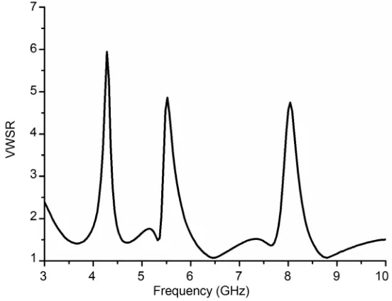
The bow-tie antenna (Figure 1) is designed with the optimized parameters val-ues listed in Table 1 such that it covers the entire FCC band from 3.1 GHz to 10.6 GHz. The simulation result of the proposed antenna is shown in Figure 3.
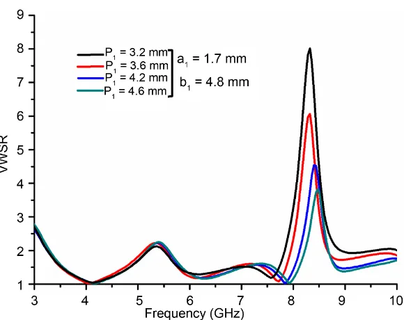
At first, study was made only with a CSRR1 in bow-tie antenna. Insertion on both sides of the dipole is made not only to ensure symmetry (equipotentiality) between the triangles but also to improve the level of the frequency band rejec-tion [16]. In his description of bow-tie antenna, it is shown that the currents are concentrated mainly on the edges. This implies that if the CSRRs cells are close to the feed point, there will be a better coupling thus allowing for good rejection of the solicited band. It should be noted that as the CSRR1 is close to the feed point, the band rejection level is excellent (VWSR = 8 at 8.3 GHz). Fur-thermore, if the size (width) of the CSRR is increased, the band shifts towards lower frequency (8.1 GHz if a1 = 2 mm). By a series of parametric study, the op-timized value of the width and the position (P1 = 3.2 mm) of the CSRR1 are de-termined. A good band rejection is obtained at 8.1 GHz. Figure 4 & Figure 5 shows the effect of the CSRR1 position and width on the simulated VSWR of the prototype.
Figure 3. Simulated VWSR of antenna without CSRRs.
Figure 4.Simulated VWSR of the UWB bow-tie antenna with CSRR1: effect of CSRR position.
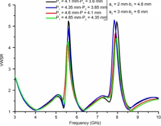
thus a cells nest allows us less clutter. A parametric study was made to investi-gate this effect on the influence of the positions of CSRR1 and CSRR2 (P1 and P2 respectively). It is observed (Figure 6) that the optimal positions of the CSRRs elements are P1 = 4.1mm and P2 = 3.6mm with virtually VWSR = 5.20 in both rejected bands centered at 8.1 GHz and 5.6 GHz.
[image:6.595.230.520.327.557.2]Figure 5. Simulated VWSR of the UWB bow-tie antenna with CSRR1: effect of CSRR size (width).
Figure 6. Simulated VWSR of the UWB bow-tie antenna with CSRR1 and 2: effect of CSRRs positions.
[image:7.595.212.539.374.630.2]Table 1. Parameters of bow-tie antenna with and without CSRRs.
Antenna parameters H W L h t
Values (mm) 30 100 58.30 0.750 0.035 CSRR1 parameters a1 b1 GS WS LCSRR1
Values (mm) 2 4.8 0.8 0.4 12.8
CSRR2 parameters a2 b2 GS WS LCSRR2
Values (mm) 3 6 0.8 0.4 17.2
CSRR3 parameters a3 b3 GS WS LCSRR3
Values (mm) 4 7.25 0.8 0.4 21.7
[image:8.595.242.503.238.430.2]Where W is the width of the triangles, L is length and h is the thickness, α =118 .
Figure 7. Simulated Return Loss of bow-tie antenna with two band notched characteristics: CSRRs optimized positions P1 = 4.1 mm-P2 = 3.6
mm.
[image:8.595.244.505.489.674.2]4.1 mm and leaving thus the third cell to P3 = 3.6 mm position (shown in Figure 1(b)). Again, after a series of simulation and parametric studies, it is observed that this is the only position of the CSRRs where the bands rejection level is good.
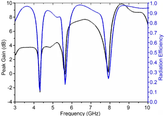
Figure 9 and Figure 10 show VSWR and S11 parameter of the proposed
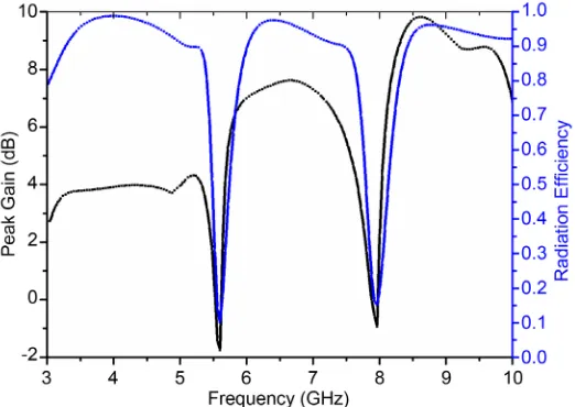
an-tenna after optimization of CSRRs positions. The simulated gain and efficiency shown in Figure 11 also validate the triple band-notch behavior of the
Figure 9. Simulated VWSR of bow-tie antenna with triple band notched characteristics: CSRRs optimized positions P1 = 4.6 mm-P2 = 4.1 mm-P3 =
3.6 mm.
Figure 10. Simulated Return Loss of bow-tie antenna with triple band notched characteristics: CSRRs optimized positions P1 = 4.6 mm-P2 = 4.1
Figure 11. Simulated Peak Gain and radiation efficiency of bow-tie anten-na with triple band notched characteristics.
proposed antenna. It is observed that for band-pass, the proposed antenna exhi-bits a nearly stable gain response.
4. Conclusion
In this letter, a compact triple band-notched UWB bow-tie antenna embedding Complementary Split Rings Resonators (CSRRs) in the antenna is presented. The proposed antenna has bandwidth covering the entire FCC range (3.1 - 10.6 GHz), along with the band notched characteristics in the IUT service band (8.025 - 8.4 GHz), in the WLAN system (5.15 - 5.85 GHz), and another band frequencies (4.10 - 4.47 GHz). The design and parametrical studies are described and validated via ANSYS EM simulations. VSWR, Return loss, Peak Gain, and Radiation efficiency triple-notch behavior of the proposed antenna. Stable an-tenna performance ensures that the proposed anan-tenna can be utilized for various UWB applications with high immunity from electromagnetic interference.
Acknowledgements
The authors would like to thank the LEAT (Laboratoired’ Electronique Anten-neet Télécommunications) of the Nice Sophia Antipolis University available to them during their internship in the Ansys-EM simulation software. One of us, Assane Ngom, would like to thank the Agence Universitaire de la Francophonie for it financial support in the framework of their mobility program.
References
Antennas with Dual Band-Notched Characteristics. IEEE Transactions on Microwave
Theory and Techniques, 54, 2800-2806. https://doi.org/10.1109/TMTT.2006.874895
[3] Hong, C.-Y., Ling, C.-W., Tarn, I.-Y. and Chung, S.-J. (2007) Design of a Planar Ul-tra Wideband Antenna with a New Band-Notch Structure. IEEE Transactions on
Antennas and Propagation, 55, 3391-3397. https://doi.org/10.1109/TAP.2007.910486
[4] Vuong, T.-P., Ghiotto, A., Duroc, Y. and Tedjini, S. (2007) Design and Characteris-tics of a Small U-Slotted Planar Antenna for IR-UWB. Microwave and Optical
Technology Letters, 49, 1727-1731. https://doi.org/10.1002/mop.22515
[5] Chu, Q.X. and Yang, Y.Y. (2008) A Compact Ultra Wideband Antenna with 3.4/5.5 GHz Dual Band-Notched Characteristics. IEEE Transactions on Antennas and
Propagation, 56, 3637-3644. https://doi.org/10.1109/TAP.2008.2007368
[6] Abdollahvand, M., Dadashzadeh, G. and Mostafa, D. (2010) Compact Dual Band- Notched Printed Monopole Antenna for UWB Application. IEEE Antennas and
Wireless Propagation Letters, 9, 1148-1151.
https://doi.org/10.1109/LAWP.2010.2091250
[7] Luo, L., Cui, Z., Xiong, J.-P., Zhang, X.-M. and Jiao, Y.-C. (2008) Compact Printed Ultra-Wideband Monopole Antenna with Dual Band-Notch Characteristic. Ele-
ctronics Letters, 44, 1106-1107. https://doi.org/10.1049/el:20081548
[8] Lin, C.C., Jin, P. and Ziolkowski, R.W. (2012) Single, Dual and Tri-Band-Notched Ultrawideband (UWB) Antenna Using Capacitively Loaded Loop (CLL) Resona-tors. IEEE Transactions on Antennas and Propagation, 60, 102-109.
https://doi.org/10.1109/TAP.2011.2167947
[9] Sarkar, D., Srivastava, K.V. and Saurav, K. (2014) A Compact Microstrip-Fed Triple Band-Notched UWB Monopole Antenna. IEEE Antennas and Wireless Propagation
Letters, 13, 396-399. https://doi.org/10.1109/LAWP.2014.2306812
[10] Mohammadian, N., Azarmanesh, M.-N. and Soltani, S. (2010) Compact Ultra-Wi- deband Slot Antenna Fed by Coplanar Waveguide and Microstrip Line with Triple- Band-Notched Frequency Function. IET Microwaves, Antennas & Propagation, 4, 1811-1817. https://doi.org/10.1049/iet-map.2009.0367
[11] Li, L., Zhou, Z.L. and Hong, J.S. (2011) Compact UWB Antenna with Four Band- Notches for UWB Applications. Electronics Letters, 47, 1211-1212.
https://doi.org/10.1049/el.2011.2334
[12] Sharma, M.M., Deegwal, J.K., Kumar, A. and Govil, M.C. (2014) Compact Planar Monopole UWB Antenna with Quadruple Band-Notched Characteristics. Progress
in Electromagnetics Research C, 47, 29-36. https://doi.org/10.2528/PIERC13121909
[13] Zhang, Y., Hong, W., Yu, C., Kuai, Z.-Q., Don, Y.-D. and Zhou, J.-Y. (2008) Planar Ultra-Wideband Antennas with Multiple Notched Bands Based on Etched Slots on the Patch and/or Split Ring Resonators on the Feed Line. IEEE Transactions on
Antennas and Propagation, 56, 3063-3068. https://doi.org/10.1109/TAP.2008.928815
[14] Kandasamy, K., Majumder, B., Mukherjee, J. and Ray, K.P. (2015) Design of SRR Loaded Reconfigurable Antenna for UWB and Narrow Band Applications. IEEE
International Symposium on Antennas and Propagation & USNC/URSI National
Radio Science Meeting, Vancouver, 19-24 July 2015, 103-104.
https://doi.org/10.1109/aps.2015.7304984
3766-3776. https://doi.org/10.1109/TAP.2016.2585183
[16] Balanis, C.A. (1997) Antenna Theory Analysis and Design. 2nd Edition, John Wiley & Sons Inc., Hoboken.
[17] Chen, Z.N. and Chia, Y.W.M. (2000) Impedance Characteristics of Trapezoidal Pla- nar Monopole Antennas. Microwave and Optical Technology Letters, 27, 120-122. https://doi.org/10.1002/1098-2760(20001020)27:2<120::AID-MOP11>3.0.CO;2-D [18] Brown, G.H. and Woodward, O.M. (1952) Experimentally Determined Radiation
Characteristics of Conical and Triangular Antennas. RCA Review, 13, 425-452.
Submit or recommend next manuscript to SCIRP and we will provide best service for you:
Accepting pre-submission inquiries through Email, Facebook, LinkedIn, Twitter, etc. A wide selection of journals (inclusive of 9 subjects, more than 200 journals)
Providing 24-hour high-quality service User-friendly online submission system Fair and swift peer-review system
Efficient typesetting and proofreading procedure
Display of the result of downloads and visits, as well as the number of cited articles Maximum dissemination of your research work
Submit your manuscript at: http://papersubmission.scirp.org/