3509
ENERGY EFFICIENCY OF MULTI-LTE MACRO CELL
CELLULAR NETWORKS: MODELLING AND ANALYSIS
MOHAMMED H. ALSHARIF
Department of Electrical and Electronics Engineering, Faculty of Engineering and Architecture, Istanbul Gelisim University, İstanbul, Avcılar 34310, Turkey
E-mail: [email protected]
ABSTRACT
This paper evaluates the impact of multi-macro cell systems on the energy efficiency of Long Term Evolution (LTE) cellular networks. Both the proposed model and the analysis of the EE in this study take into account (i) the path losses, fading, and shadowing that affect the received signal at the UE within the same cell, and (ii) the interference effects of adjacent cells. The simulation results show that the interference from adjacent cells can degrade the EE of a multi-cell cellular network. With the high interference from cell2 and cell3 (at the edge of the cell1), the number of bits that will be transferred per joule of energy is 0.78 kb/J with a 1.4 MHz bandwidth and two transmit antennas. With a 20 MHz bandwidth and two transmit antennas, the transfer rate increases to 11.17 kb/J. However, the EE will improve if the number of antennas is increased. The results of this study provide insight into the impact of the number of antennas and the interference from adjacent cells on achieving real gains in the EE of multi-cell LTE multi-cellular networks.
Keywords: Small cell; Macro-Cell LTE; Data rate; Energy efficiency; Green radio; ICT 1. INTRODUCTION
The last five years have witnessed a tremendous development in cellular networks and explosive growth in the number of mobile subscribers, due to the many data oriented services offered by cellular networks including, but not limited to, multimedia, online gaming, and high-quality video streaming. According to [1], the number of mobile subscribers is predicted to grow to 7.6 billion by 2020, and the data traffic is predicted to increase to 82 GB per subscriber per year. This unprecedented increase in the demand for data will be primarily due to high bandwidth video streaming, which will represent more than half of global mobile data traffic [2]. This unprecedented level of growth demands a significant increase in wireless network capacity, which will lead to an increase in both energy consumption and operational expenditures (OPEX). These increases will be due to the significant increase in the number of base stations (BSs), which are considered the primary source of energy consumption in cellular networks [3], that will be used to meet the needs of mobile subscribers. In addition, EE in cellular networks is a growing concern for cellular network operators, not only to maintain profitability but also to reduce the overall environment effects. A
consensus is being reached that the cellular network sector is one of the major contributors of greenhouse gas (GHG) emissions. According to [4], the amount of carbon dioxide (CO2) that is emitted by the mobile sector is expected to rise to 179 MtCO2 by 2020, which represents 51% of the information and communication technology (ICT) sector’s carbon footprint.
ISSN: 1992-8645 www.jatit.org E-ISSN: 1817-3195
[image:2.612.89.541.57.324.2]3510
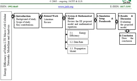
Figure 1: Schematic map of the structure of this paper
The rest of the paper is organized as follows (The outline of this paper is provided in Fig. 1). Sect. 2 summarizes related work previously conducted in this field. The system and mathematical model are described in Sect. 3. The simulation setup is presented in Sect. 4. Sect. 5 presents the results and discussion, and Sect. 6 discusses the conclusions from this investigation.
2. RELATED WORKS
Many interesting studies have been conducted to address the issue of ‘greener’ cellular networks that are less expensive to operate. In [6-8], different approaches for EE in the Universal Mobile Telecommunications System (UMTS) cellular networks during low-traffic periods were presented. Reference [6] investigates the possibility of switching off some cells and BSs in the UMTS network during low-traffic periods, while still guaranteeing the quality of service constraints in terms of blocking probability and electromagnetic exposure limits. The authors analyzed three types of scenarios: residential, office and hierarchical. Their simulation results demonstrated that the EE had significantly improved. The same authors presented an improvement of their previous work in which they proposed a dynamic network planning scheme for switching BSs off and on and considered both a uniform and a hierarchical scenario [7]. The results they obtained were extended in [8], where they proposed a set of realistic regular cell topologies where each configuration achieves a specific energy saving ratio by turning off three out of four or eight out of
nine BSs. In addition, two approaches that achieve EE were proposed in [9]: (i) a greedy centralized algorithm, and (ii) a decentralized algorithm. The simulation results demonstrated the EE of the proposed algorithms and the trade-off between energy savings and coverage guarantee. Reference [10] proposed a dynamic EE algorithm based on blocking probabilities. The BSs are switched off based on traffic variation with respect to a blocking probability constraint. Reference [11] studied the optimal number of active BSs that will be used based on the trade-off between fixed power and dynamic power. Lorincz et al. (2012) presented a novel optimization model that can be used for energy-saving purposes at the level of a UMTS cellular access network [12]. Bousia et al. (2012) proposed a switch-off decision-making scheme based on the average distance between BSs and UEs, where the BS that is at the maximum average distance will be switched off [13].
3. SYSTEM AND MATHEMATICAL MODEL
This section begins with an introduction of the system model that was considered in this study and then addresses the details of the mathematical. The eNB coverage range is configured as a typical hexagonal cell, and the LTE cluster is included on three hexagonal cells. In this case, the main interference is assumed to be transmitted from two adjacent cells. Therefore, the UE can receive the expected signal from eNB1 and interference signals
from eNB2 and eNB3 in the adjacent cells, as shown
3511
Figure 2: Cellular network system model
3.1 Energy Efficiency
Based on the LTE cellular network system model shown in Fig. 1, the EE mathematical model can be written as [14],
(1)
In the EE mathematical model given in Eq. (1), the path loss, fading, shadowing, and the interference effects from adjacent cells are considered. However, for ease of understanding, this EE model is simplified and explained in the following paragraphs.
The EE, measured in bits per joule, is defined as the total amount data delivered (in bits per second) divided by the total power consumed by the eNB (in watts) and can be expressed mathematically as [14],
eNB tot
P R
EE (2)
where R is the total data delivered to the UE, and eNB
tot
P
is the total power consumed.P
toteNB can be calculated by the following formula [15],
Cool MS
DC
BB RF PA
eNB tx
TRX eNB
tot
P
P
P
N
P
1
1
1
1 _
(3 )
where
DC,
MS,
and
Cool denote losses incurred by the DC-DC power supply, main supply, and cooling, respectively.P
tx,
P
RF,
andBB
P
are the output power per transmit antenna, radio frequency, and baseband power,respectively.
PA denotes the power amplifier (PA) power efficiency, and NTRX is the number oftransceivers, which can be computed as follows [15],
NTRX= NCarr × NSect × NAnt (4)
where NCarr,NSect,and NAnt denote the number of carriers, sectors, and antennas, respectively.
3.2 Data Rate
Based on the Shannon theory, the maximum achievable data rate for the communication system is given by [14],
ISSN: 1992-8645 www.jatit.org E-ISSN: 1817-3195
3512 where BW is the bandwidth, and SINR is the signal to interference plus noise ratio, which can be calculated by the following formula,
o I rx N P P SINR
(6)
where PI is the interference power of the
neighbour eNB2 and eNB3 (which are denoted as
PI2 and PI3, based on Fig. 2);No is the noise in
wireless channels; and Prx is the received power.
Three phenomena primarily affect the properties of the received power: (i) propagation path loss, (ii) multi-path (small-scale) fading, and (iii) shadow (large-scale) fading.
3.3 Propagation Model
The basic propagation model for the received power (Prx) can be written as follows
[16],
Prx = Ptx-eNB1 + G1 – PL_MBS – σ1 (7)
where Ptx-eNB1 and G1 denote the transmitted
power and the total antenna gain at eNB1,
respectively; PL_MBS represents the path loss
model; and σ1 is the shadow fading margin.
The transmission power of eNB1,
denoted as Ptx_eNB1 , depends on the radius of
coverage and the signal propagation fading. To simplify the model derivation, the macro BS transmission power is normalized as Po = 40 W
with the coverage radius Ro = 1 km. Similarly,
Ptx_eNB1 with coverage radius Rc1 is denoted by
[17, 18],
Ptx_eNB1 = Po×
R
c1/
R
o
(8)The 3GPP Urban Macro (UMa) non-line of sight (NLOS) propagation model for the channels between eNBs and UEs is considered in this study [19]. The 3GPP UMa-NLOS path loss model is expressed as a function that includes the frequency (fc) in GHz, macro-BS antenna height
(heNB1) in meter, UE antenna height (hUE) in
meter, average building height (hbl) in meter,
street width (w) in meter, and radius of the macro-cell (Rc1) in meter, as follows in the next formula,
(3.2
log(11.75 )
4.97) log 20 3 log log 1 . 3 42 . 43 log 7 . 3 37 . 24 log 5 . 7 log 1 . 7 04 . 161 2 10 10 1 10 1 10 1 10 2 1 10 10 UE c c eNB eNB eNB bl bl MBS L h f R h h h h h w P (9)The interference power of the adjacent cells that affect the received signal at the UE can be expressed mathematically as,
PI =
3
2 tx-eNBi i L_MBSi i
)
-P
-G
+
(P
i
(10)The transmission power of eNB2 and
eNB3 and the 3GPP UMa-NLOS path loss model
are expressed similarly to eNB1, as given in the
following equations,
Ptx_eNBi =
3
2 i
Po×
o ci
R
R
/
(11)
(3.2
log (11.75 )
4.97)log 20 3 log log 1 . 3 42 . 43 log 7 . 3 37 . 24 log 5 . 7 log 1 . 7 04 . 161 2 10 10 10 10 10 2 10 10 UE c cx eNBi eNBi eNBi bl bl MBSi L h f R h h h h h w P (12)
where ∆ represents the distance between the UE and the edge of the cell1 within cell1. For example,
if the UE is being determined at the edge of cell1,
∆ will equal zero.
4. SIMULATION SETUP
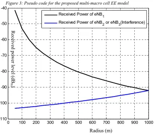
The simulation layout is given in Fig. 2, and more details of the simulation parameters are shown in Table 1. Note that the simulation parameters for both cell2 and cell3 are similar to cell1. The pseudo code for the proposed multi-LTE macro cell EE model is presented in Fig. 3.
5. RESULTS AND DISCUSSION
3513 effects of the path loss, fading and shadowing on the received power level at the UE within cell1, as
well as the interference effects from adjacent cells (cell2 and cell3) on the received power level at the
UE over different cell radii. Because the EE is a function of both the data rate and the total eNB power consumption, the second part of the discussion focuses on the data rate that will be delivered to the UEs under the effects of propagation path loss, multi-path (small-scale) fading, shadow (large-scale) fading and the interference power of the adjacent cells. The final part of this section evaluates the EE based on the proposed multi-LTE macro eNBs system model.
The received signal power decreases rapidly as the transmit-receive distance (radius of cell) increases (Prx (r)=Ptx ꞏ r-α). This power
decrease is because the path loss, fading and shadowing within the cell, as well as the interference of adjacent cells and noise, are increasing. Fig. 4 shows the effect of both the
path loss, fading and shadowing within cell1 and
of the interference of adjacent cells (cell2 and
cell3) on the received power level at the UE
versus cell radii.
It is clear that when the radius increases, the received power level of eNB1 decreases and
the interference power of eNB2 and eNB3
increases, reaching a maximum at the edge of cell1. This can be expressed as the SINR given in
Eq. (6) and defined as the ratio between the received power level of eNB1 and the interference
power of eNB2 and eNB3 plus noise. According to
the basic Shannon formula, Eq. (5), the data rate is directly proportional to the number of antennas and the channel bandwidth multiplied by the logarithm of the SINR.
[image:5.612.105.509.359.736.2]
Table 1: List of simulation parameters [15, 20]
Item Parameter Acronym MBS Unit
Network parameters
frequency fc 2.6 GHz
Bandwidth BW 1.4 -20 MHz
Max. Cell radius Rc1 1 km
BS parameters
BS transmission power Ptx_eNB1 40 46 W dBm
(PA) power efficiency ηPA 38.8 %
Radio frequency PRF 10.9 W
Baseband PBB 14.8 W
DC-DC power loss σDC 6 %
Main supply loss σMS 7 %
Cooling loss σCool 9 %
Total power consumption eNB tot
P 965 W
BS antenna height h eNB1
25 m
Tx antenna gain G1 7 dB
Number of antennas NAnt 2 #
Number of sectors Nsec 3 #
UE parameters
Thermal noise density No 174 dBm/Hz
Noise figure Nf 9 dB
Implementation margin IM 3 dB
UE antenna height hUE 1.5 m
Propagation losses
Morphology Urban
Propagation model PL_MSB 3GPP UMa-NLoS dB
Avg. building height hbl 20 m
Street width Wst 20 m
SINR SINR -5.1 to 18.6 dB
Shadow fading margin σ 6 dB
ISSN: 1992-8645 www.jatit.org E-ISSN: 1817-3195
[image:6.612.93.520.90.570.2]3514
Figure 3: Pseudo code for the proposed multi-macro cell EE model
0 100 200 300 400 500 600 700 800 900 1000 -110
-100 -90 -80 -70 -60 -50 -40
Received Power of eNB1
Received Power of eNB2 or eNB3(Interference)
Figure 4: Cell radii versus received power level at Ptx_eNB1= Ptx_eNB2 =Ptx_eNB3 = 46 dBm
Radius (m)
Received powe
r level (dB
[image:6.612.173.484.421.688.2]3515
-2.86 -2.94
-3.02 -3.11
-3.19 -3.28
-3.37 -3.46
-3.56 -3.67
1.43 510
1520 0
1 2 3
[image:7.612.101.541.67.314.2]x 107
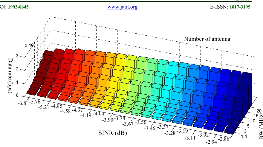
Figure: 5 Data rate versus different SINR values for different BWs at Ptx_eNB1=46 dBm and NAnt= 2
Fig. 5 shows the relationship between the data rate and the SINR values for different bandwidths and for two transmit antennas. It is clear that when the SINR decreases, the data rate is low because the demodulation error rate becomes large as a result of the increase in both noise and interference. This often occurs at the edge of the cell. Low-order modulation, such as Quadrature Phase Shift Keying (QPSK), is more robust and can tolerate higher levels of interference but provides a lower transmission bit rate. High-order 64-Quadrature Amplitude Modulation (64QAM) offers a higher bit rate but is more susceptible to errors due to its higher sensitivity to interference, noise and channel
estimation errors. Therefore, 64QAM is useful only when the SINR is sufficiently high. Additionally, a high bandwidth can be more efficient than a low bandwidth within the same size coverage area due to the increased number of bits that will be transferred, resulting in a higher data rate. At the edge of cell1 (radius equal 1 km)
where the SINR is the lowest (-6.8 dB), the total data rate with a 1.4 MHz BW and two antennas can be up to 0.75 Mbps. With a 20 MHz BW the total data rate can be up to 12.24 Mbps with the same number of antennas. However, the multiple signal paths due to multiple antennas at the transmitter are responsible for the large throughput.
BW (MHz)
SINR (dB)
Data rate (bps
)
-2.86 -2.94 -3.02 -3.11 -3.28 -3.46
-3.67 -3.90 -4.19
-4.58 -5.21
-6.8
-3.19 -3.37 -3.56
-3.78 -4.04
-4.37 -4.85
-5.76
ISSN: 1992-8645 www.jatit.org E-ISSN: 1817-3195
3516
1.4 3
5
10
15
20 2
4 8 0
2 4 6
x 107
[image:8.612.131.503.62.328.2]BW (MHz) ber of Antenna
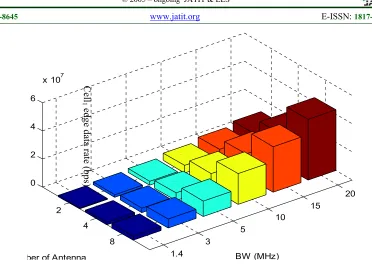
Figure 6: Data rate versus different BWs values for different number of antennas at Ptx_eNB1=46 dBm and the
lowest SINR (at edge of cell1)
Fig. 6 summarizes the data rate that can be achieved with various numbers of antennas for different BWs at the edge of cell1. It is clear that
when using eight antennas, the data rate (3.02 Mbps with 1.4 MHz BW, and 43.11 Mbps with 20 MHz BW, respectively) is 4 times greater compared with using two antennas (0.75 Mbps with 1.4 MHz BW, and 10.78 Mbps with 20 MHz BW, respectively).
The large BW and the large number of antennas combined with a high SINR provide a high order modulation and coding scheme, which increases the number of bits transferred per joule of energy and thus improves the EE of the cellular network. EE performance versus the SINR for different BWs is shown in Fig. 6, based on the multi-LTE macro eNBs network system proposed in Fig. 2. The total power consumption
P
toteNB in this type of system grows proportionally with transmission power of the base station Ptx_eNB as isshown in Eq. (8).
As shown in Fig. 7, the EE achieved at a 1.4 MHz BW and two antennas at the edge of the cell1, where the SINR is -6.8 dB, can be up to
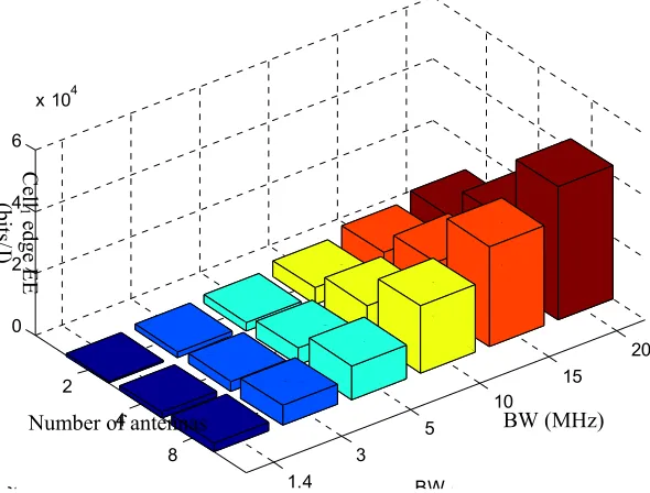
0.781 kbits /J. This result was computed using Eq. (2), a data rate of 0.75 Mbps taken from Fig. 5, and by dividing by the total power consumption of 965 W given in Table 1. However, with a 20 MHz BW and two antennas, the EE can be as high as 11.17 kbits/J, resulting in data rates of up to 12.24 Mbps, as shown in Fig. 5. The data rate increases with an increasing number of antennas, and the EE is a function of the data rate (as shown by Eq. (2)). Therefore, the EE improves with a larger BW size and a larger number of antennas. Fig. 7 shows EE versus the number of antennas for different BWs at the edge of cell1.
It is clear from Fig. 7 that with eight antennas the EE is 3.13 kbits/J at a 1.4 MHz BW and is 44.68 kbits/J at a 20 MHz BW.
Cell
1 edge
data
rate (
3517
Figure 7: Energy efficiency versus different SINR values for different BWs at Ptx_eNB1= Ptx_eNB2 =Ptx_eNB3 = 46
dBm and NAnt=2
1.4 3
5
10 15
20 2
4 8 0
2 4 6
x 104
BW (MHz) ber of Antenna
Figure 8: Energy efficiency versus different BW values for different number of antennas at Ptx_eNB1= Ptx_eNB2
=Ptx_eNB3 = 46 dBm and at the lowest SINR (at edge of cell1)
6. CONCLUSION
This paper presented a model and an investigation of the EE of multi-LTE macro cell system cellular networks. The results show a data rate of up to 24 Mbps and an EE of up to 24.91
kb/J under the best SINR conditions and a 20 MHz BW with two transmit antennas. The results also show a data rate of up to 0.75 Mbps and an EE of 0.78 kb/J when facing the worst SNIR environments (at the edge of cell1) with a 1.4
MHz BW and two transmit antennas. Throughput at the transmitter increases with an increasing
BW (MHz) Number of antennas
Cell
1 edge E
E
(b
[image:9.612.174.469.378.602.2]ISSN: 1992-8645 www.jatit.org E-ISSN: 1817-3195
3518 number of antennas due to the multiple signal paths provided by multiple antennas. Therefore, when eight antennas are used, a data rate of up to 3.02 Mbps and an EE of up to 3.13 kb/J are possible under the worst SNIR environments and with a 1.4 MHz BW. Data rates of up to 44.11 Mbps and an EE of 44.68 kb/J are possible with a 20 MHz BW. These results provide insight for mobile operators to consider the number of antennas and interference from adjacent cells to achieve gains in the EE of multi-cells LTE cellular networks.
REFERENCES
[1] J. Wu, Y. Zhang, M. Zukerman, and E. Yung, "Energy-Efficient Base Stations Sleep Mode Techniques in Green Cellular Networks: A Survey,'' IEEE Communications Surveys & Tutorials, vol. 17, no. 2, pp. 803 - 826, 2015.
[2] Cisco Systems, Inc. 2016. Cisco Visual Networking Index: Global Mobile Data Traffic Forecast Update, 2015 – 2020.
[Online] Available:
http://www.cisco.com/c/en/us/solutions/collat eral/service-provider/visual-networking- index-vni/mobile-white-paper-c11-520862.html, accessed 07 Oct., 2019. [3] M. H. Alsharif, R. Nordin, and M. Ismail,
"Survey of Green Radio Communications Networks: Techniques and Recent Advances," Journal of Computer Networks and Communications, vol. 2013, 2013. [4] Suarez, L., Nuaymi, L., & Bonnin, J.-M. "An
overview and classification of research approaches in green wireless networks," EURASIP Journal on Wireless Communications and Networking, vol. 2012, no. 1, pp. 1-18, 2012.
[5] M. H. Alsharif, R. Nordin, and M. Ismail, "Classification, recent advances and research challenges in energy efficient cellular networks," Wireless personal communications, vol. 77, no. 2, pp.
1249-1269, 2014.
[6] Chiaraviglio, L., Ciullo, D., Meo, M., & Marsan, M. "Energy-aware UMTS access networks," In Proceedings of 11th International Symposium on Wireless Personal Multimedia Communications (WPMC’08), pp. 1–5, 2008.
[7] Chiaraviglio, L., Ciullo, D., Meo, M., & Marsan, M. "Energy efficient management of UMTS access networks," In Proceedings of
21st International Teletraffic Congress (ITC 2009), pp. 1–8, 2009.
[8] Marsan, M., Chiaraviglio, L., Ciullo, D., & Meo, M. "Optimal energy savings in cellular access networks. In Proceedings of IEEE International Conference on Communications Workshops (ICC Workshops), pp. 1–5, 2009.
[9] Zhou, S., Gong, J., Yang, Z., Niu, Z., & Yang, P. "Green mobile access network with dynamic base station energy saving," In Proceedings of MobiCom’09, pp. 1–3, 2009. [10] Gong, J., Zhou, S., Niu, Z., & Yang, P.
"Traffic-aware base station sleeping in dense cellular networks," In Proceedings of 18th International Workshop on Quality of Service (IWQoS), pp. 1–2, 2010.
[11] Xiang, L., Pantisano, F., Verdone, R., Ge, X., & Chen, M. "Adaptive traffic loadbalancing for green cellular networks," In Proceedings of 22nd IEEE International Conference on Personal Indoor and Mobile Radio Communications (PIMRC), pp. 41 45, 2011. [12] Lorincz, J., Capone, A., & Begusic, D.
"Impact of service rates and base station switching granularity on energy consumption of cellular networks," EURASIP Journal on Wireless Communications and Networking, vol. 2012, no. 1, pp. 1–24., 2012.
[13] Bousia, A., Antonopoulos, A., Alonso, L., & Verikoukis, C. "Green distance-aware base station sleeping algorithm in LTE-advanced,"
In Proceedings of IEEE International
Conference on Communications (ICC), pp. 1347–1351, 2012.
[14] Chen, T., Yang, Y., Zhang, H., Kim, H., and Horneman, K., "Network energy saving technologies for green wireless access networks," IEEE Wireless Communications, vol. 18, no. 5, pp. 30-38, 2011.
[15] Auer G., Blume O., Giannini V., Godor I., Imran A M., Jading Y., Katranaras E., et al. (2010). Energy efficiency analysis of the reference systems, areas of improvements and target breakdown. EARTH project report, Deliverable D2.3, 1-68.
[16] Debus, W,"RF Path Loss & Transmission Distance Calculations", Axonn, LLC, New York, 2006.
3519 [18] Bojic, D., Sasaki, E., Cvijetic, N., Wang, T.,
Kuno, J., Lessmann, J., Schmid, S., Ishii, H., & Nakamura, S, "Advanced wireless and optical technologies for small-cell mobile backhaul with dynamic software-defined management", IEEE Communications Magazine, vol. 51, no. 9, pp. 86- 93, 2013. [19] 3GPP TR 36.814, V9.0.0. 2010. Technical
Specification Group Radio Access Network; Evolved Universal Terrestrial Radio Access (E-UTRA); Further advancements for EUTRA physical layer aspects, Release 9. Technical Report. [Online] Available: http://www.qtc.jp/3GPP/Specs/36814-900.pdf, accessed 07 Oct., 2019.
[20] Stefania, S., Issam, T., & Matthew, B. 2011 "LTE—the UMTS long term evolution: From
theory to practice", 2nd Edition. New York:
![Table 1: List of simulation parameters [15, 20]](https://thumb-us.123doks.com/thumbv2/123dok_us/8897716.953720/5.612.105.509.359.736/table-list-simulation-parameters.webp)