An Adaptive Technique for the Mitigation of GPS
Cross-Correlation
A. Sreenivas,
PhD.M.N.V Pavan Kumar
Assocoate Professor M.Tech(RF&MWE)
Department of E.C.E, Department of E.C.E, GITAM Institute of Technology GITAM Institute of Technology
GITAM University GITAM University
ABSTRACT
GPS is a CDMA system using DSSS, and the length of the C/A cod used by GPS L1 band civil signal is 1023chips. As the Cross-Correlation peak between the C/A codes is not zero, it will degrade the performance of the detection probability. Detection of weak signal is becoming important in many applications like GPS remote sensing etc. Cross-Correlation caused by GPS Gold codes are representing significant problem in the observation of weak GPS signals. Measurement performance for high precision applications can significantly degrade by cross correlation properties of GPS. Sub-space projection techniques represent one of the numbers of different approaches that are available for cross-correlation mitigation, although these techniques have traditionally not been used due to computational complexity. An alternative technique to the use of full space projection is a sub-optimal approach i.e., otherwise based on the same principle, by the use of non-standard de-spreading codes that are not matched to weak signal spreading code but instead are modified to be orthogonal to each other strong signal spreading codes that are present at the time of observation of GPS signals. One such technique here we have is called Adaptive Modeling of Local-Code Replica.
Keywords
Cross-Correlation, C/A code, gold codes and modeling.
1.
INTRODUCTION
A GPS receiver operating in weak signal environments (like inside buildings or urban canyons) can simultaneously receive strong LOS (line-of-sight) signals as well as attenuated weak signals from satellites as in [1]. This will bring a problem that the receiver cannot receive sufficient normal signals from satellites, some received signals are reflected by buildings or shadowed by trees, and if these signals are so weak that it might be shaded by the normal signals resulting in cross-correlation problem.
Cross correlation is Multiple access interference (MAI) in code-division multiple access (CDMA) systems such as GPS Navigation system. In the case of GPS where n is 10, it can be seen that for 75% of the code phases, there is negligible cross-correlation, but for the other 25% the dynamic range is limited to approximately 24 dB. Additional protection was desired because the legacy coarse acquisition (C/A) code could not offer more than approximately 24dB of cross-correlation protection.
With aim to enhance receiver’s sensitivity, many schemes such as successive interference cancellation and parallel interference cancellation are proposed previously.
Cancellation techniques resolve the problem by constructing the strong signal and subtracting it from the input signal data-stream before baseband down-conversion and de-spreading. The main advantage of cancellation method is that they are relatively simple. Subspace projection techniques represent an alternative approach to resolving the cross-correlation problem. With these techniques, rather than using a de-spreading code that is matched to the transmitted code of the weak signal, a different code that rejects the strong signal cross correlations while still being able to observe the desired weak signal is used instead, with the new de-spreading code having the property of being able to extract the component of the weak signal subspace that does not lie within the interference subspace. The reason for the method not being widely used is due to the difficulty in constructing the required codes in real time, with the code construction technique requiring a significant amount of matrix arithmetic on vectors and matrices that have a length defined by the number of samples in each C/A code epoch. This is a possible solution to the MAI problem, namely minor modification of the locally generated PRN code-replica cr to
some other code-replica cr*such that the new strong/weak CC sequence becomes balanced.
2.
CORRELATION PROPERTIES OF
C/A CODE
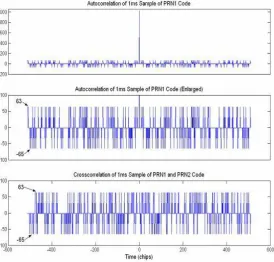
The Coarse Acquisition (C/A) is the signal mainly used for civilian applications and it is characterized by a 1023 chips long periodic sequence with chipping rate equal to 1.023 MHz. Therefore an entire period of the code lasts 1ms. One of the most important properties of the C/A codes is their correlation result. The C/ A-code autocorrelation peaks are higher than cross-correlation peaks by just 21-24 dB, which can cause false acquisition as in [4]
The Gold codes are not orthogonal but near orthogonal, implying that the cross correlations are not zero but have small values. The cross correlation of any 2 GPS L1 C/A codes takes on only three values. These values are -1, -t and t – 2.
The cross-correlation between the C/A codes of two satellites is defined as
CA
t
CA
t
dt
R
ij i(
)
j(
)
(1)Where CAi is the C/A code for the i-th satellite and CAj is the
C/A code for the j-th satellite and i=j. For the C/A code n=even=10, thus, P=1023 as in [4].
[image:2.595.21.296.204.466.2]Figure 1. Auto correlation and cross-correlation of GPS Gold Codes
Table 1. Occurrence of Cross-Correlation of C/A Code
Code Period Number of Shift Register Stages Normalized Cross-Correlation Level Occurrence
P=2n-1
n=odd -2(n+1)/2+1/P -1/P 2(n+1)/2-1/P
0.25 0.5 0.24
P=2n-1
n=even 2(n+1)/2+1/P 1/P 2(n+1)/2-1/P
0.125 0.75 0.125
3.
CONCEPT OF CROSS
CORRELATION
MITIGATION
The total signal received by the GPS receiver is by a strong signal (SS1) which modulated by PRN1 and a weak signal
(WS1), modulated by PRN2 then total composed signal can be
described by
2
1
1
1
PRN
W
PRN
S
s
s
(2)Let the received signal correlate with local code replica PRN2 code PN2R, the correlation result is
[
PN
2
R
(
S
PRN
1
W
PRN
2
)]
C
R s s (3)Here ∑ means sum of cross correlation result, since the standard correlation between PRN2 and PN2R is 1, so this can be given as:
(
S
s
PRN
1
W
s1
PRN
2
)
(4)In this method, the main problem is how to modify the local C/A code that eliminates the cross-correlations. For this, assume two binary pseudo-random sequences (PRN) cw(i) and
cs(i) both of length L, the cross-correlation between the two
sequences(CCws(i)) is calculated as,
)
(
)
(
)
(
)
(
)
(
)
(
, , 1N
CC
CC
i
CC
i
CC
i
c
i
c
i
cc
csM cw csM cw j i ws ws s w ws
(5)
where cw(i) is the weak signal PRN and cs(i) is the strong
signal PRN and ccws(i) denotes the cross correlation sequence,
CCws(j) denote the partial
cross correlation between weak signal PRN code and strong signal PRN code. The value i is from 1 to N, and j ∈ [1, N] . A w subscript refers to a weak signal PRN and an s subscript refers to strong signal.
Thus, a non-zero cross-correlation ccws occurs because the
cross correlation sequence ccwsis unbalanced, which means
the number of 1's is different to the number of -1's. It is necessary to continually adjust the local code-replica as the relative code phases vary due to satellite Doppler or user motion. This immediately suggests a method by which the cross correlations may be mitigated, i.e., modifying the weak PRN cw. The method was proposed for both cases, single
strong signal masking a weak signal and multiple strong signals masking a weak signal resulting in MAI. The following sections explore this concept in more detail considering a method called Adaptive Modeling of Local Code-Replica (AMLCR).
4.
ADAPTIVE MODELING OF LOCAL
CODE-REPLICA
4.1
Concept and Pseudo-Code Description
of Single Strong Signal Case
The idea of AMLCR is rather than using a dispreading code cw(i)that is exactly matched to the weak signal, a slightly
different dispreading code cŵ (i) that is close to cw(i)is used.
considered first. In all such cases, it is assumed that the strong signal is being tracked and as such, the sample code sequence for the strong signal cs1(i) is available and the effects of data
bits on the strong signal are initially ignored. One simple method to generate the required code is to make immediate changes to the starting code until the cross correlation has been reduced to the required level. To do this, the cross correlation for the next epoch is pre-calculated thereby determining the amount of change required to eliminate the cross correlation as in [10]. This is followed by the modification process, which for a single strong C/A code signal requires approximately 32 chips in a sequence of 1023 chips be modified since the cross correlation level is either –65 or 63. To achieve this, the cross-correlation (CC) that would occur without any mitigation ccw,s(1,1)(Nts) is
calculated prior to the start of each code epoch so that the magnitude of the changes required to eliminate the CC can be determined. This process is explained through algorithmic representation expressed as pseudo-code as followed as in [12]
1. Set the sample weighting-factor W to 2, when a sample is inverted this being an amount by which the cross-correlation changes.
2. For the next C/A code epoch ccw,s(1,1) calculate the
cross correlation (CC) and store this value in the CC register .
3. Calculate the cross-correlation sequence elements ccw,s(1,1)(i) for the current C/A code epoch being
mitigated. These values are used in step 5b and 5c. 4. Start the process of generating the modified code
cŵ1 by setting cŵ1 to cw1 at the start of the C/A code
epoch
5. For each sample n∈ [1, N]in the C/A code chip sequence cŵ1(nts)
a. If the magnitude of CC is less than the desired threshold then do nothing and break from the loop.
b. If CC > 0 and ccw,s(1,1)(nts)>0
cŵ1(nts)= - cŵ1(nts) and CC = CC – W
c. If CC < 0 and ccw,s(1,1)(nts)<0 cŵ1(nts)= -
cŵ1(nts) and CC = CC + W
4.2
Concept and Pseudo-Code Description
of Multiple Strong Signal Case
When there are multiple strong signals, the single strong signal algorithm fails. But it would be possible to use this algorithm where by taking the strong signal as a linear combination of all of the codes. These include the fact that the composite strong signal code is no longer single bit thereby making the modeling process becomes difficult as in [10]. This can be achieved by considering changes are only made to a despreading code cw1 provided that those changes do not
degrade other cross-correlations. where the changes made to cw1 have the effect of driving ccw,s(1,1)(Nts),…, ccw,s(1,p)(Nts),…,
ccw,s(1,P)(Nts) to small values. The single-strong signal concept
can also be applied in the case of multiple strong signals, except hat the locations at which changes can be made to cw1
are limited by the PRN sequences of other strong signals.
These limitations on ccw,s(1,2),…, ccw,s(1,P) being unchanged can
be achieved by making changes at pairs of indices n↑ and n↓ such that ccw,s(1,2)( n↑ts)+ ccw,s(1,2)( n↓ts),…, ccw,s(1,P)( n↑ts)+
ccw,s(1,2)( n↓ts) are zero, but ccw,s(1,1)( n↑ts)+ ccw,s(1,1)( n↓ts) is
positive or negative as required. To show how to achieve this objective this process is explained through algorithmic representation expressed as pseudo-code as followed, as in [12]
1. Set the sample weighting-factor W to 2, when a sample is inverted this being an amount by which the cross-correlation changes.
2. Calculate each strong signal cross-correlation ccw,s(1,1)(Nts) for the next C/A code epoch, storing
the values in registers CCp and where p is in the
range of 1 to P. These values determine whether adjustments are required and the amount of adjustment.
3. For the current C/A code epoch being mitigated, calculate the cross correlation sequence elements ccw,s(1,1)(nts),…, ccw,s(1,p)(nts),…, ccw,s(1,P)(nts). The
values should be added to a first-in first out (FIFO) queue (such as a shift register) and a small history of say R elements stored, where larger values of R increase the likelihood of locating instances where the required constraints are satisfied. These elements are used during step 5b and 5c.
4. Initiate the process of generating the modified code cŵ1 by setting cŵ1 to cw1. at the start of the C/A code
epoch
5. For the operation that follows, define the set of strong signals to be P, where the operations that follow require selecting an element p from P and then defining a second set NP which is P with the element p removed. This corresponds to the single signal p whose cross correlation is being reduced and the remaining set of signals np∈NP whose cross correlations need to remain unchanged during this process.
For each strong signal p∈ P,define NP=P-{p}
a. For each chip-sample n in the current strong code sequence If the magnitude of register CCp is less
than the desired threshold then break from the inner loop and continue onto next strong signal.
b. From the history of values stored in the FIFO queue, locate indices n↑ and n↓ where ccw,s(1,np)( n↑ts)+
ccw,s(1,np)( n↓ts) is 0 for all the signals np∈NP
simultaneously. For the strong signal p being mitigated, we require ccw,s(1,p)( n↑ts)+ ccw,s(1,p)( n↓ts)
be positive/negative depending on the sign of the cross-correlation. When pairs of indices are located, adjust cŵ1(n↑ts)= -cŵ1(n↑ts), cŵ1(n↓ts)= -cŵ1(n↓ts) and
adjust CCp so that its magnitude is reduced by 2W
(a ‘chip-flip’for 1-bit codes).
The GPS Receiver setup at [3] is shown below
[image:4.595.318.553.171.532.2]Figure 2. GPS Receiver setup at NARL
Figure 3. GPS Receiver front view
6.
Outputs
To confirm that the proposed technique is effective in enhancing the mitigation of MAI, Validation of AMLCR was performed in MATLAB®. The simulation consists of three steps.
i.) The first step of the simulation was generation of a C/A code epoch of specified satellites. ii.) The Second step of the simulation is to
estimate the cross correlation level.
[image:4.595.98.236.405.505.2]The third step in the simulation is to perform the proposed AMLCR technique. A simple example with two length 31 Gold codes is given in Fig 4 at a code phase offset for which significant cross correlations occur. It can be seen that the partial CC is driven to a small value when the process has been applied and that the PRN changes are applied near the start of the code sequence.
Figure 4. Left rows 1 to 4 shows strong signal PRN, Weak Signal PRN-Pre AMLCR, CC Sequence Pre AMLCR, Partial CC Pre AMLCR, Right rows 1 to 4 shows strong
signal PRN, Weak Signal PRN-Post AMLCR, CC Sequence Post AMLCR, Partial CC Post AMLCR
A simple example with three length 31 Gold codes is given in Fig 5 at a code phase offset for which significant cross correlations occur. It can be seen that the partial CC is driven to a small value when the process has been applied and that the PRN changes are applied near the start of the code sequence.
Figure 5. Left rows 1 to 5 shows strong signal PRN-1, strong signal PRN-2, Weak Signal PRN-Pre AMLCR, CC
Sequence Pre AMLCR, Partial CC Pre AMLCR, Right rows 1 to 5 shows strong signal 1, strong signal
PRN-2, Weak Signal PRN-Post AMLCR, CC Sequence Post AMLCR, Partial CC Post AMLCR
A simple example with four length 31 Gold codes is given (see figure 6)at a code phase offset for which significant cross correlations occur. It can be seen that the partial CC is driven to a small value when the process has been applied and that the PRN changes are applied near the start of the code sequence.
Figure 6. Left rows 1 to 5 shows strong signal PRN-1, strong signal PRN-2, strong signal PRN-3, , CC Sequence Pre AMLCR, Partial CC Pre AMLCR, Right rows 1 to 4, Weak Signal PRN-Pre AMLCR ,Weak Signal PRN-Post
AMLCR, CC Sequence Post AMLCR, Partial CC Post AMLCR
The Algorithm proposed here was implemented on 1023bit C/A Code Sequence of GPS Satellites with that are locked by GPS Receiver Antenna at [3] with the parameters tabulated for Single Strong Signal, two Strong Signal and Three Strong Signal Cases.
6.1
Single Strong Signal Case
[image:5.595.44.281.79.435.2]The first preliminary simulation result to be discussed is for the case of a single strong signal and a single weak signal. The signal parameters for the test case described here are given in below table which are taken from NovAtel OEM4 GPSolution Software at [3]
Table 2. Single Strong Signal Parameters
SV 9 15
Channel Sate Lock Lock
Doppler (Hz) 1403.9 3366.7
C_No 41 38
SNR (dB-Hz) 23 27
Measurement L1-C/A L1-C/A
Figure 7. Top row shows Weak cross-correlations (I Channel) without Mitigation, Bottom row shows Weak
[image:6.595.308.557.82.533.2] [image:6.595.311.550.87.322.2]cross-correlations (Q Channel) without Mitigation
Figure 8. Top row shows Weak cross-correlations (I Channel) with Mitigation, Bottom row shows Weak
cross-correlations (Q Channel) with Mitigation
[image:6.595.55.276.263.394.2]The below figures shows the mitigation of cross-correlation in GPS. It can be seen that the partial CC is driven to a small value when the process has been applied and that the PRN changes are applied near the start of the code sequence.
Figure 8. Top row shows Partial CC Pre AMLCR, Bottom row shows Partial CC Post AMLCR
6.2
Two Strong Signal Case
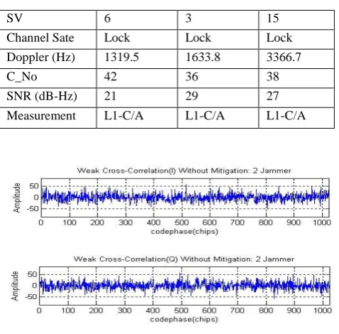
[image:6.595.55.284.500.628.2]The second preliminary simulation result to be discussed is for the case of a two strong signals and a single weak signal. The signal parameters for the test case described here are given in below table which are taken from NovAtel OEM4 GPSolution Software at [3]
Table 3. Two Strong Signal Parameters
SV 6 3 15
Channel Sate Lock Lock Lock
Doppler (Hz) 1319.5 1633.8 3366.7
C_No 42 36 38
SNR (dB-Hz) 21 29 27
Measurement L1-C/A L1-C/A L1-C/A
Figure 9. Top row shows Weak cross-correlations (I Channel) without Mitigation, Bottom row shows Weak
cross-correlations (Q Channel) without Mitigation
Figure 9. Top row shows Weak cross-correlations (I-Channel) with Mitigation, Bottom row shows Weak
cross-correlations (Q Channel) with Mitigation
The below figures shows the mitigation of cross-correlation in GPS. It can be seen that the partial CC is driven to a small value when the process has been applied and that the PRN changes are applied near the start of the code sequence.
[image:6.595.317.548.601.727.2]6.3
Three Strong Signal Case
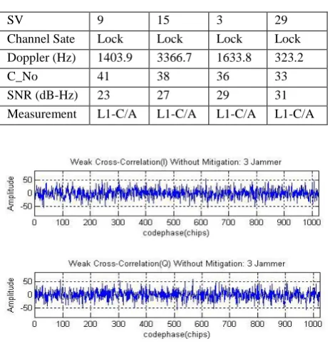
[image:7.595.316.550.74.202.2]The third preliminary simulation result to be discussed is for the case of a two strong signals and a single weak signal. The signal parameters for the test case described here are given in below table which are taken from NovAtel OEM4 GPSolution Software at [3]
Table 4. Three Strong Signal Parameters
SV 9 15 3 29
Channel Sate Lock Lock Lock Lock Doppler (Hz) 1403.9 3366.7 1633.8 323.2
C_No 41 38 36 33
SNR (dB-Hz) 23 27 29 31
Measurement L1-C/A L1-C/A L1-C/A L1-C/A
Figure 11. Top row shows Weak cross-correlations (I Channel) without Mitigation, Bottom row shows Weak
[image:7.595.52.284.169.416.2]cross-correlations (Q Channel) without Mitigation
Figure 12. Top row shows Weak cross-correlations (I Channel) with Mitigation, Bottom row shows Weak
cross-correlations (Q Channel) with Mitigation
The below figures shows the mitigation of cross-correlation in GPS. It can be seen that the partial CC is driven to a small value when the process has been applied and that the PRN changes are applied near the start of the code sequence.
Figure 13. Top row shows Partial CC Pre AMLCR, Bottom row shows Partial CC Post AMLCR
7.
Conclusion
In this project the new “Adaptive Modeling of Local Code Replica” (AMLCR) for cross-correlation mitigation based on the very simple principle technique of inverting or flipping ‘chip’ elements of the locally generated pseudo-random-noise (PRN) codes used to de-spread the received signal. Unlike traditionally formulated subspace projection methods, this technique employs simple constraints to achieve the cross-correlation reduction and also compared to Cancellation techniques which includes the cancellation of strong signals serially and simultaneously, the proposed technique is not complex and subtractions of strong signals are not necessary. Complexity in the proposed technique compared to previous technique discussed above is very much less. MATLAB simulations have been used to show the feasibility of the technique in the case of a single strong signal and up to three strong signals. The proposed technique was successfully implemented in MATLAB Platform so that he reduction in the cross-correlation magnitude was shown which results in the successful acquiring of low signal strength signals. Analysis and simulation of the technique proved the process to be feasible. Selection of the ‘chip’ elements to be inverted required locating those elements satisfying a particular set of limitations among all of the CC sequences, although as the number of strong signals was increased it was found to be progressively more difficult to achieve this. This limited the process to cases in which the number of strong signals requiring mitigation was less than or equal to four.
8. Acknowledgement
[image:7.595.54.280.467.602.2]9.
References
[1] E. P. Glennon and A. G. Dempster, "A Review of GPS Cross Correlation Mitigation Techniques," presented at The 2004International Symposium on GNSS/GPS, Sydney, Australia, 2004.
[2] Howard Grant, “Acquisition and Tracking of Weak GPS Signals as Received by Cellular Telephones”, University of Saskatchewan Saskatoon, Saskatchewan
[3] Dual Frequency GPS Receiver NARL (National Atmospheric Research Laboratory),Dept. of Space, ISRO Centre, Gadanki, Tirupate.
[4] E. D. Kaplan, Hegarty, C. J., “Understanding GPS: Principals and Applications”, 2nd Edition ed: ArtechHouse, 2006
[5] G. Sasibhushana Rao, “Global navigation Satellite Systems with essentials of satellite communications”, Tata McGraw private Limited, New Delhi.
[6] Dharma Raj Cheruku,” Satellite Communications” ,Galgotia Publications, 2005
[7] B. Hoffman – Wellenhof, H. Liehtenegger and J.Collins, ‘GPS – Theory and Practice’, Springer – Wien, New York (2001).
[8] Timothy Pratt, Charles Bostian and Jeremy Allnutt, “Satellite Communications” WSE, Wiley Publications, 2nd Edition, 2003
[9] JAMES BAO-YEN TSUI “Fundamentals of Global Positioning System Receivers A Software Approach” , 2nd ed. John wiley & sons, INC., Publications
[10] E. P. Glennon and A. G. Dempster, "A Novel GPS Cross Correlation Mitigation Technique," presented at ION-GNSS 2005, Long Beach, CA, 2005.
[11] S. Moshavi, "Multi-user detection for DS-CDMA communications," Communications Magazine, IEEE, vol. 34, pp. 124-136, 1996.
[12]
Shao-lei Yi, Journal of Measurement Science and Instrumentation ”A New Method For Mitigation Of Cross Correlation In GPS Receiver”
AUTHORS’ PROFILE
Dr. A. Sreenivas working as Associate professor in the department of E.C.E in GITAM Institute of technology, GITAM University, Visakhapatnam, A.P, India. His area of Specialization is Satellite Communications.