TORQUE ANALYSIS OF THE LOWER LIMB EXOSKELETON
ROBOT DESIGN
N. Latif A. Shaari1. Ida S. Md Isa2 and Tan Chee Jun3
1,3Faculty of Electrical Engineering, Universiti Teknikal Malaysia Melaka Durian Tunggal, Melaka, Malaysia 2Faculty of Electronic Engineering and Computer Engineering, Universiti Teknikal Malaysia Melaka, Melaka, Malaysia
E-Mail: [email protected]
ABSTRACT
Exoskeleton is a type of wearable robots that can augment the performance of an able-bodied user. There are many studies that use hydraulic actuator to actuate the lower limb exoskeleton which possesses several drawbacks like dirty, noisy and high power consumption. Therefore, electrical actuators that are clean, silent and less power consuming are used in designing the lower limb exoskeleton in this project. Hence, this project is aimed to derive the mathematical model and joint torque equations, to design a lower limb exoskeleton using electrical motors from the market and to validate the design of the lower limb exoskeleton by simulation. This project shows the progress of selecting the electrical actuators for exoskeleton in accordance to the calculations and verifying the selections via simulations. In other words, this project serves as a guide to select appropriate electrical actuators for an exoskeleton robot.
Keywords: lower limb, exoskeleton, wearable robot.
INTRODUCTION
Exoskeleton is a device that can augments the performance of an able-bodied wearer. It is used to augment the strength or the endurance of the wearer through various means. There are many types of exoskeleton which are mainly grouped into either full body exoskeleton or partial exoskeleton which further divides into upper limb exoskeleton and lower limb exoskeleton. As the name suggested, full body exoskeleton improves the performance of both the upper and lower limb of the user be it the strength or the endurance. For upper limb exoskeleton, the exoskeleton will augment the performance of user from the waist up including torso and arms. Whereas, the lower limb exoskeleton will improve the performance of the user’s legs. (Kazerooni, 2005)This research focused on the lower limb exoskeleton
The lower limb exoskeleton is further divided into two types which are series and parallel. Series lower limb exoskeletons are the ones that are applied in series with human legs to store energy and release far greater strain energy. (Herr, 2009) This type of exoskeleton works by storing energy when the user’s feet are striking the ground and release it by pushing the user to lift. By doing this, it reduces the effort for the user to move and hence reduce the metabolic cost. The most common example of this type of exoskeleton is the elastic shoes.
The other type of exoskeleton is known as parallel exoskeleton which is applied in parallel with human lower limb to change the limitations of the human body. For this type of exoskeleton there are various designs that serve different purposes for the wearer. One of which is for load transfer. This design transfer load as well as the body weight directly to the ground which will reduce the metabolic cost of the wearer for loads carrying and ultimately enhance the endurance of the wearer. One of the examples for this type of exoskeleton is Berkeley Lower Limb Exoskeleton (BLEEX) developed by University of California, Berkeley. (Zoss, Kazerooni and
Chu, 2006), (Herr, 2009) There is another design that is intended for torque and work augmentation. This sort of design augments joints torque and power of the user allowing them to lift heavy thing and perform daily activities with ease. Besides that, it also helps in reduce joint pain for user. However, this design normally does not transfer substantial load to the ground unlike the previous design mentioned. An example of this type of exoskeleton is the Hybrid Assistive Limb (HAL) developed by Cyberdyne (Bock, Linner and Ikeda, 2012), (Herr, 2009). Besides that, there is another designed that aimed to increase the users muscle endurance. This type of exoskeleton utilizes the fact that only a small portion of our muscles are fatigue during an exhaustive exercise. It redistributes the work load over a greater number of muscles, particularly the muscles that are not easily fatigue. This design simply uses spring that will stretch by unused muscles to store energy and then release it to assist the muscles that are easily fatigue. Hence, the muscle endurance of the wearer can be increased using this design. (Herr, 2009)
Since there are so many designs for exoskeleton, a design suitable for an intended application should be determined and suitable components of the exoskeleton should be selected to make sure that the exoskeleton designed works as it should.
Biomechanics of human
There are many degrees of freedom for human’s lower limb. However, it would be a waste to actuate all of them as some of them do not require high power. According to (Zoss, Kazerooni and Chu, 2006), the flexion/extension of hip, knee and ankle requires the most power which needs to be actuated. In conclusion, actuations should be provided to the flexion/extension of hip, knee and ankle whereas the other un-actuated joints are left to rotate freely to minimize the hindrance of the user’s movements.
Actuators
Actuators are the device that provide motion for the exoskeleton and hence support the wearer’s limb motion. It takes the command from the controller and provides motion according to the requirement at a certain instant. Electrical Actuator is one of the most popular choices due to its clean and silent operation as well as lower power consumption than others. (Hollerbach, Hunter and Ballantyne, 1992) Some of the electrical actuators used by previous studies include DC Servomotor, Linear Actuator and Series Elastic Actuator. DC Servomotor is a popular choice in providing actuation for robots as well as exoskeletons. (Onen, 2014) DC Servomotor can be easily controlled by controller which sends signal to it. Unlike any other actuator, the direction, speed and even position of the motor can be easily controlled by electronics. Moreover, DC servomotor provides precise positioning because of its built-in position feedback which gives an accurate control of its motion and position. . It provides clean and silent actuation of exoskeleton compared to the other which makes it suitable for application in any environment, indoor or outdoor. (Onen, 2014) This is why it is normally positioned on the exoskeleton’s joint that need to be actuated as seen in (Merodio, Cestari, Arevalo and Garcia, 2012), (Zhang, Xiang, Lin and Zhou, 2013), (Onen, 2014), (Sankai, 2003). However, there are some studies that position it away from the joint and transmit power through a drive system like chain or cable. (Banchadit, 2012),(Marcheschi,
2011) Despite the compact size, a DC Servomotor with
high torque and small size is not very easy to find. That is why Servomotors are normally coupled with suitable reducers to provide high torque and fast response motion in a small package.
There are studies that use linear actuator as their actuation system in exoskeleton design. (Stopforth, 2012), (Marcheschi, 2011) Linear actuator consists of an electric motor and a leadscrew which translate the rotational motion provided by the motor into linear motion. It is chosen by studies in (Stopforth, 2012), (Marcheschi, 2011)
because of its high load capacity which means it can provide high force output. Apart from that, reasonable price is also one of the advantages of the linear actuators. However, there are some drawbacks of this type of actuator. One of it being that it is normally large and bulky because it needs to house the components like leadscrew, motor, gearing, bearing and other components. Besides that, the moving parts of the actuator are prone to wear and tear due to frictions. The linear actuator also has a limited range of motion as the leadscrew can only extend for a limited length only.
Figure-1. Linear series elastic actuator (Walsh, 2006).
Table-2. The comparison between drive.
The comparisons between the actuators are summarized in Table-1. As a conclusion, DC servomotor is chosen for this project due to the facts that it has wider range of motion, more compact size and less prone to wear and tear compact to the other alternatives.
Drive system
Harmonic drive system is a power transmission system that is a very popular choice in electrical actuated exoskeleton as seen in (Zoss and Kazerooni, 2006), (Merodio, Cestari, Arevalo and Garcia, 2012), (Zhang, Xiang, Lin and Zhou, 2013), (Sankai, 2003). It decreases the output speed as well as increases the output torque for an actuation system and hence reduces the size of the motor required. The reason why it is chosen by many of the previous studies is due to its advantages of no backlash, excellent positional accuracy and high torque/reduction ratio. (Zoss and Kazerooni, 2006), (Ramsdale, 2014). Besides, it is compact in size. This is due to the special design that makes it input concentric with its output. However, all that advantages come with a great price; the cost of a harmonic drive unit is often very high. In (Zhang, Xiang, Lin and Zhou, 2013), chain drive is chosen to be the drive system for the exoskeleton. Chain drive is a long distance power transmission system that utilizes the chain to transmit power. It possesses the advantages of simple to implement and flexible length of power transmission. However, chain drive system can take up a lot of space for the chain means that it is not suitable for exoskeleton application. In (Marcheschi, 2011), cable-pulley drive is used to transmit power for actuation. Depending on designs, the cable-pulley drive can have very limited range of motion and takes up a lot of space. However, this sort of drive system does not have problems like backlash and friction unlike chain drive system. Table 2show the comparison between the drive systems. Each solution has its own trade off, an appropriate trade-off should be considered to select the most suitable solution for an application. In this case, harmonic drive unit is the most suitable drive system simply because of the facts that it has the most compact size, possess high accuracy and also high reduction capability.
Material
In designing an exoskeleton, a material that is light and strong is required to form the frame of the
exoskeleton. This is because lighter frame means lesser power is required to actuate the body part. However, the frame of the exoskeleton should be hard enough to withstand the torque generated by the actuator and also the body weight of the wearer. Studies done by (Merodio, Cestari, Arevalo and Garcia, 2012), (Onen, 2014), (Walsh, 2006), (Sankai, 2003), aluminium alloys are chosen as their main material for the frame of the exoskeleton. Although different types of aluminium alloys are used in different studies, the main reason aluminium alloys is one of the most popular material is because of its lightness and strength. (Onen, 2014), (Sankai, 2003) In (Kazerooni, 2006), combination of Duralumin or aluminium 2024 and stainless steel is used to construct the structure of the exoskeleton. The duralumin is used to from the frame and the stainless steel is used to form the joints. On the other hand, combination of aluminium alloy 7075 and polyamide 6 are used to form the structure of the exoskeleton in (Onen, 2014) .The aluminium alloy 7075 are used in high load structure whereas the polyamide 6 are applied in low load structure to make the exoskeleton as light as possible. In (Walsh, 2006), combination of carbon fiber and prosthetic aluminium tubing which uses aluminium 7068 is used to construct the exoskeleton. The prosthetic aluminium tubing is chosen because it is designed for human use and very light. Carbon fibers are only used in a small portion because it is very expensive despite the fact that it is lighter than aluminium alloys.
Table-3. Comparison of properties between aluminium
Table-3 shows the comparison between aluminium alloys used by previous studies. As seen from Table-4, Aluminium 7068 has significant higher yield strength than other aluminium alloys. The yield strength of the material is very important as the frame of exoskeleton needs to be strong enough to actuate limbs without breaking. Although aluminium 7068 has the highest density, the difference is not as significant as the yield strength. Apart from that, aluminium 7068 and 7075 has lower machinability from aluminium 2024 which is expected from a harder alloy.
Aluminium 7068 would be the right material to be used to form the frame of exoskeleton due to its strength despite the fact that it has the highest density and lower machinability among the others. However, due to its low availability, the aluminium 7075 with higher availability, lower yield strength as well as density is chosen to be the material to form the exoskeleton in this project.
Kinematic analysis
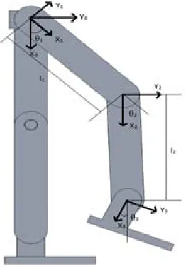
[image:4.612.324.534.422.486.2]In order to control the lower limb exoskeleton, the relationship between joint angles and position of the foot must be identified. The exoskeleton leg is considered to be a Rotational-Rotational-Rotational (RRR) series planar robot due to its movement on Sagittal plane only. Forward kinematics is applied to find the position of the foot if values for the joint angles are given. First, reference frame are assigned to the hip, knee and ankle joint as shown in Figure-2.
Figure-2. Exoskeleton leg with reference frames assigned.
By using the reference frame assigned, the Denavit-Hartenberg(DH) table that represents the translational and rotational relationship between links are constructed as shown in Table-4.
Table-4. Denavit-Hartenberg parameters of the lower limb
exoskeleton.
The position of the foot relative to the base in the x-axis and y-axis can be obtained from the position vector in the transformation matrix. That means an equation of x and y in terms of hip angle and knee angle can be obtained.
After that, inverse kinematics are applied to find the joint angle if given the position of the foot. For inverse kinematics of the leg, the position of the end effector relative to the base serves as the input and the rotation of the hip and knee serve as the output.
Joint torque equation
[image:4.612.121.251.438.626.2] [image:4.612.327.534.560.714.2]The torque required at each joint can be determined by using free body diagrams of different joints. Figure-3, Figure-4, Figure-5 shows the forces acting on hip, knee and ankle joint respectively.
Figure-4. Forces acting at knee joint.
Figure-5. Forces acting at ankle joint.
The torque required to generate by the actuator at each joint can be determined as shown below.
To calculate the torque required for each joint, the mass of the actuators are and the links mass are estimated. The user is targeted to be weighing 100 kg and 1.85 m tall. The body segment parameters of the user can be obtained from (Drillis, Contini and Bluestein, 1964) and (Khan, 2012).
From the calculation, the torque required at hip joint is 47.56 Nm; the torque required at knee joint is 21.68 Nm whereas the torque required at the ankle is 2.10 Nm. Therefore, the motor and drive system should produce more torque than the calculated torque values to lift both the user’s limb and the exoskeleton.
Actuator selection
From the calculations, the torque required at hip, knee and ankle joint are 47.56Nm, 21.68Nm and 2.10Nm respectively to lift the user’s limb for walking. Hence, the motor selected should produce more than the calculated value to be able to lift the exoskeleton and the user’s limbs. In this project, brushless DC motors are selected for their efficiency and longer lifetime compared to other type of motors. Since the exoskeleton requires more torque then speed, gearboxes or reducers are selected to couple with each motor to trade speed for more torque. This will decrease the output speed and increase the output torque significantly.
applied on wearable or exoskeleton robot. The motor and reducer combined to produced 56Nm, 28.9Nm and 12.8Nm at hip, knee and ankle joint respectively. The specification of the motors and reducers are summarized in Table-5 and 6.
Table-5. Specifications of selected motor.
Table-6. Specifications of selected reducers.
Exoskeleton design
The exoskeleton robot is designed using Computer-Aided Design software named SolidWorks. After selecting the actuators, the exoskeleton’s dimension parameters are set according to the objective of this project. The exoskeleton is design according to the anthropomorphic parameters of the human body to make sure that the joints of exoskeleton are concentric with the user’s joints. This will help in improving its compliance to the human body. The anthropomorphic parameters of the limbs are estimated using ratio obtained from (Drillis, Contini and Bluestein, 1964) and (Khan, 2012) to determine the links length of the exoskeleton. Then, an accurate render and design of the parts and links are carried out using SolidWorks with reference to the parameters set.
The exoskeleton is designed to carry an able-bodied and healthy user with a maximum weight of 100kg and height of 185cm. The exoskeleton that includes all the actuator units and links weighs only 6.44kg. It is mainly made up of Aluminium-7075 which is light and strong at the same time. It is considered as a bipedal wearable robot with 3 degree of freedom each limb which allows the hip, knee and ankle joint to be rotated and powered in the Sagittal plane as shown in Figure-7. It consists of thigh link, shank link and foot pad for each limb of the exoskeleton like the human body. All the links are connected together by a pivot joint instead of using the actuator unit as the joint as shown in Figure 6. This design will help in avoiding direct load applied to the motors and reducers which will damage the actuator unit as there are
limitations to its overhung load. Besides that, it will help to shift the load applied by the user’s limb to the pivot joint and thus increasing the lifetime of the actuator unit. Moreover, the pivot joint also limits the rotation of the joint mechanically to avoid any accident caused by the malfunction of the actuators. This is very important precaution to make the exoskeleton safe for the users.
There are special mounts designed to mount the actuators onto the exoskeleton to provide actuation to the joints. The mount not only served as couples the link and the actuator but also serve as the coupling for the motor and reducer. The mounts are also made up of Aluminium-7075 which helps in saving weight. Apart from that, there are adjustable braces to strap onto the user’s limb so that the limb moves with the exoskeleton. The braces are to be covered with Velcro straps for easy and fast fastening action. The exoskeleton’s parts including link and mounts are design using standard thickness of the Aluminium sheet or bar on the market to make it easier and cheaper to be fabricated.
Figure-6. Pivot joint and actuator mount design on the
exoskeleton.
Figure-7. The assembly drawing of the designed
exoskeleton.
Motion analysis
planning is required to for the exoskeleton model to simulate the legs motion in a walking gait. After planning the trajectory, rotary actuators are inserted to each joint of the exoskeleton model in SolidWorks Motion Analysis. Then, the data points of joint angles calculated are inserted into each individual rotary actuator with respect to time as shown in Figure-8. These data points will command the rotary actuator to rotate to desired angles calculated at a specific time and hence perform walking motion. After inserting the data points, the motion simulation of the exoskeleton model is conducted and desired data like torque pattern are recorded. Two tests were conducted to obtain the torque required to perform walking motion.
In the first test, the exoskeleton model was required to perform leg swing movement according to the trajectory planning and obtain the torque value of taking one step. The torque pattern for each joint required to perform the leg swing motion are recorded and observed to verify the ability of the actuator selected to produce enough torque to support the user to take one step. For the second test, the exoskeleton model was required to perform two complete cycles of walking motion to obtain the torque values for a complete walking cycle. The torque pattern for each joint are recorded and analysed to further verify the exoskeleton’s ability to support the user to walk.
RESULT AND DISCUSSION
The torque pattern of each joint recorded are discussed and analysed in this section to examine the selected actuator units’ ability to actuate the user by using SolidWorks Software.
Figure-8. Data points inserted to each joints.
Leg swing motion
This section discusses the toque pattern of each joint obtained from the simulation for the exoskeleton to perform the one leg swing motion. Figure-9 shows the torque pattern of hip joint obtained from the simulation. The torque value recorded for hip joint starts at 12.87 Nm initially and then gradually decreased to -21.32 Nm at 0.88 s and then increased to -20.10 Nm at 1.0 s. The maximum value of torque in terms of magnitude for hip joint
obtained from simulation is 21.32 Nm. This means that the hip joint actuator unit selected is able to support the user to take a step as the torque required does not exceed the maximum continuous torque of actuator unit which is 56 Nm.
Figure-9. Graph of torque against time for hip joint.
Figure-10 shows the torque pattern of knee joint obtained from the simulation. The knee joint torque data obtained from simulation shows a gradual increase from 1.16 Nm at 0s to 10.64 Nm at 0.4s and then gradually decrease to -3.37 Nm. The maximum value for torque values is 9.39Nm. The maximum value for the simulation does not exceed the maximum continuous torque of the knee joint actuator unit selected which is 28.9 Nm. This means that the knee joint actuator units selected are able to support the user to take a step forward.
Figure-10. Graph of torque against time for knee joint.
Figure-11. Graph of torque against time for ankle joint.
In summary, the maximum torque required at all 3 joints to swing the user’s leg does not exceed the maximum continuous torque that can be produced by their respective actuator units. This means that all the actuator units selected are able to swing the leg of the user without any problem.
Two complete cycle walking motion
This section discusses the toque pattern of each joint obtained from the simulation for the exoskeleton to perform two complete cycle walking motion. Different phases in walking are indicated with different coloured region. The region coloured in red represents the stance phase where the foot is in contact with the ground whereas the blue coloured region indicates the swing phase where the foot is off the ground. The red lines indicate the range of maximum continuous torque that can be produce by each respective actuator unit.
Figure-12 and 13 shows the torque pattern for the left and right hip joint respectively. For both of the hip joint, the magnitude of torque values is within the range of 56Nmmost of the time, which is the maximum continuous torque of the hip actuator unit. However, the torque value shows some spikes during the transitions between phases. These spikes are caused by the rapid deceleration of the leg to a brief halt during the transition between phases. This is because the joint requires a large amount of torque to decelerate and then accelerate in the opposite direction during the transition which explains the surge and recover of the torque value. From the Figure-13 and Figure-14, there are multiple spikes shown at 0.67s and 2.00s are which can be caused by a jerk during the deceleration of the joint. This indicates that the transitions were rough which could be caused by the planned trajectory. On the other hand, the singular spike shown at 1.34s indicates a smooth deceleration and acceleration during transition. For a brief moment, the spikes can reach a maximum value of 130Nm which is about two times the maximum continuous torque of the hip actuator unit can produce. Hence, the actuator unit will need to be overdriven in order to mimic the torque pattern of walking motion.
Figure-12. Torque pattern of left hip joint.
Figure-13. Torque pattern of right hip joint.
Figure-14 and 15 shows the torque pattern for the left and right knee joint respectively. For both of the knee joint, the magnitude of torque values is within the range of 28.9Nm most of the time. However, the torque value also shows some spikes during the transitions between phases just like the hip joints. These spikes are caused by the rapid deceleration of the leg to a brief halt during the transition between phases. For a brief moment, the spikes can reach a maximum value of 42Nm which is about 1.5 times the maximum continuous torque of the knee actuator unit can produce. Due to the fact that the knee actuator unit can only supply a maximum continuous torque of 28.9Nm, the actuator unit will need to be overdriven to emulate the walking motion.
Figure-15. Torque pattern of right knee joint.
Figure-16 and 17 shows the torque pattern for the left and right ankle joint respectively. For both of the ankle joint, the magnitude of torque values is within the range of 12.8 Nm all the time even with the torque value spikes during the transitions between phases. These spikes are caused by the rapid deceleration of the leg to a brief halt during the transition between phases. For a brief moment, the spikes can reach a maximum value of 4Nm but it does not exceed the maximum continuous torque that can be produced by the ankle actuator unit. This means that the ankle actuator unit does not need to be overdriven to mimic the torque pattern of ankle joint during walking.
In summary, the actuator units selected are able to actuate the lower limb of the user to walk. However, the hip and knee actuator units will need to be overdriven during transition period between phases in order to mimic the torque pattern of walking
Figure-16: Torque pattern of left ankle joint.
Figure-17. Torque pattern of right ankle joint.
CONCLUSIONS
From the result, the electric powered actuator unit selected for the exoskeleton shows that they are able to swing the user’s limb and actuate the user to walk via overdrive of the actuator unit. In conclusion, the DC motor actuator unit selected from the market can produce enough torque to actuate the user that weighs a maximum of 100kg to walk. For the future work, researchers should focus on the control of the actuator unit and the data acquisition of the sensor to make sure that the exoskeleton designed works as it should.
ACKNOWLEDGEMENTS
We would like to thank the Univesiti Teknikal Malaysia Melaka (UTeM) and Ministry of Education Malaysia (KPM) by supporting a fund for making this project successful.
REFERENCES
[1] Banchadit W., Temram A., Sukwan T.,
Owatchaiyapong P., Suthakorn J. 2012. Design and implementation of a new motorized-mechanical exoskeleton based on CGA Patternized Control. , IEEE International Conference on Robotics and Biomimetics (ROBIO), pp.1668-1673.
[2] Bock T., Linner T., Ikeda W. 2012. Exoskeleton and Humanoid Robotic Technology in Construction and Built Environment. The Future of Humanoid Robots - Research and Applications, pp 111-146.
[4] Drillis R., Contini R., Bluestein M. 1964. Body segment parameters. Artificial limbs, Vol. 8, No. 1, pp 44-66.
[5] Fleischer C., Wege A., Kondak K., Hommel G. Application of EMG signals for controlling exoskeleton robots. Biomed Tech 2006, pp. 314-319.
[6] Herr H. 2009. Exoskeletons and orthoses: classification, design challenges and future directions. Journal of NeuroEngineering and Rehabilitation, pp 1-9.
[7] Hollerbach J. M., Hunter I. W., Ballantyne J. 1992. A comparative analysis of actuator technologies for robotics. The Robotics Review, Vol. 2, pp. 299-342.
[8] Kazerooni H. 2005. Exoskeletons for human power augmentation. IEEE/RSJ International Conference on Intelligent Robots and Systems (IROS 2005), pp.3459-3464.
[9] Kawamoto H., Suwoong Lee, Kanbe S., Sankai Y. 2003. Power assist method for HAL-3 using EMG-based feedback controller. IEEE International Conference on Systems, Man and Cybernetics, 2, pp.1648-1653.
[10]Low K. H., Xiaopeng Liu, Haoyong Yu. 2005. Development of NTU wearable exoskeleton system for assistive technologies. IEEE International Conference Mechatronics and Automation, 2, pp.1099-1106.
[11]Marcheschi S., Salsedo F., Fontana M., Bergamasco M. 2011. Body Extender: Whole body exoskeleton for human power augmentation, IEEE International Conference on Robotics and Automation (ICRA), pp.611-616.
[12]Onen U., Botsali F. M., Kalyoncu M., Tinkir M., Yilmaz N., Sahin Y. 2014. Design and Actuator Selection of a Lower Extremity Exoskeleton., IEEE/ASME Transactions on Mechatronics, Vol. 19, No. 2, pp.623-632.
[13]Pratt G.A., Williamson M.M. 1995. Series elastic actuators. . 'Human Robot Interaction and Cooperative Robots', Proceedings. 1995 IEEE/RSJ International Conference on Intelligent Robots and Systems Vol. 95, No. 1, pp.399-406, 5-9 Aug 1995
[14]Ramsdale R. 2014. Mechanical Components - Potentiometers, Encoders, LVDTs, [online]. Available at:
http://www.engineershandbook.com/Components/posi tionsensors.htm [accessed 28 October 2014]
[15]Rosengrant, B., Kostik, B. (2014). Potentiometers: A Proven Position Sensing Solution that Every Engineer Needs to Consider in Modern Designs, [online].
Available at:
http://www.sensorsmag.com/sensors/position- presence-proximity/potentiometers-a-proven-position-sensing-solution-every-engi-9038 [accessed 28 October 2014]
[16]Sanz-Merodio D., Cestari M., Arevalo J.C., Garcia E. 2012. A lower-limb exoskeleton for gait assistance in quadriplegia," IEEE International Conference on Robotics and Biomimetics (ROBIO), pp.122-127.
[17]Stopforth R. 2012. Customizable Rehabilitation Lower Limb Exoskeleton System. Int J Adv Robotic Sy, Vol. 9, No. 152.
[18]Tawakal Hasnain Baluch, A. M., Iqbal J., Izhar U. and Khan U. S. 2012. Kinematic and Dynamic Analysis of a Lower Limb Exoskeleton. World Academy of Science, Engineering and Technology, 6, pp. 812-816.
[19]Walsh C.J., Paluska D., Pasch K., Grand W., Valiente, A., Herr H. 2006. Development of a lightweight, under actuated exoskeleton for load-carrying augmentation. Proceedings IEEE International Conference on Robotics and Automation, 2006. ICRA 2006, pp.3485-3491.
[20]Walsh C. J. 2006. Biomimetic design of an under-actuated leg exoskeleton for load-carrying augmentation. PhD. dissertation, Dept. of Mech. Eng, Massachusetts Institute of Technology, Cambridge, MA.
[21]Xianggang Zhang, Zenghe Xiang, Qingxia Lin, Qifang Zhou. 2013. The design and development of a lower limbs rehabilitation exoskeleton suit. ICME International Conference on Complex Medical Engineering (CME), pp.307-312, 25-28.
[22]Zoss A. B., Kazerooni H., Chu A. 2006. Biomechanical design of the Berkeley lower extremity exoskeleton (BLEEX). IEEE/ASME Transactions on Mechatronics, Vol. 11, No. 2, pp.128-138.