Matlab Simulation on 3ph Inverter for Distributed Generation System:
Adaptive Voltage Control and P-Q Control of the System
Pankaj Singh
1Dr. A. K. Kori
21
Research Scholar
2Professor
1,2
Department of Electrical Engineering
1,2
JEC, Jabalpur (M.P.) India
Abstract— This paper present a robust adaptive voltage control of three-phase voltage source inverter for a distributed generation system using harmonic filter. Proposed adaptive voltage control technique combines an adaption control term, harmonic filter and a state feedback control term. In addition, the proposed algorithm is depend upon the existing work, so we are incorporating the harmonic filter, by using of these filter we can analyze and measure the voltage changes accordingly existing research. In this paper, also we can see the graph for the active ad reactive power for the three phase inverter source. The simulation and experimental results are presented under the parameter uncertainties and are compared to the performances of the corresponding adaptive voltage controller to proposed control schematic filter using harm. Key words: Active and Reactive Power, Harmonic Filter, Simulation
I. INTRODUCTION
In recent years, eco-friendly distributed generation systems (DGS) such as wind turbines, solar cells, and fuel cells are dramatically growing because they can fulfill the increasing demand of electric power due to the rapid growth of the economy and strict environmental regulations regarding greenhouse gas emissions [1]–[8]. Generally, the DGSs are interconnected in parallel with the electric utility grid and provide maximum electric power to the grid. However, there are some areas (e.g., remote islands or villages) where the connection to the grid is expensive or impractical and then small scaled standalone DGSs are the only efficient and economical options. In such DGSs, depending on consumers’ power demand, there are situations where some DGSs operate in parallel [9]–[11] or independently [12]– [14]. In either case, a stable operation of each DGS unit is as important as the stability of the parallel operating DGSs in which the proper load sharing of each unit is one of main research issues since the voltage controller is commonly used in a single DGS unit or multiple DGS units.
For this reason, the voltage controller design for a single DGS unit, which can guarantee a good voltage regulation under unbalanced and nonlinear loads, is an interesting topic in the field of the DGSs control. For the purpose of improving the quality of inverter output voltage, many researchers are working on designing the controllers for dc–ac power converters. In [15], a control scheme based on the transfer function of the nominal plant is proposed for an electronically coupled DG unit in an islanded mode. This control method is suitable for a pre-specified and balanced load condition, but cannot cover the large load variations. In [16], a robust controller is developed for balanced and unbalanced systems, which considers the uncertainties of the
load parameters. However, nonlinear load is not fully addressed.
[image:1.595.308.547.319.410.2]In [20], a robust servomechanism voltage controller and a discrete-time sliding mode current controller are presented to control a single distributed generation unit in a standalone mode which can operate well under a sudden load change, an unbalanced load, and a nonlinear load. However, the controller provided in [20] is quite complicated. In [21], a voltage and frequency control strategy based on a discrete-time mathematical model is proposed for the islanded operation of dispatch able electronically coupled distributed-resource units. The method [21] can achieve good voltage regulation under various load types.
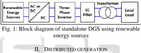
Fig. 1: Block diagram of standalone DGS using renewable energy sources
II. DISTRIBUTED GENERATION
Distributed generation, also called on-site generation, dispersed generation, embedded generation, decentralized generation, decentralized energy or distributed energy generates electricity from many small energy sources. Currently, industrial countries generate most of their electricity in large centralized facilities, such as fossil fuel (coal, gas powered) nuclear or hydropower plants.
The low pollution permits the plants to be near enough to a city to be used for district heating and cooling. Distributed generation is another approach. It reduces the amount of energy lost in transmitting electricity because the electricity is generated very near where it is used, perhaps even in the same building. This also reduces the size and number of power lines that must be constructed.
Distributed energy resource (DER) systems are small-scale power generation technologies (typically in the range of 3 kW to 10,000 kW) used to provide an alternative to or an enhancement of the traditional electric power system. The usual problems with distributed generators are their high costs.
III. PROBLEM STATEMENTS
DES technologies have very different issues compared with traditional centralized power sources. For example, they are applied to the mains or the loads with voltage of 480 volts or less; and require power converters and different strategies of control and dispatch. All of these energy technologies provide a DC output which requires power electronic interfaces with the distribution power networks and its loads. In most cases the conversion is performed by using a voltage source inverter (VSI) with a possibility of pulse width modulation (PWM) that provides fast regulation for voltage magnitude.
Power electronic interfaces introduce new control issues, but at the same time, new possibilities. For example, a system which consists of micro-generators and storage devices could be designed to operate in both an autonomous mode and connected to the power grid. One large class of problems is related to the fact that the power sources such as micro turbines and fuel cell have slow response and their inertia is much less. It must be remembered that the current power systems have storage in generators’ inertia, and this may result in a slight reduction in system frequency.
As these generators become more compact, the need to link them to lower network voltage is significantly increasing. However, without any medium voltage networks adaptation, this fast expansion can affect the quality of supply as well as the public and equipment safety because distribution networks have not been designed to connect a significant amount of generation. Therefore, a new voltage control system to facilitate the connection of distributed generation resources to distribution networks should be developed. In many cases there are also major technical barriers to operating independently in a standalone AC system, or to connecting small generation systems to the electrical distribution network with lower voltage, and the recent research issues includes:
1) Control strategy to facilitate the connection of distributed generation resources to distribution networks using the harmonic filter.
2) Inverter control based on only local information. 3) Synchronization with the utility mains.
4) Compensation of the reactive power and higher harmonic components.
5) Power Factor Correction. 6) System protection.
7) Reliability of communication. 8) Requirements of the customer.
9) active and reactive power measurement
Hence, future research work will focus on solving the above issues so that DES with more advantages compared with tradition large power plants can thrive in electric power industry.
The main goals which should be achieved will thus be: to increase the network connection capacity by allowing more consumers and producer customers connection without creating new reinforcement costs, to enhance the reliability of the systems by the protections, to improve the overall quality of supply with a best voltage control.
IV. MODELING AND CONTROL OF INVERTER INTERFACED DG
UNITS
Basically each DG unit may have DC type or rectified generation unit (Fuel cell, solar cell, wind turbine, micro turbine…), storage devices, DC-DC converter, DC-AC inverter, filter, and transformer for connecting to loads or utility in order to exchange power. Model and dynamic of each of this part may have influence in system operation. But here for simplification it is considered that DC side of the units has sufficient storage and considered as a constant DC source. Hence only DC-AC inverter modeling and control investigated in this paper.
[image:2.595.308.551.278.426.2]A circuit model of a three-phase DC to AC inverter with LC output filter is further described in Figure As shown in the figure, the system consists of a DC voltage source (Vdc), a three- phase PWM inverter, an output filter (Lf and C with considering parasitic resistance of filter- Rf). Sometimes a transformer may be used for stepping up the output voltage and hence Lf can be transformer inductance.
Fig. 2: PWM inverter diagram
There are two ways for controlling an inverter in a distributed generation system
A. PQ Inverter Control
This type of control is adopted when the DG unit system is connected to an external grid or to an island of loads and more generators. In this situation, the variables controlled by the inverter are the active and reactive power injected into the grid, which have to follow the set points Pref and Qref, respectively. These set points can be chosen by the customer or by a central controller. The PQ control of an inverter can be performed using a current control technique in qd reference frame which the inverter current is controlled in amplitude and phase to meet the desired set-points of active and reactive power.
[image:2.595.308.549.555.689.2]B. Vf Inverter Control
Fig. 4: Vf Control scheme of inverter
This controller has to act on the inverter whenever the system is in stand-alone mode of operation. In fact in this case it must regulate the voltage value at a reference bus bar and the frequency of the whole grid. A regulators work in order to keep the measured voltages upon the set points. Moreover the frequency is imposed through the modulating signals of the inverter PWM control by mean of an oscillator. A simple PI controller can regulate bus voltage in reference value with getting feedback of real bus voltage. Figure outlines this control strategy. In this case it is obvious that the DG unit should have storage device in order to regulate the power and voltage.
C. Single-Phase Voltage Source Converter
Single-phase voltage source converter can be found as half-bridge and full-half-bridge topologies. Although the power range they cover is the low one, they are widely used in power supplies, single-phase UPSs, and currently to form elaborate high-power static power topologies, such as for instance, the multicell configurations that are reviewed
V. MODELING OF PROPOSED THEORY SYSTEM MODEL AND
CONTROL STRATEGY
A. State-Space Model of a Load-Side Inverter
Fig. 5 describes a block diagram of a standalone DGS using renewable energy sources which are wind turbines, solar cells, fuel cells, etc. As depicted in Fig. 5.1, the DGS is divided into six parts: an energy source, an ac–dc power converter (wind turbines) or a dc–dc boost converter (solar cells or fuel cells),a three-phase dc–ac inverter, an LC output filter, an isolation transformer, and a local load. In this paper, a renewable energy source and an AC–DC power converter or a dc–dc boost converter can be replaced by a stiff dc voltage source (Vdc) because this paper focuses on designing a robust adaptive voltage controller under various types of loads such as balanced load, unbalanced load, and nonlinear load. Also, this representation can be acceptable because the front converter (i.e., an AC–DC power converter or a dc–dc boost converter) can rapidly recover the reduced\ dc-link voltage when a heavy load is suddenly applied. The DG energy sources usually work together with energy storage devices (e.g., batteries, flywheels, etc.) in
[image:3.595.312.539.88.199.2]assuming that the customers need a low voltage ac source (below 600 V) which the DGSs using renewable energy sources can generate without the help of the transformer.
Fig. 5: Schetamatic diagrame of three phase dc to ac inverter with an LC filter
Fig. 5 shows a schematic diagram of a three-phase dc–ac inverter with an LC filter in a standalone application.
Fig. 6: Block diagram of the Existing adaptive voltage controller
B. Control Strategy Verifications
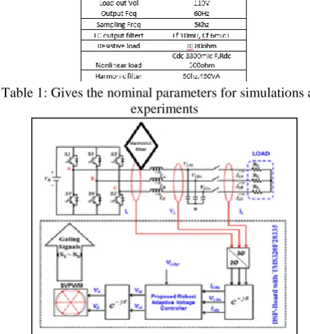
[image:3.595.310.533.470.710.2]In this paper, a prototype 450VA DG unit is considered to implement the proposed control algorithm. Table I gives the nominal parameters for simulations and experiments.
Table 1: Gives the nominal parameters for simulations and experiments
Fig. 8: Circuir Diagrame of non linear load
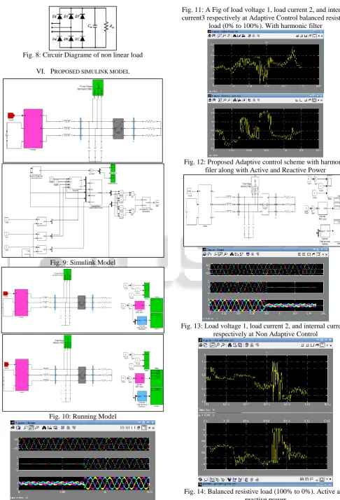
VI. PROPOSED SIMULINK MODEL
Fig. 9: Simulink Model
Fig. 10: Running Model
Fig. 11: A Fig of load voltage 1, load current 2, and internal current3 respectively at Adaptive Control balanced resistive
load (0% to 100%). With harmonic filter
Fig. 12: Proposed Adaptive control scheme with harmonic filer along with Active and Reactive Power
[image:4.595.48.535.46.761.2]Fig. 13: Load voltage 1, load current 2, and internal current3 respectively at Non Adaptive Control
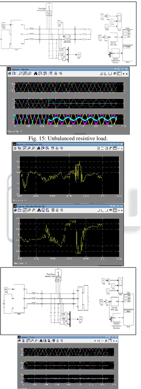
Fig. 15: Unbalanced resistive load.
Fig. 17: Simulation results of the proposed adaptive voltage controller with150% uncertainties of system parameters (k1 to k4) under four different conditions. (a) Balanced resistive load (0% to 100%). (b) Balanced resistive load (100% to 0%). (c) Unbalanced resistive load. (d) Nonlinear load (i.e.,
[image:5.595.323.533.125.262.2]a capacitive output load with a high crest factor of 2.25:1).
Table 2: Summary of simulation result in Steady state Analysis with harmonic filter
As illustrated in Fig. 17, the inverter phase currents (Ii), load output voltages (VL), and load phase currents (IL) are measured and then are transformed to the quantities (Iidq, VLdq, ILdq) in the synchronously rotatingd–q reference frame, respectively. In this paper, a space-vector PWM technique is chosen to implement the control inputs (Vid and Viq)that the proposed voltage controller generates in real time.In the paper, simulations and experiments are carried out to verify the effectiveness of the proposed adaptive control algorithm under the following four conditions:
Balanced load (0%→100%): The balanced resistive load is instantaneously applied to the inverter output terminals.
Balanced load (100%→0%): The balanced resistive load is instantaneously removed from the inverter output terminals.
Unbalanced load: The unbalanced resistive load is connected to the inverter output terminals, i.e., only phaseC is opened.
Nonlinear load: A three-phase full-bridge diode rectifier is connected to the inverter output terminals. As shown in Fig. 5.5, it is also connected in parallel with a capacitor (Cdc)and a resistor(Rdc), and the nonlinear load has a crest factor of 2.25:1.
VII. CONCLUSION
REFERENCES
[1] H. K. Kang, C. H. Yoo, I. Y. Chung, D. J. Won, and S. I. Moon, ―Intelligent coordination method of multiple distributed resources for harmonic current compensation in a microgrid,‖J. Elect. Eng. Technol., vol. 7, no. 6, pp. 834–844, Nov. 2012.
[2] M. Liserre, T. Sauter, and J. Y. Hung, ―Future energy systems: Integrating renewable energy sources into the smart power grid through industrial electronics,‖ IEEE Ind. Electron. Mag., vol. 4, no. 1, pp. 18–37, Mar. 2010. [3] S. Bogosyan, ―Recent advances in renewable energy employment,‖ IEEE Ind. Electron. Mag., vol. 3, no. 3, pp. 54–55, Sep. 2009.
[4] B. C. Sung, S. H. Lee, J. W. Park, and A. P. S. Meliopoulos, ―Adaptive protection algorithm for overcurrent relay in distribution system with DG,‖J. Elect. Eng. Technol., vol. 8, no. 5, pp. 1002–1011, Sep. 2013.
[5] M. Y. Kim, Y. U. Song, and K. H. Kim, ―The advanced voltage regulation method for ULTC in distribution systems with DG,‖ J. Elect. Eng. Technol., vol. 8, no. 4, pp. 737–743, Jul. 2013.
[6] L. Gertmar, L. Liljestrand, and H. Lendenmann, ―Wind energy powers that-be successor generation in globalization,‖ IEEE Trans. Energy Conver., vol. 22, no. 1, pp. 13–18, Mar. 2007.
[7] A. Q. Huang, M. L. Crow, G. T. Heydt, J. P. Zheng, and S. J. Dale, ―The future renewable electric energy delivery and management (FREEDM) system: The energy internet,‖ Proc. IEEE, vol. 99, no. 1, pp. 133– 148, Jan. 2011.
[8] A. Mokhtarpour, H. A. Shayanfar, M. Bathaee, and M. R. Banaei, ―Control of a single phase unified power quality conditioner-distributed generation based input output feedback linearization,‖J. Elect. Eng. Technol., vol. 8, no. 6, pp. 1352–1364, Nov. 2013.
[9] M. N. Marwali, J. W. Jung, and A. Keyhani, ―Stability analysis of load sharing control for distributed generation systems,‖IEEE Trans. Energy Convers., vol. 22, no. 3, pp. 737–745, Sep. 2007.
[10]Y. Zhang, M. Yu, F. Liu, and Y. Kang, ―Instantaneous current-sharing control strategy for parallel operation of UPS modules using virtual impedance,‖ IEEE Trans. Power Electron., vol. 28, no. 1, pp. 432–440, Jan. 2013. [11]J. He and Y. W. Li, ―An enhanced microgrid load
demand sharing strategy,‖IEEE Trans. Power Electron., vol. 27, no. 9, pp. 3984–3995, Sep. 2012.
[12]G. K. Kasal and B. Singh, ―Voltage and frequency controllers for an asynchronous generator-based isolated wind energy conversion system,‖ IEEE Trans. Energy Convers., vol. 26, no. 2, pp. 402–416, Jun. 2011.
[13]I. Vechiu, O. Curea, and H. Camblong, ―Transient operation of a four-leg inverter for autonomous applications with unbalanced load,‖IEEE Trans. Power Electron., vol. 25, no. 2, pp. 399–407, Feb. 2010. [14]H. Nian and R. Zeng, ―Improved control strategy for
stand-alone distributed generation system under unbalanced and non-linear loads,‖ IET Renew. Power Gener., vol. 5, no. 5, pp. 323–331, Sep. 2011.
[15]H. Karimi, H. Nikkhajoei, and R. Iravani, ―Control of an electronically coupled distributed resource unit
subsequent to an islanding event,‖ IEEE Trans. Power Del., vol. 23, no. 1, pp. 493–501, Jan. 2008.
[16]H. Karimi, A. Yazdani, and R. Iravani, ―Robust control of an autonomous four-wire electronically-coupled distributed generation unit,‖IEEE Trans. Power Del., vol. 26, no. 1, pp. 455–466, Jan. 2011.
[17]G. Escobar, A. A. Valdez, J. Leyva-Ramos, and P. Mattavelli, ―Repetitive based controller for a UPS inverter to compensate unbalance and harmonic distortion,‖ IEEE Trans. Ind. Electron., vol. 54, no. 1, pp. 504–510, Feb. 2007.
[18]A. Yazdani, ―Control of an islanded distributed energy resource unit with load compensating feed-forward,‖ in Proc. IEEE Power Eng. Soc. Gen. Meet., Pittsburgh, PA, USA, Jul. 2008, pp. 1–7.
[19]S. Dasgupta, S. K. Sahoo, and S. K. Panda, ―Single-phase inverter control techniques for interfacing renewable energy sources with microgrid—Part I: Parallel-connected inverter topology with active and reactive power flow control along with grid current shaping,‖ IEEE Trans. Power Electron., vol. 26, no. 3, pp. 717–731, Mar. 2011.
[20]M. Dai, M. N. Marwali, J. W. Jung, and A. Keyhani, ―A three-phase fourwire inverter control technique for a single distributed generation unit in island mode,‖IEEE Trans. Power Electron., vol. 23, no. 1, pp. 322–331, Jan. 2008.
[21]M. B. Delghavi and A. Yazdani, ―Islanded-mode control of electronically coupled distributed-resource units under unbalanced and nonlinear load conditions,‖ IEEE Trans. Power Del., vol. 26, no. 2, pp. 661–673, Apr. 2011.