A Study of the Ultimate Pile Load Capacity Calculation Methods for
Cohesion less Soil
Smilu Kalarikkal
1Sunil Kumar K.
21
M.Tech
Student
2Head of Department
2
Department of Civil Engineering
1,2
Sahyadri College of Engineering & Management, Mangalore, Karnataka, India
Abstract— Numerous techniques are available for finding the ultimate load carrying capacity of piles which includes the static methods, dynamic methods, in-situ penetration tests and the pile load tests. Of these, the static methods, in-situ penetration tests and the pile load tests gives the most reliable results with the pile load tests being the most prevalent of all three. Although there are a number of methods to analytically find out the load carrying capacity, these are often based partly on soil and rock mechanics and partly on empirical methods based on experiments. In this study, the different methods have been analyzed and worked out on various case studies to make a comparison between the results obtained from the different analytical methods to check for the variation in the obtained values and arrive at the methods which gives the most favourable results for obtaining the ultimate bearing capacity and also understand the best approaches for such analytical procedures.
Key words: Ultimate Pile Load Capacity, Shaft Resistance, Point Resistance
I. INTRODUCTION
A pile carries the load acting on it in the form of frictional resistance contributed by the frictional strength of the soil present along the pile shaft coupled with the pile-soil interactions and by the end bearing resistance attained from the bearing capacity of the hard and less compressible stratum onto which the pile is embedded. Depending on the sub surface conditions in the pile embedment, the behavior of pile also shows considerable variation under the action of load and the factors contributing the strength in each of the above conditions also vary respectively. However it can be seen that the effective over burden pressure and the corresponding bearing capacity factors are the most crucial factors for determining pile capacity in case of piles founded on non-cohesive soils and on the other hand, the values of undrained cohesion and adhesion factors are the deciding factors of ultimate pile capacity determination in the case of cohesive soils.
This paper studies the variation of ultimate pile load capacities as obtained from the various static analysis methods for piles in non-cohesive soils and the different underlying approaches considered for estimating the ultimate capacities. The results of the study has been arrived at by considering general and real time case studies of bored cast in-situ concrete piles in non- cohesive soils. For non-cohesive soils, the calculation of ultimate pile load capacity takes into account the characteristics of pile behavior such as the concept of critical depth, where in a linear increase of frictional resistance takes place till the critical depth of pile depending on the internal friction angle as 15d for ϕ ≤ 30o and
20d for ϕ ≥ 40o, where d is the diameter of the pile. The
methods considered for the study have been further suited to
friction and end bearing piles and they have been compared with each other to draw conclusion on the suitability of the approach and the method on the various ground and piling conditions. The methods have been studied and the various parameters contributing to the calculations have been examined to arrive at the results and comparisons. Several comparisons have been made in this regard on the light of which the variation in the values obtained from the various methods when compared with each other and the results prove useful in finding the suitability of the particular methods to the ground conditions and the adoptability and accuracy of the same. This data could further be used to derive correlations between the values obtained from the soil reports, standard penetration test data and other relevant parameters.
II. METHODOLOGY
The calculation of load carrying capacity by static method uses the principle that the ultimate load carrying capacity of pile is the sum of load carrying capacity of the shaft of pile in friction in cohessionless soils or adhesion in case of cohesive soils. Therefore the ultimate pile load capacity Qu is obtained
as,
Qu = Qb + Qf - Wp
Where,
Qb = base (or tip or point) resistance of pile.
Qf = shaft resistance due to adhesion of friction between the
pile shaft and soil. Wp = weight of pile.
Here the calculation of quantities Qb and Qf varies
from method to method. However in all these approaches pile capacities are basically estimated by the characteristics of soil. The pile capacity is further depend on many factors such as the material and shape of pile, type of soil condition, penetration or installation techniques and so on. Due to the influence of these factors the pile capacities obtained based on these analytical approaches may vary from the values of pile capacity obtained from the field load tests. Hence the variation of about 20% may be considered as permissible change of values.
A. Methods 1) IS Code Method
The Indian Standard Code gives the load carrying capacity of piles through static analysis in
IS 2911(Part 1/Sec 1)-For driven cast in-situ concrete piles.
IS 2911(Part 1/Sec 2)-For bored cast in-situ concrete piles.
IS 2911(Part 1/Sec 3)-For driven pre cast concrete piles. IS 2911(Part 1/Sec 4)-For precast concrete piles in
According to Annex B, clause 6.3.1.1 and 6.3.2, The ultimate pile load capacity (Qu ) in kN is,
Qu=Ap (0.5 Dγ Nγ + PD Nq)+ ∑ni=1Ki PDi tanδi Asi
Where,
Ap = cross sectional area of the pile tip, in m2.
D= diameter of the pile shaft, in m.
γ=effective unit weight of the soil at pile tip, in kN/m3.
Nγ , Nq =bearing capacity factors depending upon the
angle of internal friction, φ at the pile tip.
PD = effective over burden pressure at the pile tip in
kN/m3.
∑n =
i=1 summation for layers 1 to n in which pile is installed and which contribute to positive skin friction. Ki = coefficient of earth pressure applicable for the ith
layer.
PDi =effective over burden pressure for the ith layer, in
kN/m2.
δi= angle of wall friction between pile and soil for the ith
layer.
Asi= surface area of the pile shaft in the ith layer, in m2.
2) Janbu’s Method
The equation for bearing capacity suggested by Janbu (1976) is as given below,
Qb = (c Nc* + qo′Nq∗ ) Ab …Janbu gives the formula for
determining Qb
(Qu= Qb+ Qs = (c Nc* + qo′Nq∗ ) Ab + fs As)
Where,
Nq∗ = (tanΦ + √1 + tan2ϕ )2e2φ tan ϕ
Nq∗ = bearing capacity factor dependent on the angle, φ. φ = angle varies from 60o in soft compressible soil to
105o in dense sand, obtained from Janbu’s Chart.
3) Coyle & Castello’s Method
Coyle and Castello (1981) proposed a method to estimate the ultimate pile load capacity based on their results of pile load tests carried out on instrumented pile, and ascertained separately the point load and friction load from the total load. On the bases of their study the following formula was proposed finding out the ultimate pile load capacity.
Qu = qo′Nq∗ Ab + As q0 Ks̅̅̅tanδ
where,
qo′ = effective overburden pressure at the base level of the pile.
Nq∗ = bearing capacity factor, obtained from the Coyle and Castello’s chart.
q0=Average effective overburden pressure.
δ=Angle of wall friction=0.8ϕ
Ks is obtained from the Coyle and Castello’s Table.
4) Vlerendeel’s Equation
Vlerendeel gave an equation for calculating the ultimate load capacity specifically for friction piles with the total load capacity being equal to the ultimate shaft resistance of the pile. The equation for the ultimate load capacity by Vlerendeel is shown below,
Qup= Qsp=0.5 f γ π D Lf2 tan2(45+
ϕ
2 ) Where,
f=coefficient of friction. Lf=embedded length.
Note:
*f=0.33 for concrete & timber piles. * f=0.25 for smooth piles.
5) Based On Draft Canadian Manual on Foundation Engineering
The draft Canadian manual on foundation engineering recommends the following formula for calculation of ultimate pile load capacity as shaft resistance,
Qsp=
f
2π D L; for L<= zc Qsp=
f
2π D zc +f π D (L- zc );for L>= zc Where,
L=depth of the pile.
zc =depth to centre of gravity of embedded portion of pile
measured below the top of corresponding layer. 6) Irlend’s Method
The formula based on Irlend’s method is applicable for friction piles in cohesionless soils. The formula was arrived based on pull-out test conducted on piles. The formula is, Qup= Qsp= π D Lf (γ zc +q) Kδtanϕ
Where,
Lf=length of embedment for pile in any stratum, total
length for a uniform pile deposit. γ=unit weight of soil.
zc =depth to centre of gravity of embedded portion of pile
measured below the top of corresponding layer. q=surcharge load.
Kδ = 1 to 2 (Concrete piles).
7) Benebenq’s Method
This equation was proposed initially for driven piles in cohessionless soils but the same can also be applied for calculating the ultimate capacity for bored piles.
Qup=
mγD2L fKp2
8sinθ + mγDLf2
2 Kptanϕ Where,
m=ratio of perimeter to diameter of pile i.e., π. Kp=passive earth pressure coefficient i.e., tan2(45+
ϕ 2 ) θ= one half of angle of pile points
8) Meyerhof’s SPT Method
The IS code gives the relation between the standard penetration resistance values with the pile capacity as suggested by Meyerhof. The ultimate resistance of pile in kN is,
Qu= 40 N (
Lb
D ) Ap + N̅As
0.50…..for driven piles. Qu= 30 N (
Lb D ) Ap +
N̅As
0.50……for non plastic silt or very fine sand(driven piles)
Qu= 13 N (
Lb
D ) Ap + N̅As
0.50……for bored piles. Qu= 10 N (
Lb D ) Ap +
N̅As
0.50….. for non plastic silt or very fine sand(bored piles)
where,
Qu =Ultimate total load in kN.
N = Average N value at pile tip.
N̅ = Average N value along the pile shaft.
Lb= Length of pile penetration in the bearing strata, in m. Ap =Cross sectional area of the pile tip, in m2.
As=Surface area of pile shaft, in m2.
B. Case studies
1) General Case Study – 1
Types of pile Bored cast in-situ Diameter of pile 600mm
Length of pile 20m Unit weight of soil 18kN/m3
Table 1: 2) Results
Method Qb (kN)
Qf
(kN) Qu (kN) IS Code Method 950.14 3794.56 4744.70 Janbu’s Method 1140.35 3794.56 4934.91 Coyle and Castello’s
Method 1373.92 2038.85 3412.77 Vlerendeel’s Equation - 6717.98 6717.98 Draft Canadian Manual
Method - 2748.26 2748.26
Irlend’s Method - 5876.70 5876.70 Benebenq’s Method - - 12211.46
Meyerhof’s SPT
Method 2450.06 1507.6 3957.66 Table 2:
Fig. 1:
C. Case Study – 2
Type of structure Commercial building Project Name Gaur city mall
Location Ghaziabad, Uttar Pradesh Types of pile Bored cast in-situ Diameter of pile 1000mm
Length of pile 20m
Unit weight of soil 18kN/m3
Table 3: 1) Results
Method Qb (kN) Qf (kN) Qu (kN)
IS Code Method 17975.52 3749.37 21724.89 Janbu’s Method 12365.16 3749.37 16114.53 Coyle and Castello’s
Method 12717 6994.56 19711.56 Vlerendeel’s
Equation - 14375.88 14375.88 Draft Canadian
Manual Method - 13964.69 13964.69 Irlend’s Method - 12325 12325
Benebenq’s Method - - 33730.94
Meyerhof’s SPT
[image:3.595.46.552.64.744.2]Method 11429.6 4171.92 15601.52 Table 4:
Fig. 2:
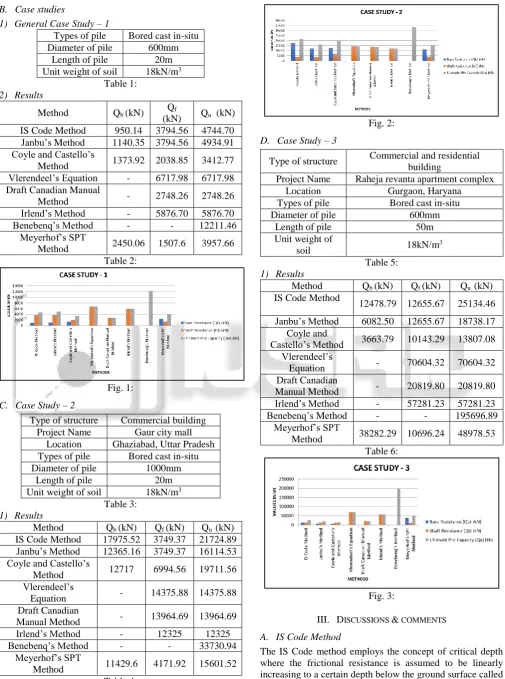
D. Case Study – 3
Type of structure Commercial and residential building
Project Name Raheja revanta apartment complex Location Gurgaon, Haryana Types of pile Bored cast in-situ
Diameter of pile 600mm
Length of pile 50m
Unit weight of
soil 18kN/m
3
Table 5: 1) Results
Method Qb (kN) Qf (kN) Qu (kN)
IS Code Method
12478.79 12655.67 25134.46
Janbu’s Method 6082.50 12655.67 18738.17 Coyle and
Castello’s Method 3663.79 10143.29 13807.08 Vlerendeel’s
Equation - 70604.32 70604.32 Draft Canadian
Manual Method - 20819.80 20819.80 Irlend’s Method - 57281.23 57281.23
Benebenq’s Method - - 195696.89
Meyerhof’s SPT
Method 38282.29 10696.24 48978.53 Table 6:
Fig. 3:
III. DISCUSSIONS & COMMENTS
A. IS Code Method
contributed by the soil system seems to play the most crucial role in determining the capacities coupled with the bearing capacity factors as suggested by the codal specifications. This method allows the prediction of ultimate pile capacity as both base resistance and shaft resistance separately and hence proves advantageous in determining the contribution of the individual resistances.
The results from the case studies shows that there is a fairly good prediction of the end bearing and frictional resistances by these methods and the values are mostly within the range of values as from the majority of the other methods in consideration for the study. By separately considering individual layers below the soil there is also a fairly accurate judgement of the frictional resistance contributed by the soil to the pile system.
B. Janbu’s Method
This method gives the formula for the prediction of the end bearing resistance based on the effective over burden pressure and the bearing capacity factor as suggested by Janbu. The determination of the bearing capacity factor is not just dependent on the angle of internal friction but also relies on an angle which varies with respect to the physical properties of the soil that comprises the pile-soil system.
From the case studies it can be seen that the base resistance as suggested by Janbu has been slightly in the lower range of values obtained comparing the other methods. However, the difficulties in obtaining a value of ψ for different stations at the base level and also the settlement needed at pile base for the full development of plastic zone create uncertainties in this procedure and make it difficult to validate this method.
C. Coyle & Castello’s Method
According to this method, the effective over burden pressure is the most important parameter that determines both the frictional resistance as well as the base resistance. The bearing capacity factor here is determined from the Coyle and Castello’s chart and is dependent on the L/d ratio of the pile as well as the angle of internal friction and the value of it obtained from this method lies in much conformity to that obtained from the IS method and the Janbu’s mehod.
From the case studies, it can be seen that the values of pile capacities obtained here has been neither too high nor too low in comparison to the rest of the methods but always within the average range. Hence, this method may be used for determining pile capacities quite effectively by moderately estimating the values.
D. Vlerendeel’s Equation
This method is used for estimating the ultimate pile capacity by considering the pile as friction pile. The pile dimensions along with the lateral earth pressure coefficient are the major parameters involves in determining the frictional capacity. The coefficient of friction used in this method has been defined for the depending on the material of pile.
The case studies shows that the frictional capacity as obtained from this method is an overestimated value compared to the other methods in consideration by always providing the highest value of shaft resistance from all the methods.
E. Based on Draft Canadian Manual on Foundation Engineering
This method gives the ultimate pile capacity considering the pile as friction pile and with shaft resistance being the ultimate resistance. Here, the ultimate value of skin friction along the pile length is related to the ultimate point resistance and a coefficient αϕ obtained from the angle of internal
friction of the soil layer found at the critical depth.
The results from the case studies shows that the values of frictional resistance obtained by this method is higher compared to the other methods and would require a higher value of safety factor to be employed to rightly predict the ultimate load capacity without over estimation.
F. Irlend’s Method
This method is also applicable in case of friction piles and is dependent on parameters such as lateral earth pressure coefficient, pile and soil characteristics. The possibility of having a surcharge load is also considered in this method and the parameters are assessed at the depth of centre of gravity of embedded portion of pile measured below the top of the corresponding layer.
The case studies shows a fairly high range of values as compared to those obtained from the other methods analysed for the study and hence isn’t quite reliable for predicting the ultimate pile capacities judiciously.
G. Benebenq’s Method
This method gives the direct value of ultimate pile load capacity and hence cannot be used for determining the value of base resistance and shaft resistance separately. The formula is based on parameters such as pile dimension, angle of internal friction, one half of angle of pile points and so on. However, the results from the case studies reveal that the value of ultimate load capacity is highly over estimated in this method therefore demands a very high factor of safety to be used for finding the actual allowable capacity. Thus, it can be concluded that this is the least preferred method for prediction of ultimate pile load capacity.
H. Meyerhof’s SPT Method
This method is based on the data obtained from standard penetration tests and can be used for predicting the ultimate pile capacity as the sum of the base resistance and frictional resistance. The blow counts obtained from the standard penetration tests can also be used for obtaining suitable correlations for predicting the various soil characteristics effectively.
The case studies reveal that the values of pile load capacities obtained by this method is in much conformity to that obtained from the static analysis methods and enables a fairly good prediction of ultimate load carrying capacity which is always well within the range of average ultimate capacities obtained in overall comparison.
Preference
No. Method
1 Is Code Method
2 Meyerhof’s SPT Method
3 Coyle And Castello’s Method
5 Irlend’s Method
6 Janbu’s Method
7 Vlerendeel’s Equation
8 Benebenq’s Method
Table 7:
REFERENCES
[1] Bogumil Wrana, “Pile Load Capacity – Calculation Methods Studia Geotechnica Mechanica, Vol. 37, No. 4, 2015, DOI: 10.1515/sgem-2015-0048 [2] Fatema Sultana1, Nusrat Khanum Zinia2, Farjana Akter3
& Md. Motiur Rahman Khan4, “Testing and design of a piled foundation Project”, Journal of the Southeast Asian Geotechnical Society (2009) 40(3) 129-137.
[3] B. Manjula Devi11, Chore H.S2, V.A.Sawant3, “Analysis of Laterally Loaded Pile Groups”, IOSR Journal of Civil Engineering (IOSR-JMCE), ISSN: 2278-0661, ISBN: 2278-8727, PP: 60-64.
[4] Thadapaneni Kanakeswararao1, B.Ganesh2 “Analysis of Pile Foundation Subjected to Lateral and Vertical Loads”, International Journal of Engineering Trends and Technology (IJETT) – Volume-46 Number-2 -April 2017 ISSN: 2231-5381.
[5] IS 2911: PART 1: Sec 1: 1979 Driven cast in – situ concrete piles.
[6] IS 2911: PART 1: Sec 2: 1979 Bored cast in – situ concrete piles.