DESIGN AND PERFORMANCE EVALUATION OF ON CHIP
NETWORK ROUTERS
1U.SARAVANAKUMAR, 2R.RANGARAJAN
1Asst Prof., Department of ECE, PSG College of Technology, Coimbatore, INDIA
2
Professor & Principal, Indus College of Engineering, Coimbatore, INDIA
E-mail: [email protected], [email protected]
ABSTRACT
Due to minimization of communication latency, timing constraints and energy consumption, Network on Chip (NoC) dominated System on Chip (SoC). In order to keep up the balance between power, area, performance and robustness to traffic changes in NoC, many research works conduct by designers. Here, we proposed new router architectures for NoC which gives less delay time than the conventional Wormhole router architecture. Different stages of pipelining methods implemented at the input side of proposed router. The working function of new architecture had verified by simulation and area, power and delay calculated by Synopsys tool in UMC 0.13 µm. FPGAs are identified as an incarnation of NoC, then the proposed architecture implemented in Virtex II Pro. And finally proposed router architecture compared with previous router architectures in terms of power and area.
Keywords: System On Chip, On – Chip Communication, Network On Chip, Pipeline, FPGA, Power,
HRRA, Slack Time
1. INTRODUCTION
System on Chips (SoCs) offer better solutions to modern electronic devices, telecommunication applications, mobile and multimedia. According to International Technology Roadmap for Semiconductor devices (ITRS), at the end of decade, SoC designs have faced many design challenges like functionality, reliability, synchronization, and electrical noise due to crosstalk and (Electromagnetic Interference) EMI [1]. Another design challenge in SoCs is determinism, which causes by transmitting a digital data via wires, design components with higher level of design abstraction, granularity and control system for distributed communication [2], [3].
In order to reduce the above challenges, designers still searching and developing new paradigms in various ways. One of such methods is adapting network technology in to SoCs because it has viewed as micro – network of components. But this micro – network architectures are different from wide area network due to their unique characteristics such as energy constraints and design time specialization. Micro – network architecture for SoCs has developing with various architectures like shared medium networks, direct network, indirect network and hybrid network. Network architectures identified as a
major part to affect the area, power consumption and communication latency of Network on Chips (NoCs). At the same time, designers must aware of switch design, link design and Network Interface design to offer better NoCs [4]. To offer efficient NoC architecture, many researchers have studied about routing algorithms, topologies and switch fabric. While comparing, router and switch fabric consuming more power and area. With various techniques designers tried and evaluated to reduce area, power and latency [5].
Remainder of this paper is organized as follows, previous work as second chapter, third chapter will discuss about NoC architecture and fourth chapter will deal with NoC router architecture. Switching mechanisms, related works, result analysis and conclusion parts will be discussed in chapter five, six, seven and eight respectively.
2. NOC ARCHITECTURE
of switching, routing and flow control. At the same time designers have verity of choices to select topology to meet their specific requirements. The elements of network architecture are processing and storage elements also refer as nodes, switches and physical links where nodes incorporate with switches.
Figure 1: Typical 2D Mesh NoC Architecture
Based on physical link between nodes, network architecture have classified as shared medium network (single physical link can be shared by all nodes in a network but only one node can send data through physical link), direct network (every node has a switch, switches have point to point connection in a network), indirect network (every node has connected to the switch), hybrid network (combination of different network architectures) [6], [7], [8].
Network architectures play an important role to realize on chip effectiveness such as static and dynamic costs. And finally NoC designers must consider properties of network architecture for single ship multiple processors. The main properties of network architectures are deadlock, livelock and starvation. Figure. 1 describes the 2 dimensional mesh based network architecture for multiple processors System on Chip.
3. BASIC ELEMENTS OF NOC
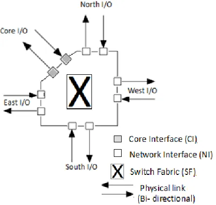
From the above discussions, NoC is a structure with collection of finite number of routers; each router has five input/output ports. Each router in a network structure is identified using its coordinate numbers or positions. Among five input/output ports, four input/output ports are dedicated to communicate with neighbour router, and remaining one is dedicated to communicate
with local or core elements. As shown in Figure. 2, the main elements of router are Switch Fabric (SF), Core Interface (CI), Network Interface (NI), Physical link (Bi-directional). The detailed explanations of each element are discussed below [9], [10].
Figure 2: 2-D Mesh Router Architecture
3.1.Physical Link
Physical link of router consists of bidirectional ports. The following sub-sections describe the explanations of input and output ports. Each input port has its own control and routing logic, buffer. In most of the router design, First in First out (FIFO) used as a buffer and FIFO is designing with shift register or dual line Static RAM. The size and depth of FIFO is fixed based on designers’ requirement. The position of FIFO fixes communication process, which is described in Figure. 3.
Figure 3: Status of FIFO buffer
[image:2.612.120.272.190.338.2]port. If there are more than one request from input ports to one output port, arbiter selects anyone of the requests based on highest priority, because arbiter uses rotating priority method. Among the five input/output ports, input port from east direction has highest priority. The main need of arbiter is, to improve the communication service via contention reduction [11], [12], [13].
3.2.Switch Fabric
[image:3.612.102.287.345.566.2]In router design, this switch fabric part have considered as important and central part. Switch fabric has two different kind of design method, one is Pass transistor based and another one is Multiplexer-based. According to input/output ports count of router, switch fabric will have cross point connections (Eg. For our design, switch fabric have 25 cross point connections because we have designed 5 input/output ports router). Figure 4 describes the architecture of switch fabric [14].
Figure 4: Switch Fabric using MUX
4. SWITCHING MECHANISMS
In network, each router communicates with neighbouring router, and it maintains forwarding an incoming packet until it reaches destination. Switching mechanisms have direct impact on network performance and buffer size through controlling packet forward process. Following sub-sections deal about different switching mechanisms.
4.1. Store and Forward
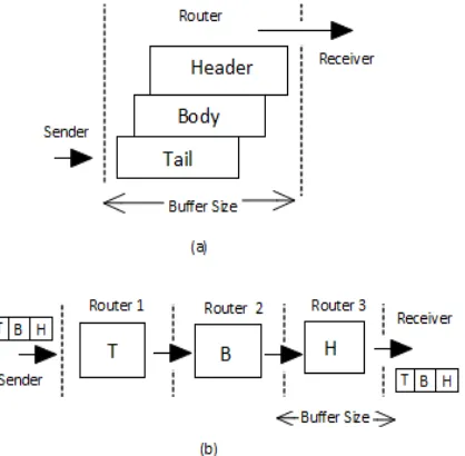
Data packet is split in to multiple flits as Header flit, Body flits and Tail flit. Each and every router receives header flit first, and then body flits. In order to avoid buffer overflow, keep the buffer size larger than total packet size. After receiving tail flit, router decides to send header flits of incoming data packet to neighbouring routers. The main advantage of this mechanism is simple control process and drawback is buffer size. Figure 5(a) describes the store and forward mechanism.
4.2.Wormhole
Wormhole mechanism is different from earlier method. In this mechanism, routers store only one flit and send the stored flit before arriving next flit to neighbouring routers as shown in Figure 5(b). Therefore, parts of a packet can be stored in multiple routers. The main advantage of this mechanism is, less buffer size but larger than header flit. But the main drawback of wormhole mechanism is blocking of continuous process due to contention of header flit.
Figure 5: (a) Store and Forward (b) Wormhole
4.3. Virtual Cut Through
[image:3.612.320.529.380.585.2]5. RELATED WORKS
For our study analysis, we chose Wormhole (WH) router due to its merits. The detailed working functionality of this router and proposed pipeline techniques will be given in the following sub sections.
5.1.Wormhole Router
Both the Circuit Switched (CS) and Virtual Through (VCT) routers use the concept of Cut-Through, which offer low latency network. The latency of these routers is independent of path length. VCT router requires extra buffer for blocked packets and CS router faces the problem of channel sharing. Therefore, Wormhole (WH) router introduced to overcome the above challenges without any compromise in latency.
Figure 6(a) shows the block diagram of WH router. The main blocks of WH router are Control Unit, Buffer, Switch Allocator and Switch Fabric. The primary functions of this router include flow control, routing, switching, multiplexing physical connections and clock recovery. Here, switch fabric is designed with the help of Multiplexer and Stop – Go mechanism used to manage buffers. And the depth of buffer is 8 bit. Figure 6 (b) shows the packet format, it consists of 32 – bit data, 3 – bit source and destination addresses and 1 – bit control [16].
Figure 6(a): Conventional Wormhole router
Figure 6(b): Packer format
5.2.Proposed Work
[image:4.612.312.522.295.431.2] [image:4.612.90.300.442.668.2]In order to improve the performance of WH router, here we introduced 5 – stage pipeline technique in this router and pipeline stages are Input Fetching, Path Allocation, Crossbar Stage, Switch Allocator Stage and last Destination Stage. Figure. 7 describes the each stages of pipeline. Horizontal position shows the number of clock cycles and vertical position shows the stages in the router.
Figure 7: Five stages of pipeline technique
The registers were added to store the data in the five stages such as IF, BS, SA, SWS and DS (i.e. Registers are added in the input channels, Path allocation stage, Switch Allocator, Cross bar and output stage). The proposed router takes 3 clock cycles to transfer the 1st data, but after 3 cycles the data will be received to the destination for each cycle. The speed of operation has been increased and reduces the critical path. But the area, power and latency has been increased slightly due to the additional registers.
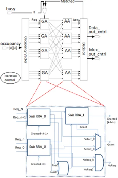
Generic RRA consists of two blocks, one is input selector and another one is pointer updater. Input selector selects one of the multiple requests from input ports and pointer updater generates a grant signal for next possible request. In Hierarchical RRA, first process is to divide number of inputs in to k subsets and which are called as Sub RRA (do the functions same as generic RRA), and they have local request. Local requests and grants are done in multiple stages of sub RRAs based on priority settings. A simple pass signal is used for smooth transitions between sub RRAs. These sub RRAs are arranged in two stages as hierarchically. First stage consists of sub_RRA_0s (select one request among multiple request signals to Hierarchical RRA based on priority, if no request, No request signal will be generated), second stage consists of sub_RRA_1s (generate grant signal for selected request signal by sub_RRA_0s, if no request, No request signal will be generated). Figure. 8 shows scheduler designed with Hierarchical RRA [17]. At last, we designed a novel router with 5 stage pipeline and hierarchical round robin arbiter to provide less area, less power and less slack time.
Figure 8: Scheduler with Hierarchical RRA
6. RESULTS AND DISCUSSIONS
Both routers WH and Wormhole with Pipeline (WHWP) were described using Verilog HDL. Modelsim XE is used for the functional and logic simulation. The Xilinx integrated tool environment ISE 09.2i is used for the automated logic synthesis, mapping, placing and routing of circuits. Tools included in this environment generate reports describing the area, power and delay of implementation, a netlist used for timing simulation, and a bitfile used to configure on targeted FPGA device.
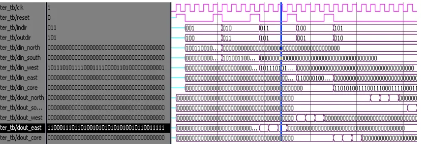
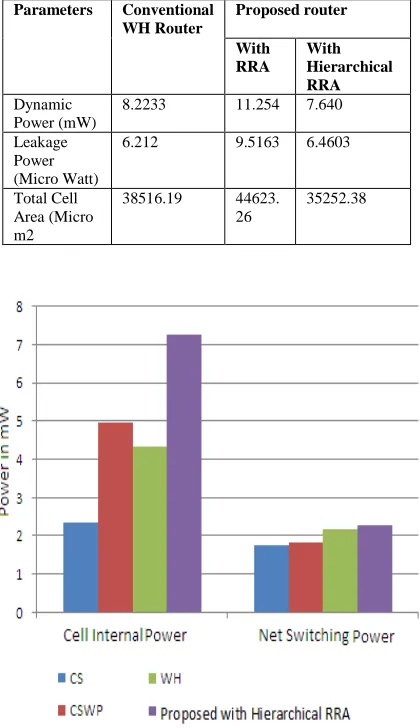
Simulated output of WH and WHWP routers are described in Figure. 8 (a) and (b). Verilog HDL code of WHWP router was synthesized and implemented in XILINX Virtex II Pro (selected device: 2v40cs144-6) FPGA Board. RTL schematic view of proposed router was achieved by synthesizing Veilog Code using Xilinx. Some hardware utilization feature parameters were measured and noted in Table 1. Other parameters like area, power and timing were calculated in 130 nm CMOS technology using Synopsys tool with nominal operating voltage of 1V and packet size is 39 bits. Library file used to calculate the area, power and slack time in Synopsys is fsc0h_d_sc_bc. By applying pipeline technique, slack time is reduced from 3.95 ns (data required time = 4.81, data arrival time = -0.86) to 2.04 ns (data required time = 3.83, data arrival time = -1.79). In order to verify the performance of this proposed architecture is then compared with Circuit Switch (CS) router and CS with Pipeline (CSWP) router. Figure 10 compares the cell internal and switching power of all the above four routers with packet size of 39 bits. Table 2 shows the comparison of area, power and slack time of CS, CSWP, WH and proposed routers. Similar with WH and proposed routers, CS and CSWP routers are described with Verilog HDL. Power, Slack and Area of CS and CSWP routers also calculated using Synopsys Design Compiler Tool with UMC 130nm Technology.
Figure 9(a): Simulation result of WH router
Figure 9(b): Simulation result of Proposed (with Hierarchical RRA) router
[image:6.612.91.517.74.250.2]By combining pipeline technique and hierarchical approach to generic RRA, conventional WH router achieved less slack time with less power and area consumption. Proposed router (with Hierarchical RRA) reduced 21.01% of total cell area of conventional WH router and 32.11% of total power consumption. The detailed comparison of conventional WH router, proposed (with RRA and Hierarchical RRA) router shows in Table 3.
Table 1: Comparison of synthesized parameters of Conventional WH router and proposed router with
Hierarchical RRA
Details Conventional
WH
Proposed (With Hierarchical
RRA)
Number of Ports 392 392
Number of Nets 435 633
Number of Cells 197 211
[image:6.612.102.516.283.425.2]Number of References 5 5
Table 2: Comparison of area, power and slack time of CS router and WH router with and proposed router with
RRA
[CB = Combinational Block, NCB = Non Combinational Block, DP = Dynamic Power, LP = Leakage Power, ST = Slack Time]
6.1.Impact of Flit Size
System designers have another degree of freedom to analyze the performance of NoC is represented by different flit Size with fixed payload size for each and every transmission. This
Parameters /Routers
CS CSWP WH Proposed
(With RRA)
CB Area (µm2)
4190 4040 8821 7450
NCB Area(µm2)
7989 15549 29695 37173
TC Area
(µm2) 12179 19589 38516 44623
DP (mW) 4.112 6.8256 8.2233 11.254 LP (µW) 2.7402 4.2768 6.2120 9.5163
[image:6.612.86.292.638.728.2]parameter is related to NoC bandwidth and it determines network buffering resources with respect to overall NoC power and area. Flit size can be customized and mainly affects the packetization logic at Network Interface block. Figure 11 and Figure 12 compare the impact of flit size on area and power consumption of WHWP router. When moving number of flits from 2 to 4, area penalty of combinational and non combinational blocks can be achieved but it reduces the dynamic power consumption. But leakage power slightly increased with decreases in flit size. Therefore we conclude this section, flit size and area of router are the trade-off.
Table 3: Comparison of area and power of conventional WH router and proposed routers (With RRA and
Hierarchical RRA)
Parameters Conventional WH Router
Proposed router
With RRA
With Hierarchical RRA
Dynamic Power (mW)
8.2233 11.254 7.640
Leakage Power (Micro Watt)
6.212 9.5163 6.4603
Total Cell Area (Micro m2
38516.19 44623. 26
35252.38
[image:7.612.91.301.309.673.2]Figure 10: Power consumption of CS, CSWP, WH and proposed with Hierarchical RRA
[image:7.612.322.514.344.485.2]Figure 11: Area of WHWP Router with different flit sizes.
Figure 12: Power consumption of WHWP with different flit size
7. CONCLUSIONS
ACKNOWLEDMENT
We would like to thank all the anonymous reviewers for their valuable suggestions. We also extend our sincere thanks to VLSI Design centre, Department of Electronics and Communication Engineering, PSG College of Technology, Coimbatore.
REFRENCES:
[1] International Technology Roadmap for Semiconductors [Online]. Available: http://public.itrs.net
[2] D. Sylvester and K. Keutzer, “A Global Wiring Paradigm for Deep Submicron Design,” IEEE
Trans. CAD/ICAS, Feb. 2000, pp. 242- 252.
[3] R. Ho, K. Mai, and M. Horowitz, “The Future of Wires,” Proc.the IEEE, Apr. 2001, pp. 490-504.
[4] L. Benini et al., “Networks on chips: A new SoC paradigm,” IEEE Computer vol. 36, no. 1, pp. 70–78, Jan. 2002.
[5] Ming Liu, “Improving the Performance of a Wormhole Router and Wormhole Flow Control”, MS Thesis, Sweden, 2005.
[6] A. Kumar, D. Manjunath, and J. Kuri,
“Communication Networking: An Analytical
Approach”, Morgan Kaufmann, 2004.
[7] P. T. Wolkotte, G. J. M. Smit, G. K. Rauwerda, and L. T. Smit, “An energy-efficient reconfigurable circuitswitched network-on-chip”, Proc. 19th IEEE International Conference on Parallel and Distributed
Processing Symposium, pp. 155-163, 2005.
[8] Felperin, S.A et. al, “Routing techniques for massively parallel communication”, Proc. Of IEEE, Vol. 79, pp. 488 – 503, 1991.
[9] D.C. Grunwald, D.A. Reed, “Networks for parallel processors: Measurements and prognostications”, Proceedings of the 3rd Conf. on Hypercube Concurrent Computer
Applications, New York, NY, pp. 610–619,
1998.
[10]L.M. Ni, P.K. McKinley, “A survey of wormhole routing techniques in direct networks”, IEEE Comput., 26 (2), pp. 62–76, 1993.
[11]K. M. Al-Tawil, M. Abd-El-Barr, and F. Ashraf, “A survey and comparison of wormhole routing techniques in mesh networks”, IEEE Network, vol. 11, pp. 38–45, 1997.
[12]Sorin Manolache, Petru Eles, Zebo Peng, “Buffer space optimisation with communication synthesis and traffic shaping for NoCs”, Proceedings of the conference on Design, automation and test in Europe:
Proceedings, March 06-10, 2006, Munich,
Germany.
[13]Michihiro Koibuchi, K.Anjo, Y. Yamada, A. Jouraku, H. Amano, "A Simple Data Transfer Technique Using Local Address for Networks-on-Chips," Parallel and Distributed
Systems, IEEE Transactions on, vol.17, no.12,
pp.1425-1437, Dec. 2006.
[14]Schroeder. M. D, Birrell. A.D, Burrows. M, Murray. H, Needham. R.M, Rodeheffer. T.L, Satterthwaite. E.H, Thacker, C.P, "Autonet: a high-speed, self-configuring local area network using point-to-point links," Selected
Areas in Communications, IEEE Journal on,
vol.9, no.8, pp.1318-1335, Oct 1991.
[15]Federico Angiolini , Paolo Meloni , Salvatore Carta , Luca Benini , Luigi Raffo, “Contrasting a NoC and a traditional interconnect fabric with layout awareness”, Proceedings of the conference on Design, automation and test in
Europe: Proceedings, Munich, Germany,
March 06-10, 2006.
[16]Federico Angiolini, Paolo Meloni, Luca Benini, Salvatore Carta, Luigi Raffo, “Networks on
Chips: A Synthesis Perspective”, ParCo 2005,
745-752.
[17]U. Saravanakumar, K.Rajasekar, R.
Rangarajan, “Implementation of scheduling algorithms for on chip communications”,