c:
RESEARCH
J
INC.
CRAY-1® AND CRAY X-MP
COMPUTER SYSTEMS
CAL ASSEMBLER VERSION 1
REFERENCE MANUAL
C::li=li.,o.,.,
-..."
RECORD OF REVISION RESEARCH. INC. PUBLICATION NUMBER SR-OOOO
Each time thi~ manual is revise~ and reprinted, all c.han~es is~ued against the p.revious version in the form of change packets are incorporated Into the new version and the new version IS assigned an alphabetic level. Between reprints, changes may be issued against the current version in the form of change packets. Each change packet is assigned a numeric designator, starting with 01 for the first change packet of each revision level.
Every page changed by a reprint or by a change packet has the revision level and change packet number in the lower righthand corner. Changes to part of a page are noted by a change bar along the margin of the page. A change bar in the margin opposite the page number indicates that the entire page is new; a dot in the same place indicates that information has been moved from one page to another, but has not otherwise changed.
Requests for copies of Cray Research, Inc. publications and comments about these publications should be directed to: CRAY RESEARCH, INC.,
1440 Northland Drive,
Mendota Heights, Minnesota 55120
Revision B C D D-Ol E F F-Ol Description
April 1975 - Original printing
June 1975 - This revision corrects various typographical and technical errors.
December 1975 - This revision corrects various typographical errors. Changes have been made to the block transfer
instructions. The title of this manual has been changed to the Preliminary CAL Assembler Reference Manual.
July 1976 - This manual describes CAL Version i, which executes on the CRAY-l. The manual replaces all previous versions of this publication. Since the manual has been completely rewritten, change bars are not used to indicate changes to the manual.
December 1976 - This revision provides much of the information relating to conditional pseudo instructions and macr%pdef operations that was missing from revision C.
June 1977 - Changes in this revision include the addition of the 042iOO instruction, START pseudo instruction, changes to the exchange package format, and additional minor technical changes.
August 1977 - This printing is a reprint of revision D with the D-Ol packet incorporated. There a~e no additional changes.
April 1978 - Changes in this revision include the addition of DFI and EFI instructions, the MICSIZE pseudo instruction, changes to the mode (M) register, the addition of DEBUG to the CAL control statement, provision for up to 10 system texts, and other minor technical changes.
Revision Description
F-02 October 1978 - This revision brings documentation in line with released version 1.03 of the CAL assembler.
G January 1979 - This revision is the same as Revision F with change packets F-Ol and F-02 incorporated.
G-Ol April 1979 - This change packet adds LIST options XNS, NXNX, WEM, and NWEMi describes the Vector Population Instructions
Option and the Monitor Mode Interrupt Option; describes the instructions associated with these options; and includes other technical changes that bring the document into agreement with version 1.06 of the CAL assembler.
G-02 July 1979 - This revision includes minor technical changes to bring the document into agreement with version 1.06 of the CAL assembler.
G-03 December 1979 - This revision includes minor technical changes to bring the document into agreement with version 1.07 of the CAL assembler.
G-04 April 1980 - This reV1S1on supports all models of the CRAY-l, including the CRAY-IA, CRAY-IB, and CRAY-l S Series Computer Systems.
H
H-01
I
1-01
The publication number has been changed from 2240000 to SR-OOOO.
April 1980 - This reprint is the same as Revision G with change packets G-Ol, G-02, G-03, and G-04 incorporated.
October 1980 - This change packet brings the manual into agreement with the released version 1.09. Major changes
include binary system text generation with the T parameter in the CAL control statement and new CAL messages.
February 1981 - This reprint is the same as Revision H with change packet H-Ol incorporated.
June 1981 - This change packet brings the manual into
1-02
J
J-Ol
April 19'82 - This change packet brings the manual into
agreement with version 1.11 of the assembler. Major changes include the following additions: the ALIGN pseudo instruction, the WRP, NWRP, WMR, and NWMR options to the CAL control
statement and the LIST pseudo instruction, the predefined micro SQUAL, two warning errors: Yl - EXTERNAL DECLARATION ERROR and Y2 - MACRO REDEFINED, and a logfile message. Miscellaneous technical and editorial changes are also
included.
February 1983 - This rewrite obsoletes all previous versions of the manual. The manual is reorganized; hardware
information has been deleted and can be found in the
appropriate Cray mainframe reference manual. Changes include adding CRAY X-MP symbolic machine instructions; the cpu=type
CAL control statement parameter; and the $CPU predefined
micro. This rewrite brings the manual into agreement with the released version 1.12 of the CAL Assembler.
July 1983 - This change packet brings the manual into
PREFACE
The CAL Assembler Version I allows the user to express symbolically all hardware functions of a mainframe for a Cray Research, Inc., CRAY-I or CRAY X-MP computer. This detailed and precise level of programming is of special aid in tailoring programs to the architecture of a Cray mainframe and writing programs requiring code that is optimized to the hardware.
Augmenting the instruction repertoire of CAL is a versatile set of pseudo instructions that provides the user with a variety of options for
generating macro instructions, controlling list output, organizing programs, etc.
Except where indicated the content of this manual applies to all series of Cray Research, Inc., computers. Detailed information concerning a
specific Cray mainframe is given in one of the following Cray mainframe reference manuals:
HR-0029 CRAY-l S Series Mainframe Reference Manual HR-0032 CRAY X-MP Series Mainframe Reference Manual HR-0064 CRAY-l M Series Mainframe Reference Manual
Detailed information about the Cray Operating System (COS) is presented in separate Cray Research, Inc., publications.
CONTENTS
PREFACE
1.
2.
INTRODUCTION •
EXECUTION OF THE CAL ASSEMBLER •
CRAY ASSEMBLY LANGUAGE SOURCE LINE FORMAT •
Continuation line Comment statement • STATEMENT FORMAT
Location field Result field Operand field Comment field CODING CONVENTIONS LINE EDITING
Concatenation • Micro substitution NAMES
REGISTER DESIGNATORS SYMBOLS
Symbol definition • Symbol attributes •
Word address, parcel address, or value Relocatable, external, or absolute Common •
Redefinable SYMBOL REFERENCE
Qualified symbols GLOBAL DEFINITIONS SPECIAL ELEMENTS DATA NOTATION
Numeric constants Character constants Data items
Literals
PREFIXED SYMBOLS, CONSTANTS, OR SPECIAL ELEMENTS •
P.
W.
Parcel-address prefix Word-address prefix
2. CRAY ASSEMBLY LANGUAGE (continued)
EXPRESSIONS • • • • • Adding operators
Multiplying operators • • Elements • • • • • Terms • • • • • •
Term attributes • • • • • • EXPRESSION EVALUATION • • • •
EXPRESSION ATTRIBUTES
Relocatable, external, or absolute
Parcel address, Word address, or value • • • • CHART METHOD OF EXPRESSION ATTRIBUTE EVALUATION
3. SYMBOLIC MACHINE INSTRUCTIONS
INSTRUCTION FORMAT • • • • • •
I-parcel instruction format with discrete j and k fields I-parcel instruction format with
combined j and k fields 2-parcel instruction format with
combined j, k, and m fields • • • • 2-parcel instruction format with
combined
i,
j, k, and m fields •SPECIAL REGISTER VALUES SYMBOLIC NOTATION
General requirements
Register designators • • Location field •
Result field • • • • Operand field
Special syntax forms
Register entry instructions • • • • • • • Entries into A registers •
Entries into S registers • • • Entries into V registers • Entries into Semaphore register Inter-register transfer instructions Transfers to A registers • • • • Transfers to S registers • • • • • • Transfers to intermediate registers Transfers to V registers • • • • • • Transfer to Vector Mask register • Transfer to Vector Length register Transfer to Semaphore register • Memory transfers • • • • • • • • • • Bidirectional memory transfers • Memory references • • • • Stores •
Loads • • • • • •
3. SYMBOLIC MACHINE INSTRUCTIONS (continued)
Integer arithmetic operations • • 24-bit integer arithmetic 64-bit integer arithmetic Floating-point arithmetic • • •
Normalized floating-point number Floating-point range errors
Floating-point addition and subtraction Floating-point multiplication
Reciprocal iteration • • • Reciprocal approximation • Logical operations • • • •
Logical products • • • Logical sums • • • • • Logical differences Logical equivalence Vector mask
Merge • • • • • • • Shift instructions
Bit count instructions • • • • Scalar population count
Vector population count • • • • Scalar population count parity • Vector population count parity • Scalar leading zero count
Branch instructions • • • • • • • • • Unconditional branch instructions Conditional branch instructions Return jump
Normal exit Error exit • Monitor instructions
Channel control
Set exchange address • Set real-time clock
Programmable clock interrupt instructions Interprocessor interrupt instructions Cluster number instructions • • • • • • • Operand range error interrupt instructions •
4. PSEUDO INSTRUCTIONS
INTRODUCTION • • • • • • • • RULES FOR PSEUDO INSTRUCTIONS INSTRUCTION DESCRIPTIONS •
Program control • • • • • •
IDENT - Identify program module • • • • END - End program module • • • •
ABS - Assemble absolute binary • •
4. PSEUDO INSTRUCTIONS (continued)
Loader linkage • • • • • • • • • • • • • • ENTRY - Specify entry symbols • • • •
EXT - Specify external symbols • • • • • • • • • • MODULE - Define program module type for loader •
START - Specify program entry • • • • Mode control • • • • • • • • • • • •
BASE - Declare base for numeric data QUAL - Qualify symbols • • • • • • • • • • Block control • • • • • • • •
Origin counter • • • • • Location counter • • • Word-bit-position counter
Force word boundary
Parcel-bit-position counter Force parcel boundary • • • • BLOCK - Local block assignment • COMMON - Common block assignment • ORG - Set *0 counter
BSS - Block save • • • LOC - Set * counter BITW - Set *W counter BITP - Set *P counter
ALIGN - Align on an instruction buffer boundary Error control • • • • • • • • • • • • • • • •
ERROR - Unconditional error generation • • ERRIF - Conditional error generation • Listing control • • • • • • • • • • • •
LIST - List control SPACE - List blank lines EJECT - Begin new page • •
TITLE - Specify listing title • • • • • • • • SUBTITLE - Specify listing subtitle • • • • TEXT - Declare beginning of global text source • ENDTEXT - Terminate global text source
Symbol definition • • •
= -
Equate symbol • • • • SET - Set symbol • • • • •MICSIZE - Set redefinable symbol to micro size • Data definition • • • • • • • • • •
CON - Generate constant
BSSZ - Generate zeroed block • DATA - Generate data words • • VWD - Variable word definition
REP - Loader replication directive • •
4. PSEUDO INSTRUCTIONS (continued)
5.
Conditional assembly • • • • • • • • • • • IFA - Test expression attribute for assembly
condition • • • • • • • • • • • • • • • • IFE - Test expressions for assembly condition IFC - Test character strings for assembly
condition • • • • • • • • • • • • SKIP - Unconditionally skip statements • • ENDIF - End conditional code sequence ELSE - Toggle assembly condition Examples of conditional assembly Instruction definition • • • • •
Definition header Definition body Definition end
Assembly source stack • • • • • • Formal parameters
MACRO - Macro definition Macro calls • • • • • •
OPDEF - Operation definition •
Symbolic instruction syntax • • • •
Expressions • • • •
Registers
Combinations • • • • Exceptions • • • • • LOCAL - Specify local symbols
ENDM - End macro or opdef definition • Opdef calls • • • • • • • • • • • • •
Examples of macro and opdef definitions and calls OPSYN - Synonymous operation • • • • • Code duplication • • • • • • • • • • • • • • • • • DUP - Duplicate code • • • • • • • • • • • • •
ECHO - Duplicate code with varying arguments • • • • • ENDDUP - End duplicated code • • •
STOPDUP - Stop duplication • • • Examples of duplicated sequences Micro definition • • • • • • •
Micro references • • • • • • • • •
MICRO - Micro def ini tion • • • • • • • • • OCTMIC and DECMIC - Octal and decimal micros • Predefined micros
CAL EXECUTION
CAL CONTROL STATEMENT SYSTEM TEXT
BINARY SYSTEM TEXT • •
APPENDIX SECTION
A.
B.
INSTRUCTION SUMMARIES
INSTRUCTION SUMMARY FOR CRAY-l COMPUTERS INSTRUCTION SUMMARY FOR CRAY X-MP COMPUTERS
PSEUDO INSTRUCTION INDEX •
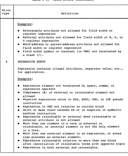
C. ASSEMBLY ERRORS
D. LOGFILE MESSAGES •
E. FORMAT OF ASSEMBLER LISTING
SOURCE STATEMENT LISTING CROSS REFERENCE LISTING
F. CHARACTER SET
G. CODING EXAMPLES
LONG VECTORS • • • LOOP COUNTER • •
ALTERNATE TESTS ON THE CONTENTS OF S REGISTERS CIRCULAR SHIFTS • • • •
H. CONDITIONS AND SPECIAL MACROS
CONDITIONS • •
Conditions on AO and SO • • Conditions on A and S registers Relational conditions •
Bit set conditions Compound conditions • SPECIAL MACROS •
$IF macro • •
$GOTO macro I. DATA GENERAL CAL • •
A-I A-I A-13 B-1 C-l D-l E-l E-l E-3 F-l G-l G-l G-2 G-2 G-3 B-1 B-1 B-1 B-1 B-2 B-2 B-3 B-3 B-3 B-5 I-I
SUMMARY OF DIFFERENCES BETWEEN CPU CAL AND DATA GENERAL CAL I-I
FIGURES
APPENDIX SECTION
A.
B.
INSTRUCTION SUMMARIES
INSTRUCTION SUMMARY FOR CRAY-l COMPUTERS INSTRUCTION SUMMARY FOR CRAY X-MP COMPUTERS
PSEUDO INSTRUCTION INDEX •
C. ASSEMBLY ERRORS
D. LOGFILE MESSAGES •
E. FORMAT OF ASSEMBLER LISTING SOURCE STATEMENT LISTING • CROSS REFERENCE LISTING
F. CHARACTER SET
G. CODING EXAMPLES
LONG VECTORS • • • LOOP COUNTER • •
ALTERNATE TESTS ON THE CONTENTS OF S REGISTERS • CIRCULAR SHIFTS • • • • •
H. STRUCTURED PROGRAMMING MACROS
I. DATA GENERAL CAL • • •
.
. .
A-I A-I A-13 B-1 C-l 0-1 E-l E-l E-3 F-l G-l G-l G-2 G-2 G-3 H-l I-ISUMMARY OF DIFFERENCES BETWEEN CPU CAL AND DATA GENERAL CAL I-I
FIGURES 3-1 3-2 3-3 3-4 3-5 3-6 3-7
General form for instructions • • • • • • • • • • • • • • I-parcel instruction format with discrete j and
k
fields • I-parcel instruction format with combined j and k fields • 2-parcel instruction format with combined j,k,
and m fields • • • • • • • • • • • • • • • •
2-parcel instruction format with combined
i,
j,k,
and m fields • • • • • • • • • • • • • Integer data formats • • • •
Floating-point data formats
TABLES
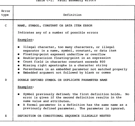
3-1 Instruction summary by functional unit C-l Fatal assembly errors
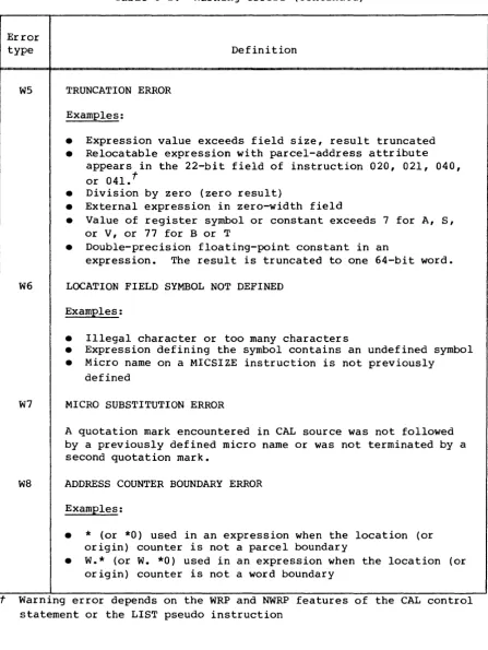
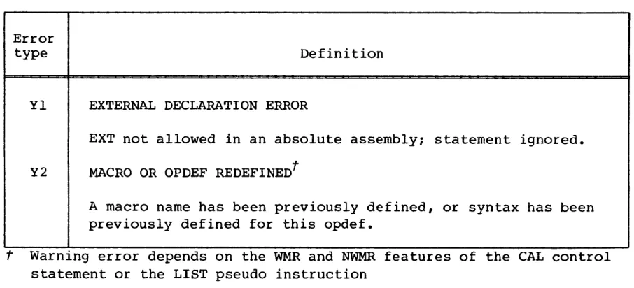
C-2 Warning assembly errors • • • • • • •
INDEX
INTRODUCTION
The Cray Research, Inc., Cray Assembly Language (CAL) provides the user with a powerful symbolic language for generation of object code to be loaded and executed on the mainframe of a CRAY-I or CRAY X-MP Computer System.
CAL source statements consist of symbolic machine instructions and pseudo instructions. The symbolic machine instructions provide a means of
expressing symbolically all functions of a Cray mainframe. Pseudo instructions allow programmer control of the assembly process.
Features inherent to CAL include:
• Free-field source statement format. Size and location of source statement fields are largely controlled by the user.
• Control of local and common blocks. The programmer can assign code or data segments to specific areas.
• Preloaded data. Data areas can be defined during assembly and loaded with the program.
• Data notation. Data can be designated in integer, floating-point, and character code notation.
• Word and parcel address arithmetic. Addresses can be specified as either word or parcel addresses.
• Binary control. The programmer can specify object code as either absolute or relocatable.
• Listing control. The programmer can control the content of the assembler listing.
• Micro coding. A character string can be defined in a program and substituted for each occurrence of its micro name in the program.
• Macro coding. Sequences of code are defined in a program or on a library, are substituted for each occurrence of the macro name in the program, and use parameters supplied with the macro call.
EXECUTION OF THE CAL ASSEMBLER
The CAL assembler executes under control of the Cray Operating System (COS). It has no hardware requirements beyond those required for the minimum system configuration.
The assembler is loaded and begins executing as a result of the CAL control statement called from a user job deck. Control statement parameters specify characteristics of an assembler run such as the dataset containing source statements and list output. See section 5 of this publication for a description of the CAL control statement.
The source statements can include more than one CAL program module. The assembler assembles each program module as it is encountered on the source dataset. Two passes are made by the assembler for each program module to be assembled. During the first pass, the assembler reads each source language statement instruction, expands sequences such as macro
instructions, generates the machine function codes, and assigns memory. During the second pass, the assembler assigns block origins, substitutes values for symbolic operands and addresses, and generates the object code and an associated listing.
eRA y ASSEMBLY LANGUAGE
2
This section presents the general rules and statement syntax for coding a Cray Assembly Language (CAL) program.
SOURCE LINE FORMAT
A CAL source statement consists of one to eight source lines. A source line is a maximum of 90 characters. The entire line is recorded in the list output dataset generated during a CAL assembly. The assembler interprets only the first 72 columns of a line. Remaining character positions may be ignored.
CONTINUATION LINE
A comma in column 1 indicates a continuation line. Columns 2 through 72 are then a continuation of the previous line. Up to seven continuation lines are allowed. Additional lines beyond seven are treated as comments.
COMMENT STATEMENT
An asterisk in column 1 indicates a comment statement. The assembler lists comment statements, but they have no effect on the program.
STATEMENT FORMAT
LOCATION FIELD
The location field begins in column 1 or 2 of a line and is terminated by a blank. The location field has no entry if columns 1 and 2 are blank. The content of the location field consists of a name, symbol, or error code and depends upon the requirements of the result field.
RESULT FIELD
The result field begins with the first nonblank character following the location field. It cannot begin before column 3 or after column 34. A
I
blank terminates the result field. The result field has no entry if onlyblank characters occur between the location field and column 35. A blank result field following a nonblank location field produces an informative error.
OPERAND FIELD
The operand field begins with the first nonblank character following a nonempty result field and is terminated by one or more blanks. If the result field terminates before column 33, the operand field must begin before column 35; otherwise, the field is considered empty. However, if the result field extends beyond column 32, the operand field must follow one blank separator and can begin after column 35.
COMMENT FIELD
The comment field is optional and begins with the first nonblank
character following the operand field or if the operand field is empty, does not begin before column 35. If the result field extends beyond column 32 and no operand entry is provided, two or more blanks must precede the comment field. The comment field can be the only field supplied in a statement.
CODING CONVENTIONS
Although CAL statements are essentially free field, adoption of a convention such as is suggested here provides more uniform and more
Beginning Column
1 1-8 9 10-18 19 20-33 34 35
LINE EDITING
Field
Blank, asterisk, or comma
Location field entry, left-justified Blank
Result field entry, left-justified Blank
Operand field entry, left-justified Blank
Beginning of comment field
CAL processes source statements sequentially from the source dataset. A macro or opdef definition is not immediately interpreted but is saved and
interpreted each time it is called. Before interpreting a statement, CAL performs two operations referred to as editing: concatenation and micro substitution.
CONCATENATION
CAL examines each line for the underscore (concatenation) character and deletes it so that the two adjoining columns are linked before the
statement is interpreted.
MICRO SUBSTITUTION
The CAL assembler searches for quotation marks (") which serve to delimit micro names. The first quotation mark indicates the beginning of a micro name; the second quotation mark identifies the end of a micro name.
Before a statement is interpreted, CAL replaces the micro name by the character string comprising the micro.
NAMES
A name is one to eight characters. The first character of a name must be alphabetic (A through Z), a dollar sign ($), a percent sign (%), or an at sign (@). Characters other than the first can also be decimal digits
Names are used to identify the following types of information:
• Program modules • Blocks
• Macro instructions • Micro character strings • Conditional sequences • Duplicated sequences
Unlike symbols, a name does not have a value or an attribute associated with it and cannot be used in expressions.
Different types of names do not conflict with each other or with
symbols. For example, a micro can have the same name as a macro and a program module can have the same name as a block.
REGISTER DESIGNATORS
A Cray computer system supports the following groups of operating registers:
• 8 address registers represented by An or A.x
• 64 intermediate address registers represented by Bn or B.x
• 8 shared intermediate address registers represented by SBn or
ss.x
t• 8 scalar registers represented by Sn or S.x
• 64 intermediate scalar registers represented by Tn or
T.x
• 8 shared intermediate scaler registers represented by STn or
ST.X
t
• 8 vector registers represented by Vn or V.x
• 32 semaphore registers represented by SMn or SM.xt
For the A, SB, S, ST, and V registers, n is a single digit in the range
o
through 7 and x is a symbol or a numeric constant. The value is truncated and an error is generated if x does not have a value in the range 0 through 7.For the Band T registers, 17, is one or two octal digits in the range
o
through 77 (octal) and x is a symbol or a numeric constant. Thevalue is truncated and an error is generated if x does not have a value in the range 0 through 77 (octal).
For the SM registers, 17, is one or two octal digits in the range 0 through 37 (octal) and x is a symbol or a numeric constant. The value
is truncated and an error is generated if x does not have a value in the range 0 through 37 (octal).
If
x
is a symbol, it can be used before it is defined but must be defined before program end. The symbol is evaluated during pass 2.For additional information on registers, see the appropriate Cray mainframe reference manual.
SYMBOLS
A symbol is one to eight characters that identifies a value and its associated attributes (see following description of symbol attributes) • The first character of a symbol must be alphabetic (A through Z), a
dollar sign ($), a percent sign (%), or an at sign (@). Characters other than the first can also be decimal digits (0 through 9).
A warning error is issued if a symbol is defined as one of the following register designators. CRAY X-MP specific registers get a warning error only when CAL is generating code for a CRAY X-MP mainframe (see
CPU=type option on the CAL control statement).
An, FAn
Bn, Bnn SBn
t
sn, FSn, PSn, ZSn, QSn Tn, Tnn
STnt
vn, FVn, pVn, Zvn, Qvn SMn;
t
SMnnt
t t RT, VM, CA, CL, CE, XA, VL, CI, SB, SM, MC
In the above, n is a single octal digit.
SYMBOL DEFINITION
The process of associating a symbol with a value and attributes is known as symbol definition. This association can occur in the following ways.
• A symbol used in the location field of a symbolic machine instruction or certain pseudo instructions is defined as an address having the current value of the location counter and having parcel-address or word-address attributes and relocatable or absolute attributes.
• A symbol used in the location field of a symbol-defining pseudo instruction is defined as having the value and attributes derived from an expression in the operand field of instruction. The type of symbol-defining pseudo instruction can cause the symbol to have a redefinable attribute. When a symbol is redefinable, a second attempt to define it must be through use of a redefinable pseudo
instruction causing the symbol to be assigned a new value and attributes.
• A symbol defined in a program module other than the module being currently assembled can be defined as having the attribute of external in the current program module. The true value of an external symbol is not known within the current program module.
SYMBOL ATTRIBUTES
Two or more attributes are assigned to a symbol when it is defined. These attributes are described in the following paragraphs.
Word address, parcel address, or value
Each symbol is assigned an attribute of word address, parcel address, or value. A symbol is assigned a word-address attribute if it appears in the location field of a pseudo instruction such as a BSS or BSSZ which defines words or if it is equated to an expression having a word-address attribute. A 22-bit value is associated with a word-address symbol.
A symbol is assigned a parcel-address attribute if it appears in the location field of a symbolic machine instruction or certain pseudo
Relocatable, external, or absolute
Each symbol is assigned the attribute of relocatable, external, or absolute.
A symbol is assigned an attribute of relocatable if it appears in a relocatable assembly in the location field of a machine instruction, BSS pseudo instruction, or data generation pseudo instruction such as BSSZ, CON, etc. A symbol is also relocatable if it is equated to an expression that is relocatable.
A symbol is assigned the attribute of external if it is defined by an EXT pseudo instruction. An external symbol defined in this manner has a value attribute and a value of O. A symbol is also assigned the attribute of external if it is equated to an expression that is
external. Such a symbol assumes the value of the expression and can have an attribute of parcel address, word address, or value.
If a symbol is neither relocatable nor external, it is assigned the attribute of absolute in a relocatable assembly. In an absolute
assembly, symbols that would be relocatable in a relocatable assembly are assigned the attribute of absolute. An exception occurs when the
absolute program module is divided into local blocks through use of BLOCK pseudo instructions. In this case, symbols defined in local blocks other
than the initial (nominal) block are assigned an attribute of relocatable during pass 1 and absolute during pass 2. The use of blocks is described
further under Block Control in section 4.
Common
A relocatable symbol is assigned an additional attribute of common if it is defined in a common block rather than a local block. Common blocks are allowed only in relocatable assemblies. The use of common blocks is described under Block Control in section 4.
Redefinable
SYMBOL REFERENCE
The occurrence of a symbol in a field other than the location field
constitutes a reference to the symbol and causes the value and attributes of the symbol to be used in place of the symbol.
A symbol reference can contain a prefix which causes the usual value and attributes associated with the symbol to be altered according to the prefix. The prefix affects only the specific reference with which it occurs. For details, refer to Prefixed Symbols or Constants later in this section.
QUALIFIED SYMBOLS
A symbol other than a global symbol can be rendered unique to a code sequence by specifying a symbol qualifier to be appended to all symbols defined within the sequence. The option to qualify symbols is initiated by one QUAL pseudo instruction and terminated by the next. If a symbol defined in the code sequence is referred to from within the sequence, it can be referred to without qualification. If, however, the symbol is referred to from outside of the code sequence in which it was defined, it must be referred to in the form
/quali[iep/symbol,
wherequali[iep
is a I-character to 8-character name and is defined through the use of a QUAL pseudo instruction.GLOBAL DEFINITIONS
Before the first IDENT pseudo instruction and between program modules (that is, between the END pseudo that terminates one program module and the IDENT that begins the next program module), CAL recognizes sequences of instructions that do not generate code but define symbols, macro and opdef instructions, and micros.
Definitions occurring before an IDENT pseudo instruction are conside~ed global and can be referred to without redefinition from within any of the program modules that occur subsequent to the definition. Micros,
redefinable symbols, and symbols of the form
%%xxxxxx,
wherex
is any nonblank character, represent an exception. While they can occur in such sequences, they are local to the program module that follows and are not known to the assembler after the next END pseudo instruction isSPECIAL ELEMENTS
The following designators can occur as elements of expressions and have special meaning to the assembler.
*
Denotes a value equal to the current location counter with parcel-address attribute and absolute or relocatable attribute, depending on type of assembly*0 Denotes a value equal to the current value of the origin counter with parcel-address attribute and absolute or relocatable
attribute
*w
*p
Denotes a value equal to the current value of the
word-bit-position counter with absolute and value attributes
Denotes a value equal to the current value of the
parcel-bit-position counter with absolute and value attributes
Expression elements are described later in this section. Counters are described under Block Control in section 4.
DATA NOTATION
In this publication, italicized lowercase letters, numbers, or symbols indicate variable information. Use of underlining in presenting
parameter options indicates default options. Use of parenthesis ( ) indicates optional information; use of brackets [ ] indicates required information.
Data can be in the form of numeric or character constants, data items, or literals. These forms are described and illustrated in the following paragraphs.
NUMERIC CONSTANTS
A numeric constant can be expressed in integer or floating-point notation. An integer constant has the following format:
A floating-point constant has the following format:
[integep. ]
(ppefix) [integep .fpaction] (decimal exponent) (binapy scale)
[ ·fpaction]
or
(ppefix) [integep] [decimal exponent] (binapy scale)
ppefix Numeric base used for the integep, fpaction, decimal exponent, and binapy scale. If no prefix is used, base is determined by the default mode of the assembler or by the BASE pseudo instruction. ppefix can be one of the following:
0' Octal (integer only) D' Decimal (default mode) X, Hexadecimal (integer only)
integep and/or fpaction
A non-empty string of digits as required by ppefix
deeimal exponent
Power of 10 by which the integep and/or fpaction is to be multiplied; indicates whether the constant is to be single precision (one 64-bit word) or double precision (two 64-bit words). n is an integer in the base specified by
ppefix. If no decimal exponent is provided, the constant occupies one word.
En or E+n Positive decimal exponent, single precision
E-n Negative decimal exponent, single precision
Dn or D+n Positive decimal exponent, double precision
D-n Negative decimal exponent, double precision
binapy scale
The integep and/or fpaction is to be multiplied by a power of 2. n is an integer in the base specified by ppefix.
sn
or S+n Positive binary exponentI
I
An integer constant is evaluated as a 64-bit twos-complement integer. Refer to figure 3-6 in section 3 for the twos-complement integer
formats. A floating-point constant is evaluated as a I-word or 2-word quantity, depending on the precision specified. See figure 3-7 in section 3 for the floating-point data formats.
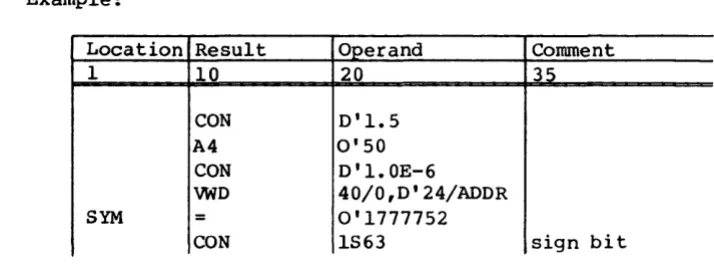
Example:
Location Result Operand Comment
I 10 20 35
CON 0'1.5
A4 0'50
CON D'I.OE-6
VWD 40/0,D' 24/ADDR
SYM = 0'1777752
CON lS63 sign bit
CHARACTER CONSTANTS
Character constants are expressed using the following format:
(prefix) ['character string'] (suffix)
prefix
Character set used for stored constant:A ASCII character set (default) C Control Data Display Code E EBCDIC character set
character string
sUffix
Appendix F lists the character set.
A string of zero or more characters from the ASCII character set. Two consecutive apostrophes (excluding the delimiting apostrophes) indicate a single apostrophe.
Justification and fill of character string:
H
L
R
Z
Left-justified, blank fill (default) Left-justified, zero fill
Right-justified, zero fill
[image:27.613.75.432.156.293.2]Example:
Location Result O~erand Comment
1 10 20 35
S3
'*
'RCON A'ABC'L
VWD 24/'OUT'
DATA ITEMS
A character or data item can be used in the operand field of the DATA, CON, and VWD pseudo instruction and in literals. The length of the data field occupied by a data item is determined by its type and size.
An integer data item has the following format:
(sign) (ppefix) [integep] (binapy scale)
A floating-point data item has the following format:
[integep. ]
(s ign) (ppefix) [integep .fpaction] (decimal exponent) (binapy scale) [ ·fpaction]
or
(sign) (ppefix) [integep] [decimal exponent] (binapy scale)
An integer data item occupies one 64-bit word. A floating-point data item occupies one word if single precision and two words if double precision.
A character string data item has the following format:
(ppefix) ['chapactep stping'] (count) (suffix)
In the above notation, descriptions given for numeric and character constants apply. The two added options, sign for numeric data items and count for character string data items, have the following
significance:
sign Data item is to be stored ones or twos complemented or uncomplemented
+ or omitted Uncomplemented
I
eount
Example:
Location 1
LITERALS
Length of the field in number of characters into which the data item is to be placed. count can only be used with a DATA pseudo instruction. If eount is not supplied, the
length is the number of words needed to hold the character string. If a count field is present, the length is the character count times the character width, so length is not necessarily an integral number of words. The character width is 8 bits for ASCII or EBCDIC, 6 bits for Control Data Display Code.
If an asterisk is in the count field, then the actual number of characters in the string is used as the count. The case where two apostrophes are used to represent a single apostrophe is counted as a single character.
If the base is M (mixed), CAL assumes that count is decimal. Refer to section 4 for a description of mixed base.
Result Operand Comment
~
10 20 35
DATA 'ERROR IN DSN'
DATA -D'1.5E2
DATA +0'20
WD 40/0,24/0'200
A literal is a read-only constant and has the following format when used as an element of an expression. data item represents any of the
formats for data items previously described.
=
[data item]The first use of a literal value in an expression causes the assembler to store the data item in one or more words in a special, local block known as the literals block. The value used in the expression in place of the literal data item is the address at which the literal is stored. A
subsequent reference to the literal value in an expression does not cause another store into the literals block~ the address of the previously
stored value is again used. This process avoids duplication of read-only data. A reference to a literal does not cause generation of new entries
I
Because the address of literal, rather than its value, is used in
evaluating expression elements, a literal has an attribute of relocatable in a relocatable assembly and during pass 1 of an absolute assembly. However, a literal has an attribute of absolute on pass 2 of an absolute assembly.
Examples of literals:
Location Result Operand Comment
1 10 20 35
A2 =0'101 Load address of word
containing 101
S3 ='A'
S4 =-2.1E2,0 Load -2.lE2 to S4
PREFIXED SYMBOLS, CONSTANTS, OR SPECIAL ELEMENTS
A symbol, constant, or special element can be prefixed by a P. or a
w.
causing the value to assume an attribute of parcel address or wordaddress, respectively, in the expression in which the reference appears.
A prefix does not permanently alter the attribute of a symbol; the effect of a prefix is for the current reference only.
P. - PARCEL-ADDRESS PREFIX
A symbol, special element, or constant can be prefixed by P. to specify the attribute of parcel address. If'a symbol,
sym,
has the attribute of word address, the value ofp.8ym
is the value ofsym
multiplied by four. A P. prefix to a symbol with value attribute or to a constant does not cause the value to be multiplied by four but it can be used to assign the parcel-address attribute.Example:
Location Result Operand Comment
1 10 20 35
ADDR CON P.ADDR
I
W. - WORD-ADDRESS PREFIX
A symbol, special element, or constant can be prefixed by W. to specify the attribute of word address. If a symbol,
sym,
has the attribute of parcel address, the value ofw.sym
is the value ofsym
divided by four. A W. prefix to a symbol with value-address attribute or to a constant does not cause the value to be divided by four but it can be used to assign the word-address attribute to the symbol or constant.Examples:
Location Result Operand Comment
1 10 20 35
AO W.ADDR
A4 W.BUFF+O'IOO
EXPRESSIONS
The result and operand fields for many source statements consist of entries known to CAL as expressions. An expression consists of one or more terms joined by special characters referred to as adding operators. A blank or a comma terminates an expression. A term consists of one or more elements joined by special characters referred to as multiplying operators. Thus, an expression can be diagrammed as follows:
Add Terml Add Term2-
.
-
Add TerInyz commaoPl oP2 °Pn or
(optional) blank
Any term in an expression can be diagrammed as follows:
Elementl Mult Element2
.
.
.
Mult ElementmoPl OP,n
I
ADDING OPERATORS
An adding operator joins two terms or precedes the first term of an expression. The two adding operators are:
+ Addition
Subtraction
MULTIPLYING OPERATORS
A multiplying operator joins two elements. Multiplying operators are:
*
Multiplication/ Division
ELEMENTS
An element is a symbol, constant, literal, or special element. It can also be one of these preceded by a complement (#) operator. However, an element preceded by # must be absolute. Examples of elements follow.
SIGMA
*
*w
Symbol
Special element Special element
0'77S3
A'ABC'R =A'ABC'
Numeric constant Character constant Literal
Attributes of elements are assigned by using the SET or
=
pseudoinstructions to define the attributes or by implication when the element is used.
TERMS
A term is an element or two or more elements joined by multiplying operators. Only one relocatable or external element can occur in a term. The following rules apply for terms.
• Two consecutive elements are illegal.
• The element to the right of / must be an absolute element; that is, it must be a constant or an absolute symbol or, in an absolute assembly, a literal or a special element as well as a constant or an absolute symbol.
• An element cannot be nUll; that is, two consecutive multiplying operators or a multiplying operator not followed by an element is
illegal.
• A term containing / must have an attribute of absolute up to the point at which the / is encountered (see the description of term attributes).
• Division by 0 produces an error.
TERM ATTRIBUTES
Attributes assigned to a term depend on the elements and operators comprising the term.
Every term is assigned an attribute of either external, absolute, or relocatable. A term assumes the attribute of external if it consists of a single external symbol. A term assumes the attribute of absolute if it contains only absolute elements. A term assumes an attribute of
relocatable if it contains one relocatable element and no external symbols.
Every term assumes an attribute of parcel address, word address, or value. The term attribute can vary as each element in the term is evaluated. The term's final attribute is the attribute in effect when the final (rightmost) element of the term is evaluated. As CAL
encounters each element in the left-to-right scan of a term, it assigns an attribute to the term based on the operator, if any, preceding the element, the attribute of any previous partial term, and the attribute of the element currently being evaluated.
In the following rules, consider that P, Wand V denote an element being incorporated into the term and having an attribute of parcel address, word address, or value, respectively. Consider, also, that ptepm, wtepm, and vtepm denote the attribute of the partial term resulting from all elements evaluated before the current element. The following rules can then be stated.
• Following evaluation of the element, a new partial term is
assigned a parcel-address attribute if the partial term, operator, and new element are one of the following combinations:
P
• Following evaluation of the element, a new partial term is
assigned a word-address attribute if the partial term, operator, and new element are one of the following combinations:
W
wteprrfkV wtepm/V vteffl£*W
• Following evaluation of the element, a new partial term is
assigned a value attribute if the partial term, operator, and new element are one of the following combinations:
V
v te prrfk
v
ptepm/p wtepm/W vtepmjV• In addition, any of the following combinations results in an attribute of value being assigned but is accompanied by a warning error.
ptepm*W wtep111*P ptepmjW wtepm/p vtepmjP vtepm/W pteprrfkP wtep111*W
EXPRESSION EVALUATION
Expressions are evaluated from left to right. Each term is evaluated from left to right, with CAL performing 64-bit integer multiplication or division as each multiplying operator is encountered. When a complete term has been evaluated, it is added or subtracted from the sum of the previous terms.
The assembler treats each element as 64-bit twos-complement integer. Sign extension is performed for elements with 22-bit (word-address) or
A relocatable term has a 64-bit integer coefficient associated with it, equal to the value of the term obtained when a one is substituted for the relocatable element. The value of a relocatable term is the value of the relocatable element multiplied by the coefficient.
The coefficient of each relocatable term is added to the coefficient or subtracted from the coefficient maintained for the corresponding
relocatable block represented in the expression.
EXPRESSION ATTRIBUTES
Expressions can be assigned the following attributes by the assembler.
• Relocatable, external, or absolute
• Parcel address, word address, or value
RELOCATABLE, EXTERNAL, or ABSOLUTE
An expression is relocatable if the coefficient for every block
represented in the expression is 0, except for one block which must have a coefficient of +1 (positive relocation). An expression error occurs if a coefficient does not equal 0 or +1, or if more than one coefficient is nonzero.
An expression is external if the expression contains one external term and if the coefficients of all relocatable blocks are O. An expression error occurs if more than one external term is present.
An expression is absolute if no external terms are present and the coefficients of all relocatable blocks are O.
PARCEL ADDRESS, WORD ADDRESS, OR VALUE
An expression has parcel-address attribute if at least one term has
parcel-address attribute and all other terms have value or parcel-address attributes.
An expression has word-address attribute if at least one term has word-address attribute and all other terms have value or word-address attributes.
I
An expression value is truncated to the field size of the expression destination. A warning error occurs if the leftmost bits lost in
truncation are not all zeros or all ones with the leftmost remaining bit also I (that is, a negative quantity).
A null (empty) expression is treated as an absolute value of O.
If an error other than a warning error occurs in evaluating an expression, the expression is treated as an absolute value of O.
Examples of expressions:
ALPHA An expression consisting of a single term
*W+BETA Two terms; *W and BETA.
GAMMA/4+DELTA*5 Two terms, each consisting of two elements
MU-NU*2+* Three terms; the first consisting only of MU, the second consisting of NU*2, and the third consisting only of the special element *.
0'100+=0'100 Two terms; a constant and the address of a literal.
In the following examples, Rand 5 are relocatable symbols in the same block, COM is relocatable in a common block, X and Yare external, and A
and B are absolute. The location counter is currently in the block containing Rand S.
The following expressions are relocatable:
*
W.*+B R+2 COM+R-S 3**-R-S =A'LITERAL' X+RR+S R/16*16
Rand S cancel
3** cancels -R and -5
Relocatable except in an absolute assembly, pass 2 Error; external and relocatable.
Error; relocation coefficient of 2.
Error; division of relocatable element is illegal.
The following expressions are external:
X+2 Y-IOO X+R-* X+2**-R-S -X+2
x+y
x/z
R, -* cancel relocation
Relocatable terms 2**, -R, -5 cancel each other Error; external cannot be negated.
Error; more than one external.
The following expressions are absolute:
A+B 'A'R-l 2*R-S-* 1/2*R A* (R-S)
Relocation of terms all cancel Equivalent to O*R
Error; parentheses not allowed
CHART METHOD OF EXPRESSION ATTRIBUTE EVALUATION
As shown in the following charts, if a symbol, literal, special element, or constant has the attribute of the left column (1st Term) and is added,
subtracted, multiplied, or divided by a symbol, literal, special element, or constant with the attribute of the top horizontal row (2nd Term), then the resulting attribute is determined at the intersection of the column and row by the arithmetic operator position (upper left corner of table).
:1;
V
P
W
1st Term
V
*
v v*
*
w wP
*3
p v*
v;lv;
v vW
W
w v 3v;lv
3
v v 3
~
v v2nd Term
V - Value P - Parcel W - Word
*
* /
v
P
W
1st Term
v
P*
v v?P
-;+;
:31 ;
*
*
x xX~IV~
x xW
*
x x 3X~IX;
x x**
x x2nd Term
v - Value P - Parcel W - Word
X - Error Message
3 - Warning Message
SYMBOLIC MACHINE INSTRUCTIONS
3
Each CRAY-l or CRAY X-MP mainframe machine instruction can be represented symbolically in Cray Assembly Language (CAL). The assembler identifies a symbolic instruction according to its syntax and generates a binary
machine instruction in the object code. An instruction is generated in the block in use when the instruction is interpreted.
INSTRUCTION FORMAT
Each instruction is either a I-parcel (l6-bit) instruction or a 2-parcel (32-bit) instruction. Instructions are packed four parcels per word. Parcels are numbered 0 through 3 from left to right and any parcel
position can be addressed in branch instructions. A 2-parcel instruction begins in any parcel of a word and can span a word boundary. For
example, a 2-parcel instruction beginning in the fourth parcel of a word ends in the first parcel of the next word. No padding to word boundaries is required. Figure 3-1 illustrates the general form of instructions.
First parcel Second parcel
g h i j k m
4 3 3 3 I 3 16 Bits
Figure 3-1. General form for instructions
Four variations of this general format use the fields differently; two forms are I-parcel formats and two are 2-parcel formats. The formats of these four variations are described below.
I-PARCEL INSTRUCTION FORMAT WITH DISCRETE j AND k FIELDS
The most common of the I-parcel instruction formats uses the
i,
j,and
k
fields as individual designators for operand and result registers (see figure 3-2). The g and h fields define the operation code. The [image:39.613.177.472.414.500.2]operand registers. Some instructions ignore one or more of the
i,
j, andk
fields. The following types of instructions use this format.• Arithmetic • Logical • Double shift
• Floating-point constant
g h i j k
4 131 3 3 I 3 Bits Operation Register
code designators
Figure 3-2. I-parcel instruction format with discrete j and k fields
I-PARCEL INSTRUCTION FORMAT WITH COMBINED j AND k FIELDS
Some I-parcel instructions use the j and k fields as a combined 6-bit field (see figure 3-3). The g and
h
fields contain the operation code, and the i field is generally a destination register identifier. The combined j and k fields generally contain a constant or a B or T register designator. The branch instruction 005 and the following types of instructions use the I-parcel instruction format with combined j andk fields.
• Constant
• Band T register block memory transfer • Band T register data transfer
• Single shift • Mask
g h i jk
4 3 3 6
I
Bits1
I
Operation code
Result Constant or register register
designator
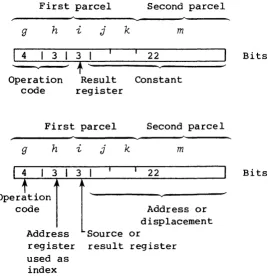
2-PARCEL INSTRUCTION FORMAT WITH COMBINED j,
k,
ANDm
FIELDSThe instruction type for a 22-bit immediate constant uses the combined
j,
k,
and m fields to hold the constant. The 7-bitgh
fieldcontains an operation code, and the 3-bit i field designates a result register. The instruction type using this format transfers the 22-bit
jkm constant to an A or S register.
The instruction type used for Ecalar memory transfers also requires a 22-bit jkm field for an address displacement. This instruction type uses the 4-bit g field for an operation code, the 3-bit h field to
designate an address index register, and the 3-bit i field to designate a source or result register. (See special register values.)
Figure 3-4 shows the two general applications for the 2-parcel instruction format with combined j,
k,
and m fields.First parcel
g h
i
j4 I 3 I 3
--...--
t
Operation Result code register
First parcel
g
Operation code
h i j k
k
Second parcel
m
22
Constant
Second parcel
m
22
Address or displacement Address Source or
register result register used as
index
Bits
Bits
Figure 3-4. 2-parcel instruction format
[image:41.613.171.444.281.558.2]NOTE
When using an immediate constant having a parcel value, and that is relocatable, the result of the relocation will be incorrect if the loader-determined actual address within the user's field length is greater than 1,048,575 because the resulting relocated value will have more than 22 significant bits.
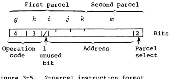
2-PARCEL INSTRUCTION FORMAT WITH COMBINED
i,
j, k, AND m FIELDSThe 2-parcel branch instruction type uses the combined
i,
j,k,
andm fields to contain a 24-bit address that allows branching to an instruction parcel (see figure 3-5). A 7-bit operation code (g~ is followed by an
ijkm
field. The high-order bit of thei
field is unused.First parcel Second parcel
g h i j k m
4 3
I~I
12I
Bits~
,
Operation 1 Address Parcel
code unused select
bit
Figure 3-5. 2-parcel instruction format
with combined
i,
j,k,
andm
fieldsSPECIAL REGISTER VALUES
[image:42.613.199.481.326.455.2]Field Operand value
Ah, hF=0 0
Ai, i=o
(AO)Aj, j=0 0
Ak, k=O 1
si, i;=o
(SO)Sj, j=O 0
Sk, 1<.=0 2**63
SYMBOLIC NOTATION
This section describes the notation used for coding symbolic machine instructions. Instructions are described in the following functional categories:
• Register entries
• Inter-register transfers • Memory transfers
• Integer arithmetic operations
• Floating-point arithmetic operations • Logical operations
• Bit counts
• Shift operations
• Program branches and exits • Monitor operations
Within each functional category, each instruction is presented,
explained, and followed by an example. Instructions are summarized by functional category below. Appendix A of this publication contains a cross reference to this section with the octal machine code as the
primary index. For descriptions of functional units, see the appropriate Cray mainframe reference manual.
GENERAL REQUIREMENTS
til ~ o o o o W I 0'\
LOGICAL OPERATIONS
S sj&sk vi sj&vk vi S Sj&SB
S SB&Sj
si IISk&sj si lISB&Sj
si sj!sk vi sj!Vk vi si Sj!SB
si SB!Sj
si sj\sk vi sj\vk vi
si Sj\SB si SB\Sj
si IISj\Sk si lISj\SB si iSB\Sj
VM vj,z VM Vj,N VM vj,P VM Vj,M si sj!Si&Sk
si sj! Si&SB vi sj!Vk&VM vi vi lIvM&vk
INTER-REGISTER TRANSFERS
Ai AI<. Si sk Ai -Ak si -sk
si !lSk Ai sj si Ak
si +Ak Ai VLt si +FAk
Ai Bjk si Tjk Ai SB/ si ST/
Ai CI si vj,Ak Ai CA,Aj si VM Ai CE,Aj si RT si SM t si sRjt
Ai si
Bjk Tjk
SBj Ait STj sit
vi vk vi -vk Vi,Ak VL Ak VM sj
VL 1 VM 0
SM sit sj
SYMBOLIC MACHINE INSTRUCTIONS
INTEGER ARITHMETIC OPERATIONS SHIFT INSTRUCTIONS RJ:;GISTER ENTRY INSTRUCTIONS
vj&vk Ai Aj+Ak SO Si<exp SO si>exp Ai exp si <exp
Ai Aj+l si si<exp si si>exp Ai -1 si lI>exp
Ai Aj-Ak si >exp
Ai Aj-l si Si,Sj<Ak si sj, Si>Ak si exp si II <exp
Ai Aj*Ak si Si,Sj<l si Sj,Si>l
si Si<Ak si Si>Ak si 0 si SB
si sj+sk vi sj+vk vi vj+vk si 1 si iSB
vj!Vk si sj-sk vi sj-vk vi vj-Vk vi vj<Ak vi vj>Ak si -1
vi vj<l vi Vj>l si 1- Vi,Ak 0 Si 2. vi 0 vi vj,vj<Ak vi vj,vj>Ak si 4.
vj\vk FLOATING-POINT OPERATIONS vi Vj,Vj<l vi Vj,Vj>l Si 0.4 sMjk 1 TSt si 0.6 sMjk Of
EFI sMjk It
DFl
si sj+Fsk vi sJ+Fvk vi vj+Fvk
PROGRAM BRANCHES AND EXITS
si +Fsk vi +Fvk BIT COUNT INSTRUCTIONS
J exp Ai psj vi pvj
si Sj-Fsk vi sj-FVk vi vj-Fvk
Bjk Ai Qsj vi Qvj
si -Fsk vi -Fvk J
Ai zsj JAZ exp JSZ exp
si sj*Fsk vi sj*Fvk vi vj*Fvk
vj:Vk&VM si sj*Hsk vi sj*Hvk vi vj*Hvk JAN exp JSN exp
JAP JSP
si sJo*Rsk vi sj*Rvk vi vj*Rvk exp exp
si sj*lsk vi sj*Ivk vi vj*Ivk JAM exp JSM exp MONITOR OPERATIONS
si /HSj vi /HVj
CA,Aj Ak CCI R exp
CL,Aj Ak ECl
EX ERR CI,Aj DCI
EX exptt ERR exptt MC,Ajt ERIt MEMORY TRANSFERS
XA Aj DRIt
DBMt RT sj CLN ot
EBMt PCl sj CLN It
IP It CLN 2t CMR t
IP ot CLN 3 t (store) (load)
,AO BJok,Ai Bjk,Ai ,AO O,AO Bjk,Ai Bjk,Ai O,AO
,AO Tjk,Ai Tjk,Ai ,AO REGISTER VALUE
O,AO Tjk,Ai Tjk,Ai O,AO LOGICAL OPERATORS
exp,Ah Ai Ai exp,Ah Ah, h=O 0 & 0101
exp,O Ai Ai exp,O llOO
exp, Ai Ai exp, Ai, i=O (AO) 0100
,M Ai Ai ,Ah
Aj, j=O 0 ! 0101
exp,Ah si si exp,Ah llOO
exp,O si si exp,o Ak, k=O 1 llOl
exp, si si exp,
\
,M si si ,Ah si, i=o (SO) 0101
ll££
,AO,Ak V;j vi ,AO,Ak sj, J=O 0 1001
,AO,l vj vi ,AO,l