COUPLING EFFECT OF UWB-EMP ON IRREGULAR
CAVITY
QIAN YANG,XIAOPENG YAN*, YONGLIANG LI,JIANTAO WANG,JING HAN
National Key Laboratory of Mechatronics Engineering and Control, Beijing Institute of Technology, Beijing, China
*Correspondence should be addressed to Xiaopeng Yan ([email protected])
ABSTRACT
The electromagnetic coupling effect on the irregular cavity which is acted by ultra wide band electromagnetic pulse (UWB-EMP) is studied. First, an irregular cavity structure model is established by using electromagnetic numerical calculation software (CST). Second, based on the model, the influences of UWB-EMP on the irregular cavity coupling efficiency are analyzed, when its rise time and pulse width change. Simulation show that: the shorter the rise time is, the better the coupling efficiency is gotten; pulse width almost has no influence on coupling efficiency. Furthermore, the signal frequency distribution of the typical positions in the cavity model are analyzed, which helps to improve the electronic equipment anti intense electromagnetic pulse interference abilities. The research results have an important guiding significance to improve the protection ability of the typical electronic equipment to UWB-EMP in practice.
Keywords: UWB-EMP, Coupling Effect, Irregular Cavity, Rise Time, Pulse Width
1. INTRODUCTION
The competition between the electronic
countermeasure (ECM) and electronic counter-countermeasure (ECCM) becomes increasingly in the future high-technology war. The research on how to strengthen the anti-electromagnetic interfere ability of the typical electronic devices has been paid more and more attention. As an important kind of electromagnetic pulse interference source, UWB-EMP features sharp rise edge, short pulse width, high peak power, and wide frequency band, which is harmful to electronic equipment[1-4]. At present, the researches of UWB-EMP influence on electronic equipment[5,6] mainly focus on the interference or damage of the semiconductor device in regular cavity, seldom concern the irregular cavity. Therefore, the study on electromagnetic energy coupled in irregular cavity has an important
engineering significance. By using the
electromagnetic numerical calculation software CST, a kind of irregular electronic equipment simulation model was established. As the rise time and pulse width of the UWB-EMP changes, the influences on the irregular cavity coupling efficiency, and the signal frequency distribution of the typical positions are analyzed. These results will provide reference for the electromagnetic protection technology.
2. SIMULATION MODEL
2.1CST Simulation Model
As a kind of electromagnetic numerical calculation software, CST has a formidable 3D modeling function, a new ideal boundary fitting. Compared with other traditional simulators, its magnitude is improved in precision. The transient solver can get electromagnetic characteristics of the simulation component in the whole frequency band by only one calculation, and the time domain waveforms can be offered obviously [7].
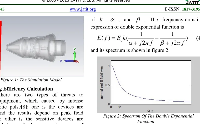
The CST calculation model of typical electronic equipment is built in fig.1. The external size is about 110mm×60mm×60mm, and the thickness of cavity is 2mm. A round through-hole is at the left side of the top and a rectangular hole on the lateral wall. The cavity is made by PEC, and interior is a vacuum space. Setting a rectangular coordinate, the
origin is at the center of the left top, and
z
axis iscoincided with the symmetry axis of the cavity. The
electromagnetic pulses propagate along -
z
Figure 1: The Simulation Model
2.2Coupling Efficiency Calculation
Mainly, there are two types of threats to electronic equipment, which caused by intense electromagnetic pulse[8]: one is the devices are interfered, and the results depend on peak field strength; the other is the sensitive devices are damaged, and the results depend on the energy of the field. The peak coupling efficiency and energy coupling efficiency are used to evaluate the coupling ability of electromagnetic pulse to the cavity in this paper.
The peak coupling efficiency is defined[9] as
20 lg
i po
E
CE
E
=
(1)where
E
i,E
o is the peak of electric field insideand outside the cavity respectively.
The energy coupling efficiency is defined as 2
2
( )
10 lg
10 lg
( )
i iW
o o
E t dt
W
CE
W
E t dt
=
=
∫
∫
(2)where
W
i,W
o stands for the energy inside andoutside the cavity respectively.
It is obvious that the higher the value of CE is, the stronger of coupling ability is, and vice versa.
3. SIMULATION AND DISCUSSION
The incident plane waves are UWB-EMP, and they are represented by a double exponential function. The time-domain expression of incident wave is
( )
(
t t)
p
E t
=
kE e
−α−
e
−β (3)where
E
p is the peak factor;k
is the normalizedcoefficient;
α
andβ
are the rising and fallingedge parameters of the pulse[10]. In simulation,
p
E
is set to 10kV/m, and the pulse rise time andpulse width can be changed by adjusting the value
of
k
,α
, andβ
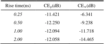
. The frequency-domainexpression of double exponential function is
0
1
1
( )
(
)
2
2
E f
E k
j
f
j
f
α
π
β
π
=
−
+
+
(4)and its spectrum is shown in figure 2.
Figure 2: Spectrum Of The Double Exponential Function
3.1The Influence of the Rise Time on Coupling Efficiency
Take a group of pulses with the same pulse widths and different rise time as the incident waves.
As shown in figure 3, the 10%Ep pulse width is
[image:2.612.321.524.393.502.2]0.5ns. The rise time is 20ps, 40ps, 73.4ps, and 100ps respectively.
Figure 3: Incident Waveforms At Different Rise Time
The time domain waves can be obtained by using the electric field probes, when the incident pulses coupling into the irregular cavity. Taking the electric signals at (0, 0, -40mm) in simulation model as an example, the time domain waveforms
[image:2.612.321.524.590.696.2]are shown in figure 4.
It can be inferred from figure 4. If the incident pulses width keeping the same and the rise time increasing the electric signals coupled into the cavity will be attenuated. That is because the slot in the cavity wall is equivalent to a high-pass filter,
which has a low-frequency cut off frequency
f
Lc.Only the components that are larger than
f
Lc in theincident pulse spectrum can couple into the cavity. The bandwidth BW[11] of the double exponential function is defined as
1
0.35
r
BW
t
=
(5)where
t
r is the pulse rise time. The BW will bereduced and the pulse energy will focus on the low
frequency part when the rise time
t
rof incidentpulse increases, which results in the reduction of the energy, coupled into the cavity and the electric field accordingly.
[image:3.612.321.523.192.324.2]The influence of the rise time on coupling efficiency can be obtained by equation (1) and (2). The peak coupling efficiency and the energy coupling efficiency at (0, 0, -40mm) in simulation model are shown in table1, when the rise times are 20ps, 40ps, 73.4ps, and 100ps respectively.
Table 1: The Influence Of The Rise Time On CE
Rise time(ps) CEp(dB) CEw(dB)
20 -10.889 -7.762
40 -12.250 -9.239
73.4 -16.029 -12.747
100 -18.215 -15.505
As shown in table 1: (1) both the peak coupling efficiency and the energy coupling efficiency reduce with the increase of the rise time, and then the energy coupled into the cavity reduces accordingly. Because the frequency distribution of double exponential pulse is determined by the rise time, the shorter rise time is, the greater bandwidth and the more high frequency component will be. Therefore, the energy coupled to the cavity increases and the coupling ability gets stronger. (2) by comparison, the peak coupling efficiency is always smaller than the energy coupling efficiency. That is because the energy coupled into the cavity appears oscillation which decreases slowly, leading
to the increase of integral to
E
i in equation (2).3.2 The Influence of the Pulse Width on Coupling Efficiency
Take a group of pulses with same rise time but different pulse width as the incident waves. As shown in figure 5, the rise time is 40ps and the
10%Ep pulse widths are 0.25ns, 0.5ns, 1ns, and 2ns
[image:3.612.321.523.370.477.2]respectively.
Figure 5: Incident Waveforms With Different Pulse Width
The time domain waveforms of the electric signals at (0, 0, -40mm) in simulation model are shown in figure 6.
Figure 6: Time Domain Waveforms At (0,0,-40mm)
As shown in figure 6, the coupled electric signals change a little, when the rise time of the incident pulse keep the same and the pulse widths increase. That is because the high frequency component of the pulses with same rise time and different pulse widths change very little, so the energy coupled into the cavity through the slot is almost the same.
The influence of the pulse width on the coupling efficiency can be obtained by equation (1) and (2). The peak coupling efficiency and the energy coupling efficiency at (0, 0, -40mm) in simulation model are shown in table 2, when the pulse widths are 0.25ns, 0.5ns, 1ns, and 2ns respectively.
Table 2: The Influence Of The Pulse Width On CE
Rise time(ns) CEp(dB) CEw(dB)
0.25 -11.421 -6.341
0.50 -12.250 -9.238
1.00 -12.094 -11.718
[image:3.612.106.281.444.517.2] [image:3.612.329.507.657.732.2]As shown in table2: The peak coupling efficiency changes very little but the energy coupling efficiency reduces, when the double exponential pulse rise time is invariable and the pulse width increases. Because the same pulse rise time the same high frequency component, and it has little influence on the peak coupling efficiency. But the
pulse width is closely related with the energy. The
wider the pulse width is, the greater the integral is
to
E
i in equation (2) in time domain, and the moreenergy is focused on the low frequency component in frequency domain. Therefore, the energy coupling efficiency reduces with the increase of the pulse width.
3.3 Signal Frequency Distribution at Typical Position
According to the resonant cavity theory, the external electromagnetic field coupled into the cavity through the slot can create a resonance frequency. If the resonance frequency is close to the operating frequency of the electronic equipment in the cavity, it will have an adverse impact on the normal performance of electronic equipment. The resonance frequency can be calculated by the internal dimension for the regular cavity [12]. But this theoretical calculation becomes difficult for irregular cavity due to complicated structures. In order to obtain the frequency distribution at typical position of irregular cavity, a FFT can be done on
the time domain signal by numerical simulation.
Taking incident wave with the rise time of 40ps and the 10%Ep pulse width of 0.5ns as an example, the signal frequency distributions at typical position can be analyzed.
(1) Vertical comparison
The electric signals at symmetry axis (0,0, -10mm), (0,0, -30mm), 40mm), and
(0,0,-80mm) are compared and the frequency
[image:4.612.322.525.227.349.2]distributions are shown in figure 7.
Figure 7: Spectrum Of Electric Signals At Symmetry Axis
As shown in figure 7, the frequency distributions at different positions are irregular, which is due to
the irregular vertical structure of the cavity of irregular cavity. At the same time, the main resonance frequencies are different, so are the numbers of the resonance frequencies.
(2) Horizontal comparison
The electric signals at (10mm,0,-40mm),
(-10mm,0,-40mm), (0,10mm,-40mm), and
[image:4.612.95.300.535.696.2](0,-10mm,-40mm) in z=-40mm cross section are compared and the frequency distributions are shown in figure 8.
Figure 8: Spectrum Of Electric Signals In Z=-40mm Cross Section
As shown in fig.8, the resonance frequencies at different positions are almost the same, because the horizontal structure of the cavity at z=-40mm is regular.
According to the above comparison, the inside structure of the cavity have a great influence on the resonance frequency distribution. For regular cavity, the resonance frequency distributions at different positions are almost the same. But for irregular cavity, the resonance frequency distributions are different. Although most electronic equipment cavities are irregular in actual project, the signal frequency distributions at typical
positions can be calculated by numerical
simulation.
4. CONCLUSION
positions of the irregular cavity are analyzed, which can provide the guidance for the operating frequency of the electronic equipment to avoid the resonance frequencies. The research results of this paper have an important significance on UWB-EMP protection for electronic equipment in practice.
ACKNOWLEDGEMENTS
This work was supported by the foundation of National Key Laboratory of Mechatronics Engineering and Control.
REFERENCES:
[1] W.D. Prather, C.E. Baum, J.M. Lehr, J.P. O'Loughlin, S. Tyo, J.S.H. Schoenberg, R.J. Torres, T.C. Tran, D.W. Scholfield, J. Gaudet, J.W. Burger, “Ultra-wideband source and
antenna research”, IEEE Transactions on
Plasma Science, Vol. 28, No. 5, 2000, pp. 1624-1630.
[2] Forrest J. Agee, John A. Gaudet, William D. Prather, “Focus on current topics in Air Force high-power microwave (HPM) research”, Proceedings SPIE 4371, Intense Microwave Pulses VIII, 1 (August 15, 2001).
[3] Forrest J. Agee, “Research issues and approaches in advanced high-power microwave sources”, Proceedings SPIE 3702, Intense Microwave Pulses VI, 2 (July 1, 1999)
[4] Bin Chen, Yongbin Wang, Juan Li, Jianzhong Wang, “ Electromagnetic pulse bombs' defense”, Proceedings SPIE 6795, Second International Conference on Space Information Technology 679554 (November 10, 2007).
[5] M. Camp, H. Garbe, D. Nitsch, “UWB and EMP susceptibility of modern electronics”, International Symposium on Electromagnetic Compatibility, IEEE Conference Publishing Services, August 13-17, 2001, pp. 1015-1020. [6] D. Nitsch, M. Camp, F. Sabath, J.L. ter Haseborg,
H. Garbe, “Susceptibility of some electronic
equipment to HPEM threats”, IEEE
Transactions on Electromagnetic Compatibility, Vol. 46, No. 3, 2004, pp. 380 – 389.
[7] Xinfeng Li, Guanghui Wei, Xiaodong Pan, “Research on transient electromagnetic
response of cable terminal”, Journal of
Ordnance Engineering College, Vol. 23, No. 3, 2011, pp. 101-111.
[8] Long Zhang, XiaoHui Wei, XiaoFeng Hu, “Influence of electromagnetic pulse parameters
on material shielding effectiveness”, Journal of
Microwaves, Vol. 28, No. 3, 2012, pp. 24-28.
[9] Bihua Zhou, Cheng Gao, Heming Ren, “The definition of EMP shielding effectiveness”, Asia-Pacific Conference on Environmental Electromagnetics, November 4-7, 2003, pp. 562-565.
[10] M. Camp, H. Garbe, “Parameter estimation of double exponential pulses (EMP, UWB) with least squares and Nelder Mead algorithm”,
IEEE Transactions on Electromagnetic
Compatibility, Vol. 46, No. 4, 2004, pp. 675-678.
[11] M. Shimanouchi, “New paradigm for signal paths in ATE pin electronics are needed for serialcom device testing”, IEEE International Test Conference, 2002, pp. 903-912.
[12] Shunkun Liu, Junmei Fu, Yusheng Chen, et al, “Numerical studies on resonant effects of
FREMP into a cavity through a slot”, High