Order No. AA-D599A-TC
DDCMP
DECNET
DIGITAL NETWORK ARCHITECTURE
Digital Data Communications
Message Protocol
D D C M P
Specification
Version 4.~
l-March-1978
DIGITAL EQUIPMENT CORPORATION
DDCMP Specification 4.0 March 1, 1978
Page 2
This material may be copied, in whole or in part, provided that the above copyright notice is included in each copy along with an acknowledgment that the copy describes the DDCMP protocol developed by Digital Equipment Corporation.
This material may be changed without notice by Digital Equipment Corporation, and Digital Equipment Corporation is not responsible for any errors which may appear herein.
DDCMP Specification 4.0 March 1, 1978
ABSTRACT
Page 3
The Digital Data Communications Message Protocol (DDCMP) provides a data link control procedure that ensures a reliable data communication path between communication devices connected by data links. DDCMP has been designed to operate over full- and half-duplex synchronous and asynchronous channels in both point-to-point and multipoint modes. It ,can be used in a variety of applications such as distributed computer
networks, host front-end processors, remote terminal concentrators, and remote job entry-exit systems.
DDCMP Specification 4.9 March 1, 1978
Table of Contents
Section
l.~ INTRODUCTION
2.0 FUNCTIONAL DESCRIPTION 2.1 Relationship to DECnet 2.2 Features
2.3 Operating Requirements 2.4 Data Link Functions 2.5 Functional Organization
3.~ INTERFACES 3.1 User Interface
3.2 Device Driver Interface
4.~ MESSAGE FORMATS 4.1 Notation
4.2 Data Messages 4.3 Control Messages 4.4 Maintenance Messages
5.0 OPERATION 5.1 Framing
5.2 Link Management 5.3 Message Exchange 5.4 Maintenance Mode
6.0 ERROR RECORDING 6.1 Threshold Counters 6.2 Cumulative counters 6.3 Background Counters
Page 4
6
7 7
8
9 11 12
17 17 19
22 22 23 25 30
31 31 37 43 58
DDCMP Specification 4.~ Page 5 March 1, 1978
APPENDIX A Glossary 63
APPENDIX B Formal Syntax Definition 65
APPENDIX C DDCMP Block Check Computation 68
APPENDIX D Format Summary 70
APPENDIX E Examples 71
APPENDIX F Revision History 78
List of Tables
Table No. Title Page
5-1 Summary of Synchronization Rules 36
5-2 Link Management Summary 41
5-3 Startup State Table 52
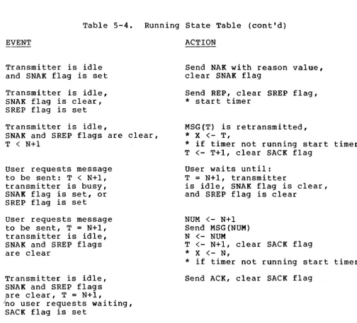
5-4 Running State Table 56
DDCMP Specification 4.0 INTRODUCTION
1.0 INTRODUCTION
Page 6
In the design of computer communications networks, one of the basic considerations is the physical transmission of data from one computer to another over a physical data channel. In the absence of transmission errors, this task becomes relatively simple. Once errors are introduced, however, data sequencing and synchronization problems occur between the transmitter and receiver. The solution to these problems consists of a data link control procedure or communications protocol that ensures the correct sequencing and integrity of data transmitted between computers over a data link.
DDCMP Specification 4.~
FUNCTIONAL DESCRIPTION
2.~ FUNCTIONAL DESCRIPTION
Page 7
The Digital Data Communications Message Protocol (DDCMP) has been designed for use over communication channels to provide data integrity, message sequencing, and management of the physical channel. The protocol defines the structure, content, and sequencing procedures for the transmission of data between computers and the techniques used for error detection and recovery. DDCMP resides at a level above the communication medium (i.e., the physical transmission of bits over the communication channel). DDCMP is concerned with the logical transmission of data grouped into physical blocks known as data messages. The primary function of the protocol is to exchang~ these data messages while ensuring their correct sequencing and integrity when sent over communication channels.
Computers adhering to the protocol will be able to correctly exchange data (between their respective address spaces) over a link. It is the level above the protocol that is concerned with the meaning and understanding of this data once correctly exchanged. with remote entry stations and concentrators, this includes device addressing, device control, and data formatting. with computer networks, it
includes problems of network routing, process synchronization, link multiplexing, flow control, and network management.
Programs wishing to communicate using DDCMP must agree on the syntax and semantics of the data transmitted within the DDCMP envelope. DDCMP may thus be viewed as a black box creating an error-free sequential communication path over which data may be transmitted. On multipoint links, DDCMP creates multiple sequential data paths between
the control station and the multiple tributaries on the link. If the physical channel connecting two computers is truly error-free, much of DDCMP is not necessary.
2.1 Relationship To DECnet
DECnet is a family of hardware and software products that create distributed networks from DIGITAL computers and their interconnecting data links. DECnet creates a general mechanism for sharing resources and providing interprogram communications within a distributed data processing environment. DECnet implementations adhere to a common network architecture that defines the structure and protocols each must use to communicate through the network. The DIGITAL Network Architecture (DNA) defines this common structure.
DNA provides a modular design for DECnet. Its functional components are defined within three distinct layers:
1. The Physical Link Control Layer (which provides the management of communications over a physical link).
2. The Network Services Layer source and destination
DDCMP Specification 4.9 FUNCTIONAL DESCRIPTION
channels) •
Page 8
3. The Application Layer (which supports user services and programs and provides I/O device and file access).
The DDCMP protocol creates and supports the functions of the Physical Link Control Layer within the DECnet Architecture. This layer provides control over the physical link operation and ensures both data integrity and the sequentiality of data transmitted over a single physical link. It should be noted that DECnet is not a part of the DDCMP standard specification and that DDCMP may be used, independently, in a wide variety of systems and environments where error-free communication is desired.
2.2 Features
DDCMP includes the following features:
1. Error detection using the l6-bit, CRC-l6, cyclic redundancy check error detection polynomial.
2. Error correction by retransmission.
3. Message sequencing, which permits up to 255 outstanding messages for pipelining.
4. Operation that (serial or (asynchronous wide variety interrupt and
is independent of the channel bit width parallel) and transmission characteristics and synchronous). DDCMP will operate with a
of communication hardware (e.g., character block transfer or DMA) and modems.
5. Common operation over full- and half-duplex, point-to-point and multipoint channels.
6. A positive startup procedure that synchronizes both ends of the link.
7. Simplicity and efficiency with only a few message formats.
8. A maintenance mode for diagnostic testing and bootstrapping functions.
DDCMP Specification 4.0
FUNCTIONAL DESCRIPTION Page 9
2.3 Operating Requirements
DDCMP was designed to serve the needs of interprocessor communications in a wide variety of applications and environments. DDCMP will provide:
1.
2.
3.
High Performance. links capable characteristics.
DDCMP will provide high data throughput on of such and make optimum use of link
Wide Applicability. DDCMP will ensure independent of channel type over a configurations.
operation that is wide range of system
Use of Available Hardware. with most communications minicomputers.
DDCMP will equipment
be that
able to operate is utilized with
2.3.1 Goals - In addition to ensuring the error-free transmission of data, DDCMP was designed to meet specific performance and compatibility requirements. These goals are:
1. Create a protocol for the transmission of data over communication . I inks to provide the correct sequencing and integrity of the data transmitted (even when the link may distort the information transmitted).
2. Operate over a wide variety of communications devices available on micro, mini, and maxi computers in bit serial
(asynchronous and synchronous) and bit-parallel modes.
3. Operate over point-to-point and multipoint circuits in both full- and half-duplex modes using a common set of messages and operating procedures.
4. Provide for the (transparent) data.
efficient transmission of binary
5. Ensure both high performance and simultaneous operation over full-duplex channels where long circuit delays may be encountered.
6. Provide error recording and reporting features so that a degraded link can be detected and repaired prior to link
failure.
7 • Provide a positive indication (and synchronization) that protocol module on the other end of the link
reinitialized or started.
DDCMP Specification 4.9 FUNCTIONAL DESCRIPTION
Page 10
8. Provide a basic operational mode for maintenance functions such as bootstrapping and diagnostic testing.
9. Provide a rigid enough protocol so that all implementations on the same channel type will operate together, independent of implementation techniques.
19. Create a protocol to minimize the memory requirements and execution time in the systems implementing the protocol.
11. Create a protocol that allows the physical characteristics of the channel to become transparent to the user.
2.3.2 Restrictions - Even though DDCMP is a general purpose link protocol offering high performance over a wide range of applications, there are a number of situations in which it may not be optimal. Some of these restrictions are:
1. DDCMP accepts data in blocks that are a multiple of 8-bit bytes. within a data block, a user can interpret the data in any manner (i.e., 5-bit quantities), but the total block must be a multiple of 8 bits.
2. DDCMP may not be optimal when operating on links with long propagation delays and a high probability of error. Optimal techniques in these cases might include forward error correction and single message retransmission. When an error occurs, nDCMP must go back to the last sequential correct message, thereby losing any pipelining in effect on the link.
3. DDCMP may not be suitable in some multipoint systems having many tributaries with low utilization and fast response requirements. Optimal techniques might include contention selection and broadcast. DDCMP uses a polling selection mechanism, which in some environments results in a longer response time.
4. On multipoint links, nDCMP supports only a single control station. No messages can be exchanged directly between tributaries. within a given system, the control station can not float among the tributaries.
DDCMP Specification 4.0 FUNCTIONAL DESCRIPTION
2.4 Data Link Functions
Page 11
The DDCMP protocol is an extension of the data communications link, providing a number of functions to the user of the protocol. DDCMP may be viewed as a black box creating an error-free sequential managed data link. On the transmit side, messages are given to DDCMP, which delivers them over the link and notifies the user when the delivery has successfully occurred. On the receive side, the user provides buffers that are filled with correctly received messages by DDCMP. The term "user" refers to the process or program exchanging messages with the protocol. In DECnet it might be the next higher level protocol (i.e., the Network Services Protocol). In other systems or structures it might be a service process or the end-user directly. DDCMP extends the capabilities of a data link to include the following features:
1. Creates an error-free data path. DDCMP transfers data between protocol users over a physical link, while maintaining data integrity within some very small undetected error probability. If data integrity cannot be maintained, no data will be transferred.
2. Transfers messages in proper sequence. Messages will be delivered from one user to the other in the same order as they are sent, even though DDCMP may require the use of retransmission or other error recovery techniques.
3. Manages the characteristics of the channel. If the channel requires receiver addressing and/or arbitration of transmission requests, ODCMP is responsible for that management.
4. Interface to modem control signals. DDCMP must interface with signals necessary for the operation of the physical channel, (e.g., modem control signals not handled by other components in the system). It may do this directly, leave it up to the hardware device driver, or let the user of the modem control code control these signals through the protocol
interface.
5. Accesses data in blocks consisting of byte quantities. DDCMP accepts data in blocks consisting of 8-bit bytes. All 256 8-bit combinations are transmittable, and transparent to DDCMP. The protocol will allow blocks of up to 16,383 bytes to be transmitted. However, the CRC-16 error detection polynomial used is most effective with blocks up to 4093 bytes long.
6. Provides restart or other end of the notify the user.
DDCMP Specification 4.0 FUNCTIONAL DESCRIPTION
Page 12
7. Provides start and stop control. The user controls the protocol and can start (or reinitialize), and stop (or halt) the operation of DDCMP.
8. Provides notification of channel error. When a persistent error is detected, the user is notified of such a condition. such errors might be (a) too high a bit error rate: (b) outages; (c) nonexistent communications: or (d) modem failure.
9. Provides a maintenance mode. nDCMP creates a data envelope with bit error-detection-only capability for use in diagnostic testing and system bootstrapping functions.
2.5 Functional Organization
From an operational viewpoint, nDCMP consists of three functional components: (1) Framing, (2) Link Management, and . (3) Message Exchange. The following sections provide a generic model describing each of these components. This model is helpful in understanding DnCMP operation. It is provided as an aid in implementation design (by enabling an individual to understand the protocol, its operationa]A intentions and motivations). It is not intended to describe specific operating details of DDCMP or subsets of DDCMP. For specific
information on the actual protocol operation refer to Section 5.0.
2.5.1 Framing Component - Framing is the process of locating the beginning and end of a message, at the receiving end o£ a link. Synchronization is the process of locating some entity (e.g., a bit o~
byte) and then staying in step or operating at the same rate as that entity. Synchronization of data on a link must occur at the bit, byte, and message levels before framing can be accomplished. The following paragraphs describe how nDCMP provides synchronization at these levels:
1. Bit synchronization. Locating a bit on the link. This function is accomplished by the modems or interfaces on the link and is not a part of DDCMP.
DDCMP Specification 4.~
FUNCTIONAL DESCRIPTION Page 13
row, and then counting every 8 bits as a byte. The unique pattern is such that any skewihg to the right or left will not produce a sequence match. On 8-bit or 8-bit multiple parallel links, byte synchronization is inherent in the link. For other types of links, techniques will have to be designed to locate the proper 8-bit byte window.
3. Message synchronization. Locating the first byte of a message. In DDCMP, this is done by searching for one of
three special starting bytes after achieving byte synchronization. Once one is found, simple rules will locate the end of the message. The message is framed and may be processed. The starting byte also defines the format type of the message and how the remaining bytes are to be interpreted.
The byte and message synchronization techniques were chosen to allow the greatest flexibility and independence from the actual data link characteristics. By using these techniques, DDCMP can operate on serial synchronous links with typical character interrupt or block transfer devices and on serial asynchronous links using 8-bit bytes. Byte synchronization is specified in DDCMP and is specific for each data link and its characteristics. Message synchronization is the same for all link types once byte synchronization has been established.
2.5.2 Link Management Component - The Link Management Component resolves the transmission and reception on links that are connected to two or more transmitters and/or receivers in a given direction. This is true of half-duplex and 'multipoint channels. Link management loccurs for both the transmitting and receiving functions.
On half-duplex links, one station must be receiving while the other is transmitting. The switching between transmit and receive is via a selection flag. The station that is transmitting ends transmission by setting the flag in its last message. This signals the receiver to complete reception of this message and then enter transmit mode.
For reception on multipoint links, the link appears as a party line. One station is designated the control station, the others are tributaries. All messages contain a tributary address to identify them. Messages to a tributary are received by all tributaries and ignored by all except the one with the matching address. Messages from tributaries are ignored by other tributaries and received by the control station that verifies the tributary address to be the one selected. Message traffic is only between the control station and tributaries.
DDCMP Specification 4.0 FUNCTIONAL DESCRIPTION
Page 14
to the control station in the last message of a transmission sequence.
Timers are used by half-duplex or control stations to handle the case of a lost flag (i.e., the message containing the flag is in error). A timer is started when waiting for the next message. If it expires it is assumed the selection flag was received in error and the station operates as if it received a valid selection flag.
2.5.3 Message Exchange Component - The message exchange component is the part of DDCMP that creates the sequential error-free link. This component transfers the data correctly and in sequence over a link that has some probability of introducing errors. Once framing is accomplished, this component operates at the message level, exchanging data and control messages. DDCMP is a positive acknowledgment retransmission protocol. For each data message correctly received and passed to the user, a positive acknowledgment is returned on the link notifying the transmitter of the correct receipt of the data message. If incorrectly received, the data message is not passed to the user and not acknowledged. Eventually, it will be retransmitted. DDCMP uses the CRC-16 cyclic redundancy check for error detection. This section describes the component parts of the message exchange mechanism along with their design characteristics and functions.
The basic positive acknowledgment message exchange component requires the following:
1. a data message with message number n;
2. a positive acknowledgment with message number n (ACK); and
3. a timer.
It operates in the following manner:
1. The transmitter puts the next message number n in the data message, adds the CRC block check to the message, puts it in the required framing envelope, and sends it. When i t has been transmitted on the link, a timer is started.
2. The receiver frames and receives the message, checks the CRC for errors, and compares the message number with the next expected. If the number is correct, the receiver returns a positive acknowledgment (ACK) with that number, passes the message to the receiving user, and increments the next expected number to n+l (modulo 256). If the number is in error, the message is ignored.
3. The transmitter follows one of two procedures;
a. It receives a positive acknowledgment number received with the one expected.
transmitter releases the message,
DDCMP Specification 4.0 FUNCTIONAL DESCRIPTION
Page 15
transmitting user of successful receipt, stops the timer, and increments the next message number to n+l (modulo 256). If the acknowledgment does not agree with the expected number it is ignored.
b. It receives nothing and the timer expires. The transmitter initiates error recovery. Various error recovery options are available. The ones used in DDCMP are presented below.
The timer in the message exchange component is keyed to the selection of a tributary (multipoint) or other station (half-duplex). That is, the controlling station must wait until a tributary or the other station is selected and transmits before it determines that a message or ACK was not properly received. This makes the timing independent of the selection of stations.
This mechanism is adequate for creating a message exchange component. The following additional messages and operational techniques of DDCMP are used to achieve higher performance (via pipelining) and faster error recovery (via error notification) but do not add to the basic integrity of the data transfer mechanisms.
1. Negative Acknowledgment (NAK). The time-out value (used to detect an error when an ACK is not returned) must be long enough to account for delays such as propagation, line turnaround, local processing of the data message, and the generation of the ACK. Time-out values might be a few seconds while the actual delay may be on the order of a few milliseconds. If the only way to determine an error is to wait for a time-out, undue waste and inefficiency are encountered. A negative acknowledgment provides a means for more immediate notification of some error conditions. If the receiver does not receive the message correctly, it sends a NAK, which triggers the retransmission long before the timer expires.
In DDCMP, NAKs are sent in response to cyclic redundancy check errors, but not to wrong message numbers. If the receiver gets a message with the wrong number, the message is ignored and the time-out condition triggers the transmitter to retransmit. If NAKs were sent in both cases, long delays could occur under certain timing conditions.
DDCMP Specification 4.0 FUNCTIONAL DESCRIPTION
Page 16
is restarted after sending a REP. If it expires again the process is repeated. After some specified number of these time-outs, the transmitter will notify the DDCMP user, who may declare the link out-of-service.
3. pipelining. The ability to send more than one message without waiting for ACKs to each successive message is called pipelining. within DDCMP, messages are numbered from 0 to 255. This numbering is cyclic (modulo 256) in that after message number 255 the next message number is 0. ACKs not only confirm that the specified message number has been received correctly, but that all previous messages with numbers between the one acknowledged in the last ACK and the one acknowledged by the current ACK (modulo 256) have been received correctly. If an ACK message is in error, the information lost is automatically included in subsequent ACKs, eliminating the sending of REP messages if the ACKs are received prior to the expiration of the transmission timer. This technique is also used with the REP message, the number sent in the REP being the number of the last message transmitted.
4. Piggybacking. The purpose of an ACK is to convey the message number of the last successfully received data message. If data message traffic is going in both directions, the ACK number can be sent piggybacked on or within the frame of the message going in the other direction. This technique saves separate framing overhead for the ACK.
5. ACK implied in NAK. The number referenced in a NAK reply identifies the last successfully received message as well as noting a received error. So NAK implies that all messages prior to the one being negatively acknowledged were received correctly.
DDCMP Specification
4.e
INTERFACES3.e
INTERFACESPage 17
This section describes how ODCMP is viewed by a user of the protocol and how the physical interface device or driver is viewed by DDCMP. A generic description of the information that must be passed across the interfaces to the user and the device is presented as an aid for implementation design.
3.1 User Interface
The interface between nDCMP and the user consists of a number of commands to DDCMP and responses from DDCMP. In these commands and responses, the user exchanges data and control information with the
~rotocol. The actual interface mechanism depends heavily on the
ffeatures and capabilities within the operating systems running DDCMP. Mechanisms for exchanging this information might include shared tables, calls with parameter lists, I/O registers, and interrupt mechanisms.
Three kinds of information are exchanged in the command/response sequences: (1) data, (2) control information, and (3) error information. Data is the user information to be sent or received by ithe protocol. Its description usually consists of a starting buffer 'address and a length or character count, or a chain of addresses and counts. Control is information to start and stop the protocol and notify the user of protocol initialization. Error information is provided by the protocol for use in determining the physical condition of the link and when maintenance is necessary. DDCMP is totally controlled by the user of the protocol. It is only activated by a command request from the user and continues to operate even when large numbers of data errors occur on the physical link. It is started, gtopped, and reinitialized only upon commands from the user. On
~ultipoint links, independent command and response sequences are maintained between the control station and each tributary on the link. The link appears as multiple point-to-point links, one for each tributary address.
OOCMP Specification
4.e
INTERFACES3.1.1 Commands To ODCMP - The basic commands to DDCMP are:
Page 18
1. Initialize Link. Initialize the protocol and start the data link.
2. Stop Link. Halt the protocol. In some dial-up situations, a method may be employed to force the modem to hang-up.
3. Transmit Message. Give a message to ODCMP for transmission. As an option the user may specify that it wishes to send the message within the maintenance mode, or the protocol implementation may require a separate Maintenance Mode Initialization command prior to a transmit request.
4. Receive Message. Give an empty buffer to DDCMP for receptior~ of the next sequential message. Alternatively, the user might supply a pool of buffers to DDCMP initially, and have the protocol select one. In this mode, there will be a command to return empty buffers to the pool so they may again be used by DDCMP.
5. Return Transmit Buffers. This optional command, which can be employed after halting DDCMP, returns outstanding transmit buffers to the user. The response to this command woul~ include whether they were already transmitted and acknowledged, not yet acknowledged, or not yet transmitted.
6. Enter Maintenance Mode. This command is an option to first change to the maintenance mode before transmitting or receiving maintenace mode messages.
3.1.2 Responses From ODCMP - The responses from ODCMP are:
1. Initialization on Other End. The other end has restarted or initialized. This response will halt the protocol. The command to restart the protocol on this end will be an
Initialize Link command.
2. Initialization Complete. Response to Initialize Link command. This response is optional. If i t is omitted, the reply to a successfully received or transmitted message will serve as initialization completion notification.
3. Message Transmitted. Response to the Transmit Message command. The message was successfully received on the other end (acknowledged).
DDCMP Specification 4.0 INTERFACES
Page 19
Optionally, if the message was received in the maintenance mode it may be so marked, or a separate response may be first sent to the user to indicate that the other end is in maintenance mode. At that point, the protocol will halt, and the user will have to initialize the protocol into the maintenance mode before receiving maintenance mode messages.
5. Transient Error Threshold Counter Overflow. An error threshold counter has overflowed. The protocol will continue operation. It must be halted by the user if the user wishes to cease operation (refer to Section 6.0, Error Recording).
6. Persistent Error. An error has occurred from which recovery may not be possible. Some implementations of the protocol may halt operation. Some errors that are classified as persistent errors in one system, might be transient errors in another. The various types of errors are discussed in Section 6.0.
3.2 Device Driver Interface
The interface between DDCMP and the line driver includes a number of commands and responses used to transmit and receive message blocks to and from the link, respectively. The actual interface depends heavily on the mechanisms and capabilities available in the I/O structure of the system within which this interface operates. It also depends heavily on the split of protocol functions between DDCMP and the driver. The driver may be very protocol independent and rely on heavy interaction with DDCMP for message framing, CRC calculation, and the syntactic and semantic interpretation of message fields. Alternately, it may embody much of DDCMP including framing, CRC checking, link management, and link turnaround. In this mode, there would be less interaction with the semantic or message exchange portion of DDCMP. Consequently the driver would handle many of the functions related to link type and device characteristics. The choice of driver capabilities and the split of functions depends on system characteristics, device requirements, driver generality, and the interface to other protocols. The interface described here lies between these two extremes and is presented as an aid to understanding what information must pass across this interface.
DDCMP Specification 4.~
INTERFACES
Page 20
3.2.1 Commands To The Driver - The driver receives the commands:
following
1. Link and Modem Control. These commands activate and connect a physical link to DDCMP. They also control the modem signals necessary for proper operation. These signals may be implicit in enabling the link (i.e., turn Data Terminal Ready (DTR) on) or explicit via modem control commands to allow DDCMP to directly control the modem. Typical commands might be:
a. Enable link. This command connects the driver to DDCMP and turns DTR on.
b. Disable link. This command disconnects the driver from DDCMP and turns DTR off.
2. Buffer Management. Received message blocks are passed to DDCMP via buffers. The buffers may be (a) individually given to the driver via Receive commands or (b) initially allocated to the driver in a Set buffers command or the Enable link command. In this second mode there must also be a command for DDCMP to return the buffers to the driver. On disconnection (Disable link command), the buffers must be returned to DDCMP or a buffer pool.
3. Transmit a Block. This command passes a block to the driver for transmission. The request might include one of the following options: (a) proceed with a synchronization sequence; (b) end with a pad; (c) calculate CRC: or (d) shutdown the transmitter after the message. These options depend on the precise division of functions between the driver and protocol.
4. Receive a Block. This command passes buffers to the driver if individual explicit buffers are used. Otherwise, the driver might simply queue received blocks to DDCMP using buffers from a previously obtained pool (as noted in 2). This command may also request the driver to resynchronize or reframe the receiver or there may be a separate Resync Receiver command.
DDCMP Specification 4.~
INTERFACES Page 21
3.2.2 Responses From The Driver - The driver issues the following responses:
1. Modem Status. The driver returns modem signals, such as Data Set Ready (DSR), if appropriate to the interface.
2. Received Block. The driver passes a received data block to DDCMP. Depending on the functional split between the driver and DDCMP, the driver may calculate CRC (either in the driver or device itself) and pass this status with the block. When DDCMP is finished with the buffer it returns it to the driver via either (a) a Receive command or (b) a Return Buffer command, depending on the buffering scheme used.
DDCMP Specification 4.0 MESSAGE FORMATS
4.0 MESSAGE FORMATS
Page 22
This section describes the message formats of DDCMP. Data is exchanged over DDCMP links between the data source (master) and data sink (slave) within numbered data messages. Responses and control information are returned from the slave to the master within unnumbered control messages. Stations contain both a master and slave. For the purpose of exchanging data, the station plays the role of master or slave depending on whether i t is transmitting or receiving the data. It is a distinction used for easy understanding and explanation of DDCMP. In reality, data is usually exchanged in both directions. In the following explanation only a single direction
is described.
Each data message carries a number assuring correct message sequencin~ at the slave. The numbering begins with number one after initialization via the STRT/STACK control message sequence and is incremented by one (modulo 256) for each subsequent data message. The slave always acknowledges the correct receipt of data messages by returning the message number as a response either in the response field of numbered data messages going in the reverse direction, or, in an ACK unnumbered control message. For efficiency, an acknowledgment of the data message with number n implies an acknowledgment of all data messages sent up to and including data message number n.A
Retransmission is used to recover from errors. The error recovery mechanism uses timeouts and NAK and REP control messages to resynchronize and cause retransmission if required. All messages also include station addresses and link control flags for use on multipoint and half-duplex channels.
4.1 Notation
The following notation is used to describe the messages:
Field (length) : coding = description of field Field = the name of the field being described
length = the length of the field as:
(1) a number meaning the number of 8-bit bytes or
(2) a number followed by a B meaning the number of bits
coding
=
the representation type used: BBM C Null
= Binary
= bit map (each bit has independent meaning)
= constant
= interpretation data dependent
DDCMP Specification 4.0
MESSAGE FORMATS Page 23
All numeric values in this document representation unless otherwise noted.
are shown in decimal
All header fields and bytes of data least-significant bit first on the specified.
are transmitted low-order or data links unless otherwise
4.2 Data Messages
Numbered data messages carry user data over DDCMP links. of a numbered message is:
The format
+---+---+---+----+---+----+---+----+---+
!SOH!COUNT!FLAGS!RESP!NUM!ADDR!BLKCKl!DATA!BLKCK2!
+---+---+---+----+---+----+---+----+---+
where:
SOH (1) C
=
COUNT (14B) B =
FLAGS (2B) BM =
the numbered data message identifier. value of 129 (octal - 201).
It has a
the byte count field. It specifies the number of 8-bit bytes in the DATA field. The value zero is not allowed.
the link flags. ownership and
flags are:
They are message
used to control synchronization.
link These
bit 0 = quick sync flag (QSYNC flag), used to notify the receiver that the next message will not abut this message and resynchronization should follow this message. The quick sync flag reduces the length of sync sequences on synchronous links.
bit 1 = select flag (SELECT flag), used to control transmission ownership on multipoint and half-duplex links. Reverses link direction on half-duplex links. Invites a
DDCMP Specification 4.0 MESSAGE FORMATS
Page 24
RESP{l) B
=
NUM (1) : B =
ADDR{l) B =
BLKCKl(2) B =
DATA (COUNT) =
BLKCK2(2) B =
NOTE
COUNT and FLAGS form a 2-byte quantity. The first byte contains the 8 low-order bits of the COUNT. The second byte contains the 6 high-order bits of the COUNT, the SELECT flag the highest order or most significant bit of the byte, and the QSYNC
flag the next bit in the byte.
! S ! Q ! COUNT !
high order bit transmitted last
low order bit transmitted first
the response number. It is used to acknowledge correctly received messages (the piggybacked ACK).
It is the number of the last consecutive correctly received message received from the addressed station by the station transmitting this message. It implies that all unacknowledged messages between the one acknowledged in the last RESP field received and the one acknowledged by this RESP field (modulo 256), have been received correctly.
the transmit number. It is used to denote the number of this data message.
the station address field. It is used to designate the address of tributary stations on multipoint links. Stations on point-to-point links use the address value 1.
the block check on the numbered message header. It is computed on SOH through AD DR using the CRC-16 polynomial (XA
16+XA
15+XA
2+1). BLKCKI is initialized to zero prior to computation and transmitted XA
15 bit first. On reception the inclusion of BLKCKI in the computation will result in a zero remainder or CRC if no errors exist. See Appendix C for a description of CRC computation.
the numbered message data field. This field is totally transparent to the protocol and has no restrictions on bit patterns, groupings, or interpretations. The only requirement is that it contain the number of 8-bit bytes specified in the COUNT field.
the block check on the data field. It is computed on the DATA field only using the polynomial and
OOCMP Specification 4.0 MESSAGE'FORMATS
Page 25
4.3 Control Messages
Unnumbered control messages carry channel control information, transmission status, and initialization notification between the protocol modules themselves. The individual fields are specific for each type of control message. Control messages have the following general form:
+---+----+---+---+----+----+----+---+ ! ENQ!TYPE! SUBTYPE! FLAGS! RCVR! SNDR!ADDR!BLKCK3! +---+----+---+---+----+----+----+---+
where:
j ENQ (l) C =
TYPE (l) : B =
SUBTYPE (6B) B =
FLAGS (2B) BM
=
RCVR(l) B =
SNOR(l) B
=
AOOR{l) B =
BLKCK3(2) B =
the unnumbered control message identifier. It has a value of 5 (octal - 005).
the control message type. This value denotes each control message.
the subtype or type modifier field. It provides additional information for some message types. Its use is specific for each message type.
the link flags. They are the same as described for numbered data messages (See Section 4.2).
the control message receiver field. It is used to pass information from the data message receiver or slave station to tpe data message sender or master station. Its use is specific for each control message type.
the control message sender field. It is used to pass information from the data message sender or master to the data message receiver or slave. Its use is specific for each control message type.
the station address field. It is the same as described for numbered data messages (See Section
4.2) •
DDCMP Specification 4.6 MESSAGE FORMATS
Page 26
NOTE
The common fields in data and control messages position relative to the beginning of the message. up as follows:
are in the same The two types line
+---+---+---+---+----+----+---+----+---+
!SOB! C 0 U N T !FLAGS!RESP! NUM!ADDR!BLKCKl!DATA!BLKCK2!
+---+---+---+---+---+----+----+---+----+---+
!ENQ!TYPE !SUBTYPE!FLAGS!RCVR !SNDR!ADDR!BLKCK3!
+---+---+---+---+---+----+----+---+
4.3.1 Acknowledge Message (ACK) - The ACK message is used to" acknowledge the correct receipt of numbered data messages. It conveys the same information as the RESP field in numbered messages and is used when acknowledgments are required, and when no numbered messages are to be sent in the reverse direction. The form of the ACK message
is:
+---+---+---+---+----+----+----+---+
!ENQ!ACKTYPE!ACKSUB!FLAGS!RESP!FILL!ADDR!BLKCK3!
+---+---+---+---+----+----+----+---+
where:
ENQ(l)
.
.
C =ACKTYPE(l) C
ACKSUB(6B) C
FLAGS (2B) BM
RESP(l) : B =
FILL (1) C =
ADDR(l) B =
BLKCK3(2) B
=
= = =
the control message identifier.
the ACK message type with a value of 1.
the ACK subtype with a value of 0.
the link flags.
the response number used to acknowledge correctly received messages. It is the same as described for numbered data messages (See Section 4.2).
a fill byte with value 0.
the station address field.
the control message block check.
4.3.2 Negative Acknowledge Message (NAK) - The NAK message is used to pass error information from the slave (or data receiver) to the master (or data sender). The error reason is included in the subtype field) The NAK message also includes the same information as the ACK message,
DDCMP Specification 4.0 MESSAGE FORMATS
Page 27
+---+---+---+---+----+----+----+---+ !ENQ!NAKTYPE!REASON!FLAGS!RESP!FILL!ADDR!BLKCK3! +---+---+---+---+----+----+----+---+
where:
ENQ(l) : C =
NAKTYPE(l)
REASON (6B)
FLAGS (2B)
C
=
B =
BM =
RESP (1) : B =
FILL (1) C =
ADDR(l) B =
BLKCK3(2) B =
the control message identifier.
the NAK message type with a value of 2.
the NAK error reason. Identifies the source and reason for the NAK.
1. Error usually due to transmission medium:
Value and Reason
1
=
header block check error (data message BLKCKI or control message BLKCK3).2
=
data field block check error (data message BLKCK2).3
=
REP response.2. Error usually due to computer/interface:
Value and Reason
8 = buffer temporarily unavailable.
9 = receive overrun. 16
=
message too long.17
=
message header format error.the link flags.
the response number used to acknowledge correctly received messages. When used in a NAK message usually implies some error in a message with number RESP+l (modulo 256) or beyond.
a fill byte with a value of 0.
the station address field.
DDCMP Specification 4.0
MESSAGE FORMATS
Page 28
4.3.3 Reply To Message Number (REP) - The REP message is used to request received message status from the slave or data receiver. It is usually sent when the master has transmitted data messages and has not received a reply within a timeout period. The response to a REP is either an ACK or NAK depending on whether the slave has or has not received all messages previously sent by the master. The form of the REP message is:
+---+---+---+---+----+---+----+---+
!ENQ!REPTYPE!REPSUB!FLAGS!FILL!NUM!ADDR!BLKCK3!
+---+---+---+---+----+---+----+---+
where:
ENQ (1) : C =
REPTYPE(l) C
=
REPSUB(6B) C
=
FLAGS (2B) BM
=
FILL(l) : C =NUM (1) : B =
ADDRel) : B =
BLKCK3(2) B
=
the control message identifier.
the REP message type with a value of 3.
the REP subtype with a value of 0.
the link flags.
a fill byte with a value of 0.
the number of the last sequential numbered data message (not including retransmissions) sent by the master. This is compared against the number of the last sequential message received by the slave and results in either an ACK being returned if they agree or a NAK if they do not. The NAK will contain the number of the last sequential message that was received.
the station address field.
the control message block check.
4.3.4 Start Message (STRT) - The STRT message is used to establish initial contact and sychronization on a DDCMP link. It is used only on link startup or reinitialization. It operates with the start acknowledge message STACK described below. The start sequence resets message numbering at the transmitter and addressed receiver. The form of the STRT message is:
+---+---+---+---+----+----+----+---+
!ENQ!STRTTYPE!STRTSUB!FLAGS!FILL!FILL!ADDR!BLKCK3!
+---+---+---+---+----+----+----+---+
where:
DDCMP Specification 4.0
MESSAGE FORMATS Page 29
STRTTYPE(I) C
=
the STRT message type with a value of 6.STRTSUB(6B) C
=
the STRT subtype with a value of 0.FLAGS (2B) C
=
the link flags. For STRT, both flags are ones (flag value of 3) .FILL(I) C
=
a fill byte with a value of 0.FILL(I) C
=
a fill byte with a value of 0.ADDR(I) B
=
the station address field.BLKCK3 (2) B
=
the control message block check.4.3.5 Start Acknowledge Message (STACK) - The STACK returned in response to a STRT when the station initialization and reset message numbering. The form message is:
+---+---+---+---+----+----+----+---+
!ENQ!STCKTYPE!STCKSUB!FLAGS!FILL!FILL!ADDR!BLKCK3!
+---+---+---+---+----+----+----+---+
where:
ENQ(I) : C
=
the control message identifier.message is has completed of the STACK
STCKTYPE(I) C
=
the STACK message type with a value of 7.STCKSUB(6B)
FLAGS (2B)
FILL(I) C
=
FILL(I) C
=
ADDR(I) B
=
BLKCK3(2) B C
=
C
=
=
the STACK subtype with a value of 0.
the link flags. For STACK, both flags are ones (flag value of 3).
a fill byte with a value of 0.
a fill byte with a value of 0.
the station address field,.
DDCMP Specification 4.0 MESSAGE 'FORMATS
Page 30
4.4 Maintenance Messages
The DDCMP protocol operates in two basic modes: (1) on-line or the normal running mode and (2) off-line or the maintenance mode. The previous messages and operation describe the on-line mode. The off-line or maintenance mode may be used for basic diagnostic testing and simple operating procedures such as bootstrapping, down-line loading, or dumping. It provides a basic envelope compatible with DDCMP framing, link management, and the eRC check for bit errors, but does not include any error recovery, retransmission time-outs, or sequence checks. All these functions, if necessary, are handled by the user of this mode within the data field. The maintenance message is similar in format to the data message. The format of the maintenance message is:
+---+---+---+----+----+----+---+----+---+
!DLE!COUNT!FLAGS!FILL!FILL!ADDR!BLKCKI!DATA!BLKCK2!+---+---+---+----+----+----+---+----+---+
where:
OLE (1) C =
COUNT(14B)
FLAGS (2B)
FILL(l)
FILL(l)
ADDR(I)
BLKCKI (2)
C
C
B
B =
C
=
=
= =
B =
DATA (COUNT) =
BLKCK2(2) : B
=
the maintenance message identifier, has the value 144 (220-octal).
the byte count field, specifies the number of 8-bit bytes in the DATA field. The value zero is not allowed.
the link flags. Both flags are ones maintenance messages (flag value of 3).
a fill byte with a value of 0.
a fill byte with a value of 0.
the station address field.
for
the header block check on fields DLE through ADDR. Same as described for data messages (See Section 4.2) •
the data field. It consists of COUNT 8-bit bytes.
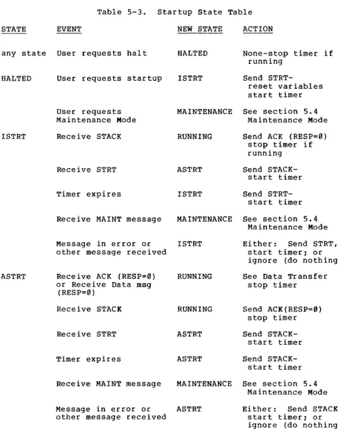
DDCMP Specification 4.0 OPERATION
Page 31
5.0 OPERATION
The DDCMP functions may be grouped into three areas: Framing, Link Management, and Message Exchange. These functional components are:
Framing
Link Management
Message Exchange
5.1 Framing
The process of locating the beginning and end of a message. It may involve bit, byte, and message
synchronization. Once framing is accomplished the protocol operates at the logical message level, both sending and receiving message blocks.
The process of controlling the transmission and reception on links connected to two or more transmitters and/or receivers on a common signal channel. This is true of half-duplex and multipoint links. There must be an orderly mechanism for the proper receiver to identify its data and for only one transmitter on a common signal channel to be active at a given time.
The process of transferring user data over the link sequentially and without bit errors. DDCMP is a positive acknowledgment retransmission protocol, returning an indication to the transmitter for each message that has been successfully received.
The basic concepts of framing were presented in Section 2.5. This section discusses the specific details of framing for each link type on which DDCMP operates. Framing occurs at the bit, byte, and message levels.
Bit framing is handled by the modems and interfaces, and is not a part of this standard.
5.1.1 Byte Framing - This process entails framing on the proper 8-bit byte sequence so that bits may be grouped into meaningful 8-bit bytes. Byte framing differs for each type of link employed. The byte framing procedures for asynchronous, synchronous, and parallel links are provided below.
DDCMP Specification 4.0 OPERATION
Page 32
binary 1 condition. For sending a byte (or a bits) over the line, the framing technique used is based on a start and a stop bit placed at each end of the byte.
The presence of the start bit is recognized by the receiving computer as a change from the 1 to 0 state. This change (a) starts the receiver sampling the line at preset timing
intervals and (b) tells the receiver that the next a bits will be the data byte followed by a ninth bit, the stop bit. An important consideration is that there is no framing until the start bit is received for each byte.
A potential problem on asynchronous links is that framing may be lost during the transmission of multiple abutting bytes (i.e., where the next start bit immediately follows the preceding stop bit). If the receiver shifts in bit timing, it may time its search for a start bit at the exact interval when a data bit with the same value as the start bit is received. The receiver would then think that the next eight bits were data, look for the stop bit, and wait for the next start bit to reframe. The error will be caught by the block check for the current message but may lead to misframing and missing the next message if uncorrected.
The solution to synchronization on asynchronous links specifies that the transmitter must either send an all ones byte DEL (value 255. or 377 octal) or idle the link for 10 bit times when resynchronization is required. This technique will guarantee proper byte framing for the next byte at the receiver. The receiver does not look for this DEL, i t simply causes proper framing on the next byte. If the DEL is received, it is ignored when resyncing. On asynchronous links bytes always abut due to their independence from each other in time. So resynchronization is required only for error recovery and is not required preceding messages where
the link has just been idle for some time.
2. Synchronous Links. DDCMP operates on serial synchronous links using a-bit bytes. Bit timing is provided by the modem or superimposed on the data signal. On synchronous links, byte framing is established by searching for a unique 8-bit pattern or sequence in the bit stream. Once this is found every 8 bits forms the next byte. This pattern is called the SYN byte (value 150. or 226 octal). The receiver must locate and lock on to a sequence of two consecutive SYN bytes to achieve byte synchronization. The transmitter must send four or more SYN bytes to allow for the loss from missynchronization and hardware interface constraints. Additional SYN bytes are passed over on receive while searching for the first non-SYN byte. This sequence of 4 or more SYN bytes is the synchronous synchronization sequence.
Since timing between either abut (i.e.,
bytes is the first
DDCMP Specification 4.0 OPERATION
Page 33
immediately follows the last byte of the current message with no intervening time) or byte framing is assumed lost following the end of the current message. The next message must reestablish or resynchronize byte framing at the receiver. This resynchronization requires the next message to be preceded by a synchronization sequence. On some communication interfaces (usually block-oriented or DMA type) received data may be buffered in the device and by the time the software driver determines that the next message does not abut, the device may have buffered many bytes further ahead on the link. Therefore, on synchronous links, a long synchronization sequence is required when messages do not abut to account for the potential buffering in the interface. This value is the number passed over or buffered by the device plus 4 more for resynchronization. Current devices and programming techniques have set the long sync sequence to 8 or more SYN bytes. This allows for 4 bytes of buffering in the device followed by the 4-byte SYN sequence. A feature has been included in DDCMP that can be used to reduce the length of this sequence and improve efficiency of the protocol. This is implemented via the QSYNC or quick sync flag present in all messages.
If set in a message, the QSYNC flag notifies the receiver that the next message will not abut and the synchronization sequence preceding the next message may be the short sequence. When the transmitter knows the next message will not abut the current message, it may set the QSYNC flag. The receiver seeing this may set resynchronization on the device immediately following the current message without looking ahead into the next message (and possibly requiring a long synchronization sequence due to device buffering). This allows the receiver to sync on a short sequence. A long sequence may always be used~ the additional sync bytes are simply ignored.
3. Parallel Links. If the transmission rate over the link is a multiple of 8 bits, then byte framing is inherent on the
link. If the transmission rate is a multiple of some other number of bits, then other means must be sought to achieve byte framing. Such a way is not currently specified by this standard.
nDCMP Specification 4.0 OPERATION
1. If the starting byte is SOH or DLE then: the next will complete the message header, followed by 2 header block check (CRC), followed by COUNT bytes
(where COUNT is the 14-bit field following SOH followed by 2 bytes of data block check.
Page 34
5 bytes bytes of of data or DLE) ,
2. If the starting byte is ENQ then: complete the message, followed check.
the next 5 bytes will by 2 bytes of header block
The data field is totally transparent. No pattern searching is done once the starting byte is found. If the header CRC is in error the framing stops and resynchronization will occur (see section 5.3, Message Exchange). If the station is a multipoint tributary and the ADDR in the header does not match the station address the tributar still tracks the message by framing i t (see section 5.2, Link Management) •
In some cases, where errors caused by the loss of synchronization on synchronous links have resulted in one or more bits being either removed or added, the performance of the eRC block check is not as good as in cases of simple bit changes. To increase the error detection capability in these cases, the following additions should be made to the techniques described above (synchronous only):
Transmission - Whenever idling the link, ensure that the transmission ends with 8 or more 1 bits (DEL bytes). This is a restriction on the optional leader preceding a sync sequence separating messages, and on the trailer, before shutdown, where the modern may require 2 or more DEL bytes.
Reception - (Optional to achieve better detection capability). After receiving the end of a data message with a valid CRC, do not process until one more byte is received. Discard the message (treat as a data CRC error) if this byte is not either: DEL, SYN, SOH, ENQ, or DLE.
5.1.3 Synchronization - Synchronization is the process of establishing both byte and message framing.
5.1.3.1 Receiver Synchronization - Synchronization takes place at the receiver under the following conditions:
1. Initially on receiver start-up, or for half-duplex and multipoint operation on link turnaround or selection (see
section 5.2, Link Management).
2. If messages do not abut (i.e., the next abutting byte is no~
DDCMP Specification 4.0 OPERATION
3. If the QSYNC flag is set in the resynchronize at the end of the message.
current
Page 35
message,
4. If a block check (CRC) error or other error occurs that might have caused synchronization to be lost (e.g., receiver overrun) •
The receiver should track the link as much as possible and only resynchronize when synchronization may have been lost. This will increase the efficiency in receiving abutting messages and reduce the chance of synchronizing on a false message inside a data message (the aliasing problem).
5.1.3.2 Transmitter Synchronization - The transmitter will send a synchronization sequence prior to transmitting messages under the following conditions:
1. Initially on transmitter start-up or turnaround (half-duplex and multipoint) •
following link
2. If a multipoint control station when changing the ADDR in messages to different tributaries.
3. If messages do not abut (synchronous mode only - they always abut in the asynchronous mode) .
4. If QSYNC is set in the current message, precede the next message with the sync sequence.
5. In the next message sent after receiving a NAK.
6. Preceding all control (ENQ) messages except ACK. A synchronization sequence will also precede an ACK if one of the other conditions is satisfied.
7. Preceding all maintenance mode (MAINT) messages.
8. Preceding all messages with the SELECT flag on (see section 5.2, Link Management).
9. Preceding the next message if a hardware/driver error (e.g., overrun) occurs while transmitting the current message.
OOCMP Specification 4.6 OPERATION
Page 36
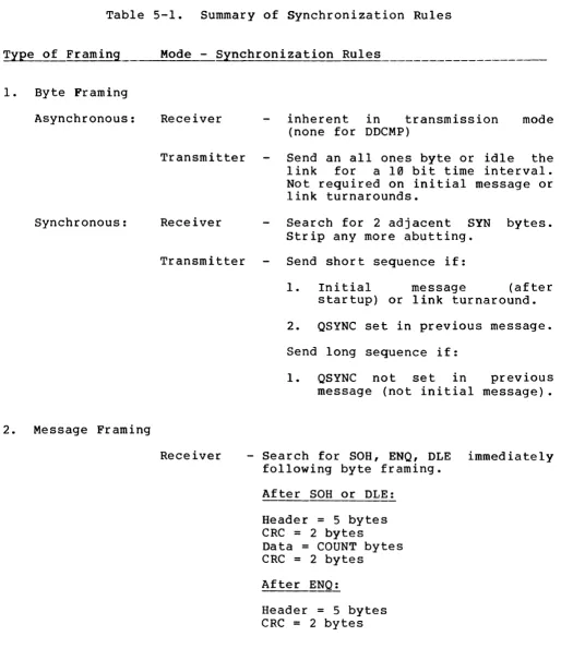
5.1.3.3 Synchronization Rules - Table 5-1 Synchronization rules.
summarizes the DDCMP
Table 5-1. Summary of Synchronization Rules
Type of Framing
1. Byte Framing
Asynchronous:
Synchronous:
2. Message Framing
Mode - Synchronization Rules
Receiver
Transmitter
Receiver
Transmitter
Receiver
inherent in transmission (none for DDCMP)
mode
Send an all ones byte or idle the link for a 10 bit time interval. Not required on initial message or link turnarounds.
Search for 2 adjacent SYN bytes. Strip any more abutting.
Send short sequence if:
1. Initial message (after startup) or link turnaround.
2. QSYNC set in previous message.
Send long sequence if:
1. QSYNC not set in previous message (not initial message).
- Search for SOH, ENQ, OLE immediately following byte framing.
After SOH or OLE:
Header = 5 bytes eRC
=
2 bytesData = COUNT bytes CRe = 2 bytes
After ENQ:
[image:37.613.54.568.148.742.2]DDCMP Specification 4.0
OPERATION Page 37
Transmitter - Send message immediately after byte framing sychronization sequence.
Notes:
1. The recommended short synchronization sequence is 4 or more SYN bytes.
2. The recommended long synchronization sequence is 8 or more SYN bytes.
3. In response to a NAK, to assure that a receiver is in the reframing mode and has not already framed on an erroneous message, the transmitter may optionally increase the synchronization sequence to:
a. 8 or more all ones bytes (DEL bytes
asynchronous mode. 255. ) for the
b. 10 or more SYN bytes (150.) for the synchronous mode.
4. A simple implementation may precede all messages with a sync sequence. It may also always send a long synchronization sequence, at some cost in time and efficiency, since extra SYN bytes are ignored.
5. If modems and/or interfaces require PAD sequences to clear them and to assure transmission of the last message byte prior to transmitter shutdown they should use all ones bytes
(DEL bytes - 255.) for synchronous and asynchronous modes.
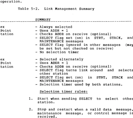
5.2 Link Management
Link management is the process of controlling the transmission and reception of data on links where there may be two or more transmitters and/or receivers actively connected to the same signal channels. This will be true of half-duplex, point-to-point links, as well as full-and half-duplex multipoint links. On half-duplex links, only one transmitter may be active at a time; on full-duplex links, only one transmitter may be active in each direction on the link at a time.