Real Time Image Feature Extraction Hardware
Jibu J V1, Sherin Das2, Nadheera K M3, Sajikumar T V4
1
Assistant Professor, College of Engineering, Chengannur,
2
HSST Computer Science.
3
Associate professor, Govt Engineering College, Barton Hill.,
4
Assistant Professor, College of Engineering, Chengannur.
Abstract: In recent times object identification has become a demanding field for the research community and the market. Of the available object recognition algorithms SIFT (Scale Invariant Feature Transform) has got major attention in the market. The SIFT features are invariant to image scale and rotation, and are shown to provide robust matching across a substantial range of affine distortion, change in 3D viewpoint, and change in illumination. In addition to object identification a large no of security, and forensic applications use the SIFT features. But has several constraints in real time applications. SIFT descriptor generation is really a time consuming operation which limits its real time application. For real time application it should not take more than 30 ms for 30 frames/sec video. Here we are proposing a hardware architecture for generating SIFT features, which are 128 byte long. Results obtained in Xilinx ISE is found to be better than the simulation result obtained using MATLAB R2012a,in terms of speed. Parallelism is introduced between Key Point Detection module and Magnitude and Orientation calculation .Measures were taken to reduce the hardware requirement. Here SIFT descriptor is generated for a gray scale image. The same thing can be extended for video.
Keywords: Sift, Vlsi, Image Feature Extraction Hardware, Computer Vision, Gaussion Pyramid
I. INTRODUCTION
Now different complex problems in image processing has become simple with the development of image processing algorithms and advance in hardware technologies. similarly the solutions for image matching and object detection also become simple. Even though these algorithms works good in pc their real time application on mobile robot platform has different constraints. Here we are proposing a customized architecture to implement such an algorithms in real time. Due to its high matching capability Scale Invariant Feature Transform (SIFT) has many advantages over its predecessor Harris and Stephens detector[1] .In 2004 David G Lowe [2]presented this method of extracting features from images. This proposed architecture can be completely embedded on a FPGA. In 2008 VanderleiBonato and Eduardo Marques [3]proposed an architecture which takes 33ms to extract the SIFT features for an image of size 320X240.Here the orientation and gradient magnitude is calculated using CORDIC algorithm. In 2009 Lifan Yao and HaoFeng[4] came out with new idea of finding the sift features ,which reduces to a 72 bit descriptor from the original 128 bit descriptor. here the descriptor generation is done with a polar arrangement. In 2014 Jie Jiang, Xiaoyang Li and Guangjun Zhang[1] proposed a novel window dividing technique which improves the speed of operation and decreases the hardware requirement. In this architecture the floating point operation is avoided for simplicity. and the descriptor dimension is again 128 bit. Two identical random access memories are adopted with ping–pong operation to execute the key point detection module and the descriptor generation module in task-level parallelism. This paper is organized as follows. Section II deals with the SIFT algorithm proposed by Lowe[2].Section III gives our proposed architecture. Section IV shows the experimental results. Finally the conclusion is given in section V .
II. SIFT ALGORITHM BASICS
The SIFT algorithm consist of four parts .The first one is the formation of Difference of Gaussian Pyramid. Second step is identification of key points. Then we have to calculate the gradient magnitude and Orientation. Finally we have to Generate the SIFT descriptor.
A. Formation of Difference of Gaussian Pyramid.
L(x, y ,σ) = G(x, y ,σ) *I(x, y )...(1) D(x, y ,σ) = L(x, y ,kσ) - L(x, y ,σ)...(2) whereG is the Gaussian kernel with a scale of σ is shown as G(x, y ,σ) = (1/2πσ2)e-((x2+y2)/2σ2)Which is equivalent to
DOG ==(k−1)σ2∇2
G ...(3)
The convolution of input image I(x,y) with variable scale Gaussian Kernel produces a space of blurred images with amount of blur
depends on scale factor (σ).In this way a stack of Gaussian blurred images are produced which constitute one octave. A Gaussian
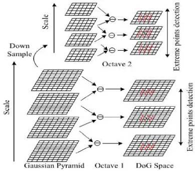
[image:3.612.114.503.253.594.2]Pyramid is formed by multiple octaves with different image sizes. That is for each successive octave the image is down sampled. No of octaves and scales effects the robustness and complexity. Thus the octave formation is a sequential operation. That is the next scale in each octave is formed only after the completion of the previous smoothing operation by the Gaussian function. So it is a time consuming part. The process is explained in Fig(1).
Fig 1 Gaussian pyramid formation
For each octave of scale space, the initial image is repeatedly convolved with Gaussians to produce the set of scale space images shown on the left. Adjacent Gaussian images are subtracted to produce the difference-of-Gaussian images on the right. After each octave, the Gaussian image is down-sampled by a factor of 2, and the process repeated. In addition, the difference-of-Gaussian function provides a close approximation to the scale-normalized Laplacian of Gaussian, σ2∇2
G, It can be showed that the normalization of the Laplacian with the factor σ2 is required for true scale invariance. In detailed experimental comparisons, we can prove that the maxima and minima of σ2∇2
B. Identification Of Key Point
[image:4.612.135.468.599.724.2]The maxima and minima of the Difference of Gaussian images are detected by comparing a pixel (marked with X) to its 26 neighbors as shown in fig(2) .This approach gives rise to a lot of Keypoints depending on the image size. Often quality of keypoints is more important than the quantity for reliable object recognition. The features that have greater probability to be found in the other version of the image exhibit better quality. For ensuring the stability of keypoints, the local extrema are compared with a minimum threshold value. The extremathat have relatively higher minima or maxima value pass the threshold test and are considered, while the weak keypoints having low contrast are discarded, resultingin less but more stable candidates
Fig 2 Finding feature points
C. Calculation Of Gradient Magnitude And Orientation
The magnitude-orientation histogram is used to describe a feature point, which is computed from the gradient magnitude and orientation of the neighbor pixels around the candidate feature point. For a given pixel (x,y) the gradient magnitude and orientation are computed as
m(x,y)=((L(x+1,y)-L(x-1,y))2+(L(x,y+1)-L(x,y-1))2)1/2...(4)
Θ(x,y)=tan-1((L(x,y+1)-L(x,y-1)/(L(x+1,y)-L(x-1,y))) ...(5)
D. Key Point Descriptor Generation
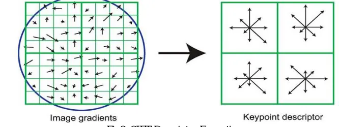
A keypoint descriptor is created by first computing the gradient magnitude and orientation at each image sample point in a region around the keypoint location, as shown in fig(3). These are weighted by a Gaussian window, indicated by the overlaid circle. These samples are then accumulated into orientation histograms summarizing the contents over 4x4 subregions, as shown on the right, with the length of each arrow corresponding to the sum of the gradient magnitudes near that direction within the region.
E. Descriptor Matching.
The suitable match for each key point in the test image is found by finding its nearest neighbor from the data base of key points of trainimage. The nearest neighbor is defined as the keypoint with minimum Euclidean distance for the descriptor vector. Since the test image has the background clutter many key points does not have correct matches in the training data base. Another method is to compare the distance of closest neighbor to that of second closest neighbor The matches are identified by finding the nearest neighbors of each key point from the first image among those in the second image, and only accepting a match if the distance to the closest neighbor is less than 0.6 of that to the second closest neighbor .The threshold of 0.6 can be adjusted up to select more matches or down to select only reliable. In Matlab it is easier to compute dot product than Euclidean distances. Note that the ratio of angles is a close approximation to the ratio of Euclidean distances for small angles .The nearest neighbor is found by the following method .For each descriptor in the first image, select its match to second image. first we have computed the matrix transpose of training image and find the dot product with the test image. then take the inverse cosine and find the square root of it. then check whether the nearest neighbore has angle less than distance ratio times second.
III. PROPOSED ARCHITECTURE
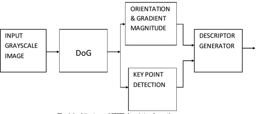
[image:5.612.119.529.460.643.2]SIFT descriptor generation is really a time consuming operation which limits its real time application. For real time application it should not take more than 30 ms for 30 frames/sec video The scope of this thesis is to implement part of the SIFT software algorithm in hardware on a FPGA. The designed architecture should comprise dedicated hardware units for the computationally intensive part of the SIFT algorithm. The design is synthesizable, adaptable, generic and demand few FPGA resources. It may be adaptable to different number of octave and scales. One important question in video processing is to decide which algorithm parts should run on software processors and which ones should be implemented in hardware, for instance FPGA or ASIC. The input images are provided by a camera with a jpg format 320X240 with an 8-bit grey scale image and a hardware module which stores the images from the camera on the external RAM. In order to access and store the input images and output data, a pre-developed cache hardware module will be utilized. The output data will be stored on the external RAM memory connected with the FPGA using a multi-port memory controller IC provided by Xilinx..The main aim of this thesis is to propose an architecture for finding a SIFT descriptor so that it can be used for real time application. The hardware implementation of SIFT algorithm includes four different blocks .The first block form the Scale space and calculate the DoG. The other two blocks run in parallel ,to speed up the process . Key point detection part and gradient magnitude and orientation part run in parallel . Next block is the computationally intensive part of SIFT algorithm '' Descriptor Generation" part.
Fig 4 Architecture of FIFT descriptor formation
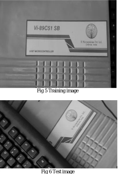
A. Input Grayscale Image
Fig 5 Training image
Fig 6 Test image
[image:6.612.202.408.540.717.2]In this way we can improve the speed of operation of Gaussian space formation at the cost of increased hardware .That is in the original architecture only one Gaussian kernel is needed but here 8 Gaussian kernel is needed or the no of σ's needed to store is high.But the speed of operation increasesOnce the Gaussian pyramid is constructed the next step is to compute the DoG pyramid. This step is significantly improved in terms of computational cost by Lowe’s method where it is computed by taking the difference between the two adjacent scales separated by a constant multiplicative factor k.ndidate features are detected from the DoG scale-space by finding the local extrema. In order to detect the local maxima or minima from D(x, y, σ) each sample in the DoG image is compared to its eight neighbors in the current image and nine corresponding neighbors at the adjacent scales. A sample point is selected
as a candidate keypoint if it is either larger or smaller than all these neighbors These extrema are computed for all the octaves in the similar manner.
B. Orientation And Magnitude Calculation
The gradient orientation of sample point around the key point region is used to create the orientation histogram. The orientation histogram has 36 bins, which cover the 360° range of orientations. Gradient magnitude of each sample, added to the histogram, is scaled by a Gaussian weighted kernel that is 1.5 times of the scale of the key point. Peaks in the orientation histogram correspond to dominant directions of local gradients.
C. Descriptor Generator
The descriptor is generated using the method as explained by Lowe[1]. The descriptor is formed from a vector containing the values of all the orientation histogram entries, corresponding to the lengths of the arrows on the right side of figure 3. It is proved that the best results are achieved with a 4 × 4 array of histograms with 8 orientation bins in each. Therefore, the experiments in this paper use a 4 × 4 × 8 = 128 element feature vector for each keypoint.
IV. RESULT
The training image has 564 no of key points where as test image has 630 feature points .Simulation of SIFT algorithm is done with MATLAB R2012. These results were taken as a reference for the hardware implementation. The simulation result is given below It takes 40ms to run this simulation in Matlab.
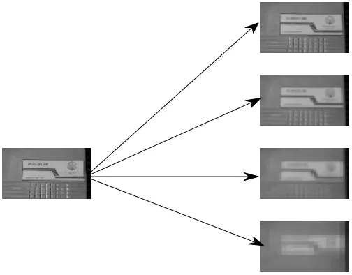
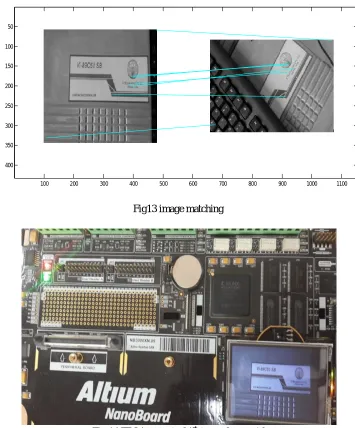
[image:7.612.188.440.499.696.2]Fig 11 shows pyramid formed by training image. All the stages are formed directly from the given image. Similarly fig 12 shows pyramid formed by test image .Fig13 shows the matching of the key points in both images .Fig 14shows the pyramid formed in the Altium Nano Board 3000.Table 1 gives the FPGA hardware utilization details.
Fig 12 Gaussian pyramid of test image
Fig13 image matching
100 200 300 400 500 600 700 800 900 1000 1100
50
100
150
200
250
300
350
[image:8.612.128.483.300.728.2]TABLE I FPGA utilization
Parameter Value
Number of Slices 7400
Number of Slice flipflops 6028
Number of 4 input LUTs 9746
Number of 2 input LUTs 9852
Number used as RAM 340
Number used as ROM 78
V. CONCLUSION
The SIFT algorithm is invariant to image scale and rotation, and are shown to provide robust matching across a substantial range of affine distortion, change in 3D viewpoint, addition of noise, and change in illumination. The features are highly distinctive, in the sense that a single feature can be correctly matched with high probability against a large database of features from many images. It has several application in the following areas. Robot navigation, Panoramic photograph, Object detection and recognition, Sports and Wild life Censes..This architecture runs in 29 ms which can be used for real time application. This can be extended to different variants of sift like CSIFT[5],SURF[6],PCA SIFT[7],.
REFERENCES
[1] Jie Jiang, Xiaoyang Li, and Guangjun SIFT Hardware Implementation for Real-Time Image Feature Extraction IEEE transactions on circuits and systems for video technology, vol. 24, no. 7, july 2014.
[2] D. G. Lowe, “Distinctive image features from scale-invariant key points,” Int. J. Comput. Vis., vol. 60, no. 2, pp. 91–110, Jan. 2004.
[3] V. Bonato, “A parallel hardware architecture for scale and rotation invariant feature detection,” IEEE Trans. Circuits Syst. Video Technol., vol. 18, no. 12, pp. 1703–1712, Dec. 2008
[4] Lifan Yao , HaoFeng , Yiqun Zhu , Zhiguo Jiang, Danpei Zhao, WenquanFeng.An Architecture of Optimised SIFT Feature Detection for an FPGA Implementation of an Image Matcher. 978-1-4244-4377-2/09/ 2009 IEEE .
[5] Abdel-Hakim, A.E., Farag, A.A. (2006). CSIFT: A SIFT descriptor with color invariant characteristics. In Computer Vision and Pattern Recognition (CVPR 2006), 17-22 June 2006. IEEE, Vol. 2, 1978-1983.
[6] Bay, H., Tuytelaars, T., Gool, L.V. (2006). SURF: Speeded up robust features. In Computer Vision – ECCV 2006 : 9th European Conference on Computer Vision,7-13 May 2006. Springer, Part II, 404-417.