Effect of Fillet Radius on Stress Generated in
Double Fillet Weld Root and Toe
Nancy Mary Prakash1, Arun Singh Kushwah2 1
M. Tech Scholar, Department of Mechanical Engineering, ITM University, Gwalior, (M.P.), India
2
Assistant Professor, Department of Mechanical Engineering, ITM University, Gwalior, (M.P.), India
Abstract: FEA (Finite element analysis) of the stress generated in the double fillet weld joint has been conducted for different fillet radius values. Fillet weld considered in the present study is three dimensional and have two-vertical plates which are attached to a horizontal plate by welding. Analysis of stress in the weld toes and weld root has been studied and shown. Five different sets of load values varying from 100N to 10000N have been considered on the left-hand side and right-hand side of the horizontal plate. Fillet radius has been varied from 3mm, 5mm, 7mm to 9mm to study its effect. Meshing is very important stages which affect the finite element results by a large amount. As meshing plays a good role in the FEA analysis, fine meshing near the weld toes and weld root has been adopted for accurate results. Study reveals that weld roots and toes are the zone where maximum amount stress developed which can also called as stress concentration zone. With increment in load stress generated in the weld toes and weld roots areas increases continuously. Total deformation increases with load. Increasing the fillet radius reduces the amount of stress and strain developed on the weld.
I. INTRODUCTION
Two parts joined together by application of localised heat or fusion is called a weld they joined together either with or without the pressure or filler material application. Amount of heat necessary for fusion is attained by burning of gas or an electric arc. Weld means joining of two metals by heat while joint means a point where two parts connects together they can be anything. Most vital components of a welding assembly are weld toe and weld roots where maximum amount of stress and failure occurs. It is practically impossible to have weld which have 100% efficiency.
Welding is a complex procedure which varies the weld joint physical, mechanical and chemical properties. They have numerous applications. For example like repairing or uniting the two broken or torn parts to make material homogeneous throughout the section. Goldak et al1 in 1984 conducted their study on FEM of welding heat sources.
Goldak’s new method has shown to be more accurate than previous methods such as the Pavelic2 disc method, as well as the previously mentioned Rosenthal theory for heat distribution in welding. Michaleris et al3 in 1999 investigated the use of the thermal tensioning technique to reduce residual stress and distortion in welding. Barsoum and Lundback4 in 2009 conducted 2D and 3D FE simulation of fillet weld to study the residual stresses formation. Picon and Canas5 in 2009 studied about two strength criteria utilized for fillet welds ISO and Eurocode-3.
Aarbogh et al6 in 2010 conducted validation of FEM codes of welding deformation. Jose-V and Selvakumar7 in 2012 studied about the effect of fillet radius on tensile and compressive load for fillet weld joint. Tonkovic et al8 in 2012 conducted experimental and numerical modelling of T-type fillet weld joint process to study the residual stresses and distortion. Xiao et al9 in 2012 studied fatigue strength of transverse fillet weld under bending loads.
Tahami and Asl10 in 2013 conducted AISI 304 stainless steel T-shape fillet weld numerical and experimental investigation. Wang et al11 in 2013 conducted temperature simulation and analysis of sleeve fillet weld used in multi-pass welding. Cerit et al12 in 2014 conducted fillet weld fracture mechanism design and reliability assessment under tension and torsion loading condition of cylindrical fillet weld. Dutta and Narendranth13 studied the thermal cycle effect on the GTA high carbon steel weld joint with temperature dependent process parameter.
II. MODELLING
Figure 1 Weld with and without weld joints
III. MATERIAL PROPERTIES
[image:3.612.154.459.351.460.2]Two different material steel and Epoxy has also been considered in the present study to see the effect of the material on the on the stress generation, strain generation and total deformation. Weight study has also been conducted in the present problem. Table 1 shows the mechanical properties of steel and Epoxy considered.
Table 1: Mechanical properties of steel
Properties Steel Epoxy
Young’s modulus (E) 2E11 Pa 85E12 Pa
Poisson ratio 0.3 0.23
Tensile Ultimate strength 4.6E8 Pa 9 E8 Pa Tensile yield strength 2.5E8 Pa 1470 Pa
Density 7850 Kg/m3 2160 Kg/m3
IV. RESULT AND DISCUSSION
In this work effect of different loading conditions and fillet radius on the total deformation, equivalent von-mises stress and equivalent von-mises strain have been studied in detailed. Figure 2 shows the boundary condition applied on the fillet weld. On the right and left side of the horizontal plate tension force has been applied while vertical plates have been kept fixed.
[image:3.612.132.488.506.715.2]Five different sets of load values varying from (100N to 10000N) have been considered on the left-hand side and right-hand side of the horizontal plate. Table 2 shows the five different set of loading values considered. Fillet weld radius has been varied from (3mm, 5mm, 7mm and 9mm) to see its effect on the stress generation, strain generation and total deformation.
Table 2: Loading values considered on the fillet weld
Set No. 1 2 3 4 5
Load (Tensile)
Left 100N 100N 1000N 1000N 10000N
Right 100N 1000N 100N 1000N 10000N
A. Effect of the fillet radius
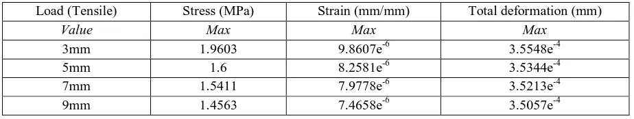
To study the effect of the fillet radius set-4 (1000N and 1000N) has been considered and values of fillet radius has been varied from 3mm, 5mm, 7mm to 9mm. Table 3 shows the values of the stress, strain and total deformation developed for the steel material.
Table 3: Stress, strain and total deformation for steel under (1000N and 1000N) load
Load (Tensile) Stress (MPa) Strain (mm/mm) Total deformation (mm)
Value Max Max Max
3mm 1.9603 9.8607e-6 3.5548e-4
5mm 1.6 8.2581e-6 3.5344e-4
7mm 1.5411 7.9778e-6 3.5213e-4
[image:4.612.77.538.421.538.2]9mm 1.4563 7.4658e-6 3.5057e-4
Figure 3, 4 and 5 shows the stress, strain and total deformation generated for all fillet radiuses considered in the present study. Steel as a material has been considered for these figures. Figure 6 to 8 represents a better view of studying the effect of fillet radius on the stress, strain and total deformation generated under the same loading condition. From the figures 6-8 it can be noticed that maximum munt of stress generated is near the weld are. It can be easily observed that with increment in the fillet radius or increasing the size of fillet reduces the amount of stress, strain and total deformation developed on the fillet weld.
(a) 3mm fillet radius (b) 5mm fillet radius
(c) 7mm fillet radius (b) 9mm fillet radius
[image:4.612.84.527.569.700.2](a) 3mm fillet radius (b) 5mm fillet radius
[image:5.612.96.523.79.206.2](c) 7mm fillet radius (b) 9mm fillet radius
Figure 4: Von-mises strain under the load of 1000N and 1000N
(a) 3mm fillet radius (b) 5mm fillet radius
(c) 7mm fillet radius (b) 9mm fillet radius
Figure 6: Stress vs. fillet radius Figure 7: Strain vs. fillet radius
Figure 8: Total deformation vs. fillet radius
[image:6.612.196.413.301.479.2]To study the effect of the fillet radius set-4 (1000N and 1000N) has been considered and values of fillet radius has been varied 3mm, 5mm, 7mm and 9mm. Table 4 shows the values of the stress, strain and total deformation developed for Epoxy material.
Table 4: Stress, strain and total deformation for Epoxy under (1000N and 1000N) load
Load (Epoxy) Stress (MPa) Strain (mm/mm) Total Deformation (mm)
Value Max Max Max
3mm 2.0326 2.4082e-8 8.1773e-7
5mm 1.5657 1.8661e-8 8.127e-7
7mm 1.484 1.8058e-8 8.0995e-7
9mm 1.4031 1.6945e-8 8.0696e-7
Figure 9 to 11 shows the amount of stress, strain and total deformation generated in the fillet weld made of Epoxy material. Figure 9 shows the comparison of the stress generated in the fillet weld made of steel and Epoxy material. It can be observed that with increment in the fillet radius amount of stress developed in the fillet weld made of Epoxy material is decreases by greater amount when compared with fillet weld made of steel.
Fillet radius (mm)
S tr e s s (M P a )
2 3 4 5 6 7 8 9 10
1.4 1.5 1.6 1.7 1.8 1.9 2
fillet radius (mm)
S tr a in (m m /m m )
2 3 4 5 6 7 8 9 10
7E-06 7.5E-06 8E-06 8.5E-06 9E-06 9.5E-06 1E-05
fillet radius (mm)
T o ta l d e fl e c ti o n (m m )
2 3 4 5 6 7 8 9 10
[image:6.612.76.537.558.642.2]Figure 9: Comparison of Stress for steel and Epoxy with fillet radius
Figure 10: Strain with fillet radius for Epoxy material
Figure 11: Total deformation with fillet radius for Epoxy material
B. Effect of the Loading Condition
To study the effect of the load one fillet radius (5mm) has been considered and values of load has been varied. It can be observed from the table that with increment in the load values amount of stress, strain and total deformation generated in the weld area increases.
Table 5: Stress, strain and total deformation for steel for different load values Set No.
(Material-Steel)
Load (Tensile) Stress (MPa) Strain (mm/mm) Total Deformation (mm)
Left Right Max Max Max
1 100N 100N 0.160 8.258e-7 3.534e-5
2 100N 1000N 1.636 8.433e-6 3.647e-4
3 1000N 100N 1.636 8.433e-6 3.647e-4
4 1000N 1000N 1.600 8.258e-6 3.534e-4
5 10000N 10000N 17.39 8.768e-5 3.786e-3
Fillet radius (mm)
S tr e s s (M P a )
2 3 4 5 6 7 8 9 10
1.3 1.43 1.56 1.69 1.82 1.95 2.08 Steel Epoxy
fillet radius (mm)
S tr a in (m m /m m )
2 3 4 5 6 7 8 9 10
1.6E-08 1.8E-08 2E-08 2.2E-08 2.4E-08 2.6E-08
fillet radius (mm)
T o ta l d e fl e c ti o n (m m )
2 3 4 5 6 7 8 9 10
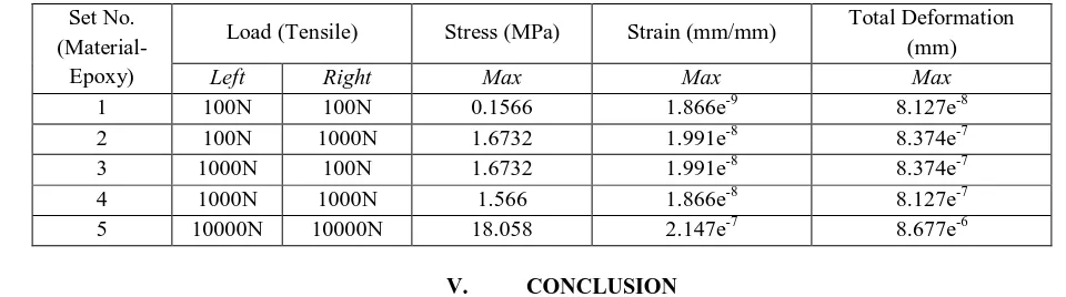
[image:7.612.193.413.319.490.2] [image:7.612.71.539.598.708.2]Table 6: Stress, strain and total deformation for Epoxy for different load values Set No.
(Material-Epoxy)
Load (Tensile) Stress (MPa) Strain (mm/mm) Total Deformation (mm)
Left Right Max Max Max
1 100N 100N 0.1566 1.866e-9 8.127e-8
2 100N 1000N 1.6732 1.991e-8 8.374e-7
3 1000N 100N 1.6732 1.991e-8 8.374e-7
4 1000N 1000N 1.566 1.866e-8 8.127e-7
5 10000N 10000N 18.058 2.147e-7 8.677e-6
V. CONCLUSION
A. Three-dimensional double fillet weld finite element analysis has studied on weld toes and root areas. B. With increment in load stress generated increases continuously.
C. Total deformation increases with increment in load.
D. Increasing the fillet radius reduces the amount of stress and strain developed on the weld. E. With increment in the fillet radius, amount of deformation generated is reduced.
REFERENCES
[1] Goldak J., Chakravarti A., Bibby M., 1984, “A New Finite Element Model for Welding Heat Sources”, Metallurgical Transaction B, Vol. 15B, p. 299-305. [2] Pavelic V., R. Tanbakuchi, O. A. Uyehara, P. S. Myers, 1969, “Experimental and Computed Temperatures Histories in Gas Tungsten Arc Welding of Thin
Plates”, Welding Journal Research Supplement, Vol. 48, p. 295-305.
[3] Michaleris P., Dantzig J., Tortorelli D., 1999, “Minimization of Welding Residual Stress and Distortion in Large Structures”, Welding Research Supplement, p. 361-366.
[4] Barsoum Z., Lundback A., 2009, “Simplified FE Welding Simulation of Fillet Welds-3D Effects on the Formation Residual Stresses, Engineering Failure Analysis, Vol. 16, p. 2281-2289.
[5] Picon R., Canas J., 2009, “On Strength Criteria of Fillet Welds”, International Journal of Mechanical Sciences, Vol. 51, p. 609-618.
[6] Aarbogh H.M., Hamide M., Fjaer H.G., Mo A., Bellet M., 2010, “Experimental Validation of Finite Element Codes for Welding Deformations”, Journal of Materials Processing Technology, Vol. 210, Issue. 13, p. 1681-1689.
[7] Jose-V S., Selvakumar M. J., 2012, “An Overview of Fillet Weld Joints Subjected to Tensile and Compressive Loads”, International Journal of Science and Research, Vol. 3, Issue. 5, p. 260-265.
[8] Tonkovic Z., Peric M., Surjak M., Garasic I., Boras I., Rodic A., Svaic S., 2012, “Numerical and Experimental Modelling of a T-joint Fillet Welding Process”, 11th International Conference on Quantitative Infra-Red Thermography, 2012.
[9] Xiao Z.G., Chen T., Zhao X-L., 2012, “Fatigue Strength Evaluation of Transverse Fillet Welded Joints Subjected to Bending Loads”, International Journal of Fatigue, Vol. 38, p.57-64.
[10] Tahami F.V., Asl A.Z., 2013, “Numerical and Experimental Investigation of T-Shape Fillet Welding of AISI 304 Stainless Steel Plates, Materials and Design, Vol. 47, p. 615-623.
[11] Wang Y., Wang L., Di X., Shi Y., Bao X., Gao X., 2013, “Simulation and analysis of temperature field for in-service multi-pass welding of a sleeve fillet weld”, Computational Materials Science, Vol. 68, p. 198-205.
[12] Cerit M., Hosgor K., Ayhan A.O., 2014, “Fracture Mechanics-Based Design and Reliability Assessment of Fillet Welded Cylindrical Joints under Tension and Torsion Loading”, Engineering Fracture Mechanics, Vol. 116, p. 69-79.
[13] Dutta J. and Narendranath S., 2014, “Influence of Thermal Cycle on Temperature Dependent Process Parameters Involved in GTA Welded High Carbon Steel Joints”, International Journal of Mechanical, Aerospace, Industrial, Mechatronic and Manufacturing Engineering, Vol. 8, Issue. 9. p. 1641-1647.
[14] Krscanski S. and Turkalj G., 2014, “FEM Stress Concentration Factors for Fillet Welded CHS-Plate T-Joint”, Engineering Review, Vol. 32, Issue. 3, p. 147-155.
[15] Lu H., Dong P., Boppudi S., 2015, “Strength Analysis of Fillet Welds Under Longitudinal and Transverse Shear Conditions”, Marine Structures, Vol. 43, p. 87-106.