Load Factor Assessment and Evaluation on the
performance MIMO WCDMA Rayleigh Interference
Channel
Affum Emmanuel A.K
Department of Electrical Engineering. Kwame Nkrumah University of Science &
Technology Kumasi, Ghana
Danso Ansong, Ed
Department of Computer Science & I. T Valley View University
Oyibi – Accra, Ghana
ABSTRACT
Multiple Access Interference (MAI) is interference caused by the presence of other users in the cell. Conventional signal detectors detect only single user’s signal. When there are multiple users in the same environment, the conventional detectors treat other users’ signals as noise or interference. MAI affects system capacity and system performance. When there are more users, the MAI is high besides the performance is also affected by the near-far problem. This paper seeks to analyse the Capacity of MIMO WCDMA under various Cell Load factors. With cell loading factor of 6% and signal to noise ratio of 10dBthe 4*4 MIMO systems performed better. Besides for a cell load of 50% and a cell range of 1.02km the allowable path loss without MUD was around 98.45dB
General Terms
WCDMA; Universal mobile Telecommunications System; UMTS
Keywords
Load Factor, Multi Input Multi Output ; MIMO; Detection, Wideband Code Division Multi Access
1. INTRODUCTION
The Code Division Multiple Access (CDMA) system is an interference limited system in which link performance depends on the ability of the receiver to detect a signal in the presence of interference. Therefore, the key issue in a CDMA network design is to minimize multiple access interference that can be achieved by critical power control. Interference on the voice channels causes cross talk where the subscriber hears interference in the background due to an undesired transmission, on control channels, interference leads to missed and blocked calls due to errors in the digital signaling. Interference is more severe in the urban areas, due to the greater RF noise floor and the large number of base stations and mobiles [1] and therefore, has been recognized as a major bottleneck in increasing capacity responsible for dropped calls [2]. Sources of interference include another mobile in the same cell, a call in progress in a neighboring cell, other base stations operating in the same frequency band, or any cellular system which inadvertently leaks energy into the cellular frequency band. In [3], Heiska analyzed capacity reduction of WCDMA downlink in the presence of interference from adjacent narrow-band system by taking into account different downlink interference mechanisms such as wide-band noise from the transmitter as well as adjacent channel interference, intermodulation, and cross-modulation originating in the mobile receiver, and concluded that capacity per cell is
sensitive to the cell size, and therefore, very careful network planning is needed in order to operate the WCDMA networks efficiently. The Interference Performances, when WCDMA and HSDPA coexist as analyzed by Pei Li in [4], provided simulation results indicating that the system performance in the hybrid cells is better than the pure macro cell for WCDMA and HSDPA. After investigation of WCDMA inter-operator adjacent channel interference , Joyce et al [5], proposed a number of measures which both operators and vendors should take to avoid deadzones in an operational WCDMA network.
Extensive studies have been done by Gao Peng and the group [6] where they analyzed the interference between WCDMA and WIMAX systems to evaluate the impact of inter-system interference produced by coexistence of systems in the same geographical area in adjacent frequency and concluded that WCDMA and WiMax systems could coexist and gave the proposals of interference mitigation method in the case of coexistence of two systems. Results on the other-cell to own-cell interference values and traffic capacity for dedicated indoor WCDMA systems were presented in [7]. Also, Kiiskila and the group in [8] discussed receiver complexity and presented optimal and suboptimal spatial maximum a posteriori receivers in a concatenation of Linear Minimum Mean Square Error (LMMSE) equalizer structure for Multiple-Input-Multiple-Output (MIMO) Wideband Code Division Multiple Access (WCDMA) systems, and further, proposed that in frequency selective fading channels where LMMSE part mitigates the Multiple Access Interference (MAI) and Inter-Antenna Interference (IAI) is achieve by the spatial MAP or its approximation. Potential GPRS 900/180-MHz and WCDMA 1900-900/180-MHz Interference to Medical Devices were also investigated by Iskra et al and compared the potential for interference to medical devices from Radio Frequency (RF) fields radiated by GSM 900/1800-MHz, General Packet Radio Service (GPRS) 900/1800-MHz, and Wideband Code Division Multiple Access (WCDMA) 1900-MHz handsets. Performance analysis of MQAM for MIMO WCDMA systems in fading channels has extensively studied [10] with authors developing an analytical framework that could handle an arbitrary number of transmit and receive antennas in both open-loop and closed-loop systems with numerical results showing that the system could achieve significant performance improvement by using the combined transmit and receive antenna diversity.
employing Maximum Mobile Transmitted Power and Equivalent Isotropic radiated power (EIRP) of 21dBm and 18dBm respectively with emphasis on the interference from adjacent cells. The paper further presents simulation results to support the theoretical analysis on reverse link capacity analysis in terms of cell loading factor.
Organization: In section II, the uplink and downlink load factors and efficiency of multiuser receiver of CDMA system are analyzed. Section III focuses on the MIMO system. Intercell interference and the reverse link capacity in single-cell and multi systems are analyzed in section IV. In section V, numerical and simulation results are shown and discussed, while section VI concludes this paper.
2.
CDMA UPLINK AND DOWNLINK
LOAD FACTORS
2.1
Uplink Load Factor
The for the user is expressed as
(
)
Where is the chip rate, is the received signal power from user, the channel activity factor of user is represented by . is the bit rate of the and as
total received power including thermal noise power at the base station. Let where is the load factor of
the connection [1], then
( )
The total received interference [1], without the thermal noise , can be expressed as the sum of the total received powers from all user in the same cell
∑ = ∑ . If noise rise of the entire system
is expressed as ⁄ = ∑⁄
= ⁄ , where is the uplink load factor and is
expressed as ∑ . When approaches 1, the
corresponding noise-rise approaches infinity and the system reaches its pole capacity. If is the interference factor due to other cells, in terms of interferences from other cell, the interference factor can be expressed as
Then uplink load factor can then be written as
∑
∑
The load equation at (4) predicts the amount of noise-rise over thermal-noise due to interference, and also could be used to make semi analytical predictions of the average capacity of CDMA cell and finally could also be employed in predicting cell capacity and planning noise-rise for dimension purposes [1]. The noise-rise is equal to . The
interference margin in the link budget must be equal to the maximum planned noise-rise
2.1
Multiuser Receiver Efficiency
The interference caused by the presence of other users in the cell is called Multiple Access Interference [MAI]. Conventional signal detectors detect only single user’s signal. When there are multiple users in the same environment, the conventional detectors treat other users’ signals as noise or interference. MAI affects system capacity and system performance. When there are more users, the MAI is high [1]. The system performance is also affected by the near-far problem. The use of multiuser detection techniques has also been suggested in the WCDMA UMTS system. Multiuser detection (MUD) and interference cancellation (IC) technique improve the system performance by canceling the intercell interference. MUD also known as co channel interference suppression or multiuser demodulation exploits the considerable structure of the multiuser interference in order to increase the efficiency with which channel resources are employed [11].
Since MUD efficiency varies in different radio environment, the capacity improvement attainable by MUD is not fixed. The impact of MUD on coverage introduces a new variable to the network planning process, since MUD efficiency need to be taken into account in the coverage design. The efficiency of MUD is estimated from the load that can be supported with a specified value with a
multiuser received. In the analysis, the number of users with a RAKE receiver is represented by and those with a MUD receiver by . The efficiency of MUD receiver also denoted by at a give is [12]
) The capacity of the network MUD receiver in base
transceiver station (BTS) in terms received signal power ,
power control efficiency is expressed as
Where is thermal noise, is the intracell interference from own cell mobiles, is the interference from the mobiles not connected to this particular base station, and is the processing again. But and
hence . Therefore, substituting
it into Equation (5) and neglecting the effect of thermal noise. Equation (5) becomes
( )
Where M is the number of users associated with the BTS. Further solving equation (6) for M, will result in
[ ]
In an unloaded network, the uplink limits the achievable range and coverage, as the maximum transmission power of the mobile station is lower compared with the maximum transmission power of the base station in the downlink. In a loaded network, the downlink may limit the range if there is more load and thus more interference in the downlink than the uplink. The received signal-to-interference ratio at the base
station is given as
(2)
(3)
(5)
(6)
(1)
(7)
Where is the received energy per bit, is the intracell
interference from own cell mobiles, is the interference from the mobiles not connected to this particular base station, and is the thermal noise. In case of an unloaded network , , and the required ⁄ for
range calculations is equal to ⁄ . In the loaded network, the fraction of own-cell interference from total interference is defined as
Where ⁄ the received signal is power from one user and is the processing gain. depends upon propagation environment. The higher the path-loss attenuation factor, the higher the . can be expressed in term of as
(
)
(
)
but
therefore,
( )
( )
( )
Solving the required ⁄ in the loaded case gives
(
)
( )
The effect of the MUD receiver can be taken into account by using the efficiency of the MUD as a measure of performance of the MUD receiver. With MUD receiver, the intracell interference can be written as
and
( ) ( )
the total interference will be
[ ]
The required ⁄ in the loaded network with MUD receiver becomes
( )
( )
[
]
The transmitted power from a mobile is given as
In Equation (19) above all the terms are the same except for ⁄ , regardless of the base station receiver algorithm. is determined only from the ⁄
requirement. The decrease in the required transmission power with MUD receiver is thus given as
( )
( )
(
) [
]
( )
[ ]
3. FREQUENCY SELECTIVE MIMO
CHANNEL
The general expression of frequency-selective MIMO channel indicates signals [ ] from the input of the system at each time instant and we obtain output. Therefore, the output at time instant can be expressed as [13]
[ ] ∑ ∑ [ ] [ ] [ ]
where denotes the largest number of taps among all the
contributing channels. The channel matrix has the form [14].
[ ] [
[ ] [ ]
[ ] [ ]
]
3.1 Receiver Processing
If coherent single-user matched filter is used where the receiver is assumed to know the fading coefficients of the user of interest and the transmitted signal from each antenna [15], then an antenna will receive
Optimum decision rule selects { } that minimizes ∫ ∑ | |
(8)
(10)
(11)
(12)
(13)
(14)
(15)
(16)
(17)
(18)
(19)
(20)
(21)
(22)
(23)
(24)
According to the optimum decision rule [10] the inner product of the and is the sufficient statistic [14]. This means that the optimum rule decision for a single –user case is expressed as
̂ ( { ∑
})
Therefore, the probability of error of a MIMO system could be expressed as [14].
[ (
∑ | |∑ | | ( )
)]
4. INTERCELL INTERFERENCE
4.1 Link Capacity
Considering an omnidirection cell site serving a given set of mobiles, if mobiles are divided into two groups which are mobiles that are powered up and mobiles that are not powered up, the mobiles that are powered up are further, divided into four subgroups: Active and transmitting mobiles, Active but not transmitting mobiles (mobiles in non conversational mode), Idle and transmitting (mobiles in access mode) and Idle and not transmitting (mobiles in non access mode) [1].
Assume there are M mobiles transmitting at a given time in a cell. In a CDMA environment for each mobile, there are (M – 1) interferers. At the cell site, the average signal power received from the ith mobile is . This signal power provides
bit energy equal ⁄ where, R is the mobile
transmission rate in bps. The thermal noise power is where is the thermal noise power spectral density ), and is the spreading bandwidth. The average interference at the base station is expressed as
∑
Where, = channel activity factor.
In equation (28), assuming a perfect control in the reverse link and that the signals transmitted from all the mobiles arrived at the base station with the same received power. i.e. for
all values of i (i.e. . The total interference
and thermal noise will be
∑
Recognizing that , then becomes
The will be given as,
( )
[ ]
[ ]
Where = processing gain = ⁄ . The signal strength, S in as,
Where
From (30)
[
]
also,
⁄
⁄
Let represent the interference factor from other cells (31) can be expressed as
[ ]
Include an imperfect power factor, and rewrite equation (33) as,
( )
Solving equation (35) for , we get,
[
(
)
]
Solving equation (35) for , we get
From equation (36), the maximum value of is,
[
( ) ]
is called the pole point or asymptotic cell capacity that
is achieved as . For simplification, neglecting 1 and rewriting equation (38) gives,
[
( ) ]
(25)
(26)
(27)
(28)
(29)
(30)
(31)
(32)
(33)
(34)
(37)
(38)
(39)
equation (33) can further be expressed as,
where,
cell loading factor.
5. RESULT & DISCUSSIONS
In this study, a maximum cell loading factor of and signal to noise ratio of were used for the capacity analyses. With mobiles of and received antenna gain of the base station of and with maximum mobile transmitted power and equivalent isotropic radiated power of the bits per second performance for the 4*4 MIMO System shown in figure 1 for is around 35bps that overwhelmed the other systems.
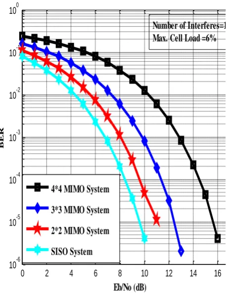
Figure 2 also provides the BER analysis of the various systems in multiple interferers. It was also realized that as the cell range and allowable path loss in decreases the cell load increases dramatically. Interestingly, similar results were obtained in [1] and further observed that base station multiuser detection (MUD) receiver can provide good coverage even with high system load after initial deployment and, finally, concluded that the effect of MUD on cell range depends on propagation environment.
6. CONCLUSION & FUTURE WORK
Analyses of coverage of a loaded and unloaded WCDMA network conducted in this paper revealed that the propagation environment affects the cell range with a given cell loading. Furthermore, for efficient CDMA operation the spectrum must be cleared in a sufficient guard band and guar zone. With cell loading factor of 6% and signal to noise ratio of 10dBthe 4*4 MIMO systems performed better. Besides for a cell load of 50% and a cell range of 1.02km the allowable path loss without MUD was around 98.45dB Also, spectrum monitoring is highly recommended as early as possible in the CDMA system since it is tedious to identify the source of external interference. Intermodulation interference, adjacent and co-channel interference could be considerd in further studies. With path loss with MUD at a cell range of 1.357km was around 110.67dB.
[image:5.595.330.573.70.354.2](41)
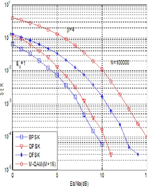
[image:5.595.61.301.307.610.2]Figure 2 Performances of modulation schemes in WCDMA with 18% Cell Load factor with β=6
R
EFERENCES
[1] Vijay Garg, K., 2002 “Wireless Networks Evolution 2G&3G” Prentice Hall PTR, New Jersey
[2] Theodore Rappaport, S., 2002 “Wireless Education, Communications” Second Edition, Pearson Inc, New Jersey
[3] Heiska, K., Posti, H., Muszynski, P., Aikio, P., Numminen, J., Hamalainen, M. 2002 “Capacity Reduction Of WCDMA Downlink in the Presence of Interference from Adjacent Narrow-Band System”
Vehicular
Technology,
IEEE
Transactions,
vol. 51, pp. 37[4] Pei Li, 2006 “The Interference Performances when WCDMA and HSDPA Coexist”,
Information and
Communication Technologies, IEEE,
vol. 2, pp. 2450, Damascus.[5] Joyce, R.M., Graves, B.D., Osborne, I.J., Griparis, T., Conroy, G.R. 2003 “An investigation of WCDMA inter-operator adjacent channel interference”,
3G Mobile Communication
Technologies, 4th International Conference
, IEEE, pp. 149, 25-27[6] Gao Peng, Tu Guofang, Fang Yuan,Liang Shuangchun 2009. “The analysis of the interference
between WCDMA and WIMAX systems”,
Communications
Technology
and
Applications, ICCTA '09. IEEE International
Conference
, pp. 180, Beijing,[7] Schuh, R.E., Andersson, R., Stranne, A., Sommer, M., Karlsson, P. 2003 “Interference analysis for dedicated indoor WCDMA systems”,
Vehicular
Technology Conference, IEEE
, vol.2, pp. 992, 6-9 O[8] Kiiskila, K., Hooli, K., Ylioinas, J., Juntti, M., 2005 “Interference resistant receivers for WCDMA MIMO downlink”,
Vehicular
Technology
Conference, VTC 2005-spring
, IEEE, vol. 2, pp. 836[9] Iskra, S., Thomas, B.W., McKenzie, R., Rowley, J. 2007 “Potential GPRS 900/180-MHz and WCDMA 1900-MHz Interference to Medical Devices”,
Biomedical
Engineering,
IEEE
Transactions, vol. 54,
issues 10, pp. 1858[10]Fuyong Xu, Guangqiu Li, 2005 “Performance analysis of MQAM for MIMO WCDMA systems in fading channels”,
Communications, Circuits
and Systems International Conference IEEE,
vol. 1, pp. 207
[11]Sergio, V. “Multiuser Detection” The Press Syndicate of the University of Cambridge, Pit Building Trumpington Street, Cambridge, CB2, 1RP, United Kingdom.
[12]Ojanpera, T., and Prasad, R., 1998. “Widband CDMA for Third Generation Mobile Communication” Artech House, Boston,
[13]Foerster J. “Channel modeling sub-committee report final”, IEEE 802.15-02/490 (see http://ieee802.org/15/)
[14]Ampoma, E.K.
A
., Rao, T.R. Labay, V.A
., 2009 “Capacity & performance issues in a MIMO based MB-OFDM ultrawide band communication system”,Adaptive Science & Technology, 2nd
International Conference, IEEE
, pp. 432, Accra [15]Liu, H., Qiu, R. C., Tian, Z., 2005 “Errorperformance of pulse-based ultra wideband MIMO systems over indoor wireless channels,” IEEE Wireless Communication conference. vol.4, pp. 2939–2944
[16]Proakis G. “Digital Communication, 2000” Fourth Edition, Irwin/McGraw-Hill, an imprint of the Mcgraw-Hill Companies, Inc, New York, USA,
0 2 4 6 8 10 12 14 16 18
10-6 10-5 10-4 10-3 10-2 10-1 100
BER