5
X
October 2017
Fabrication of Electrical Steering Mechanism
V.Mallikarjuna1, Dr.B.James Prasad Rao2
1,2
Mechanical Department, Annamacharya Institute of Technology & Science, Rajampet A.P. – INDIA -Brilliant Institute Of Engineering & Technology, RangareddyAbdullapur (v),hayathnagar (m),r.r.dist.,hyderabad-501505. City,
Abstract: in an automobiles the advanced requirements ’ has been developing in a vehicle day by day such as dynamics control, comfort, safety etc. The total control of the vehicle will be based on the steering system. Now present days the vehicles are having the comfort steering system i.e., power steering in this present paper are discussing about the advanced steering system i.e., electrical steering system. Based on these requirements’ the new functions are realized by various additional electrical components for measuring the signal processing and actuator control. The realization of the safety driving requires both experience and expertise in design and mass production of electrical steering systems relevant to power steering systems. Beside system safety and system availability the redundant electrical systems also have to meet economic and market requirements. We discussed below full steer-by wire system Full steer-by-wire system
This paper presents solutions for these systems and discusses the various advantages and disadvantages, and comparing of the three steering systems (manual steering, power steering, electrical steering) respectively. Furthermore strategies for failure detection, failure localization and failure treatment are presented. Finally the various specifications for the components used are discussed.
Key words: power steering, safety driving, electrical steering
I. INTRODUCTION
Steering system: It is the system which provides directional change in the performance of an automobile. This system converts rotary movement of the steering wheel into angular movement of the front wheels. It multiplies driver’s effort by mechanical advantage, enabling him to turn the wheels easily.
A. Steering system requirements and functions
For proper and smooth operation and performance of the system, the steering system of any vehicle should fulfill the following requirements:
1) It should multiply the turning effort applied on the steering wheel by the driver.
2) It should be to a certain extent irreversible. In other words, the shocks of the road surface encountered by the wheels should not be transmitted to the driver’s hands.
3) The mechanism should have self rightening effect i.e., when the driver releases the steering wheel after negotiating the turn, the wheel should try to achieve straight ahead position. Types of steering system:
B. Steering system is of the following types
1) Fifth wheel steering system
[image:2.612.223.389.572.672.2]2) Side pivot steering system.
Fig 1.1 fifth wheel steering system
wheel acts as a turntable. The axle assembly is connected with the frame by means of a pin which serves as a pivot around which the axle assembly moves. The fifth wheel contains a ring gear mounted at its rim and is moved by means of a steering. Movement of the steering wheel tends the front axle and wheel assembly to move away.
C. SIDE PIVOT STEERING MECHANISM:
There are two types of steering gear mechanisms:
1) Davis steering gear mechanism
2) Ackermann steering gear mechanism
The main difference between the two steering gear mechanisms is that the Davis steering has sliding pairs, whereas the Ackermann steering has only turning pairs. The sliding pair has more friction than the turning pair; therefore the Davis steering gear will wear out earlier and become inaccurate after certain time. The Ackermann steering gear is not mathematically accurate except in three positions, contrary to the Davis steering gear which is mathematically correct in all positions. However, the Ackermann steering gear is preferred to the Davis steering gear
Fig1.2 Ackermann steering system
D. Ackermann Steering Gear
The Ackermann steering gear mechanism consists of a cross link KL connected to the short axles AC and BD of the two front wheels through the short arms AK and BL, forming bell crank levers CAK and DBL respectively. When the vehicle is running straight, the cross link KL is parallel to AB, the short arm AK and BL both make angle α to the horizontal axis of chassis. In order to satisfy the fundamental equation for correct steering, the links AK and KL are suitably proportioned and angle α is suitably selected.
For correct steering
Fig 1.3 Straight drive
Fig 1.5 Components of steering system
II. STEERING WHEEL
Steering is effected by the steering wheel. The steering wheels of commercial vehicles have a metal armature comprised of a screw machined hub with metal spokes and rim. The hub, spokes and rim are all fabricated into one piece by welding. The armature serves as the load bearing structure of the wheel. The armature is surrounded by a molded rubber or plastic material. Rubber wheels are painted, and plastic wheels utilize impregnated colors.
The steering wheel is of large diameter. This helps to convert the available driver rim pull into maximum input torque. However, the size of the wheel is limited by the following: (1) The comfort of the driver when using the steering wheel. (2) The space available for the steering in the interior of the cabin. (3) The ease of performing maneuvers requiring more than an eighth of a turn of the steering wheel.
The diameter of the steering wheel lies between 42 and 45 cm the case of motor cars, whereas it is 50 to 55 cm in the case of commercial vehicles.
The rim of the steering wheel is elliptical in cross section with the finger indentations on the undersurface. The section of the rim is so designed and dimensioned to provide the driver a good grip both with and without heavy gloves.
A. Manual steering system
Fig 1.6 manual steering components
Manual steering is a system in which manual force is used for steering. Mechanism manual steering rack uses a rack and pinion, worm and roller and recirculation ball and andnut. it is comaparetevly slow and resistance to wheel moment is more .
Elements; steering wheel and column a manual gear box and pit man arm or a rick and pinion assembley,linkages steering knuckles and ball joints and the wheel spindle assemblies.
1) Advantages of manual steering:Mechanical connection between the steering wheel and the wheel and the components continues to be mintedwithout the help of auxiliary power and preferred incomponents continues to be maintainedwithout the help of the auxiliary power and preferred in race cars
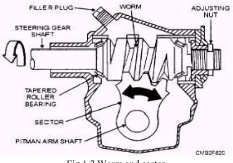
2) Manual Steering Systems :Manual steering is considered to be entirely adequate for smatter vehicles. It is tight. fast, and accurate in maintaining steering control. However, larger and heavier engines.greater front overhang on larger vehicles, and a trend toward wide tread tires have increased the steering effort required. Steering mechanisms with higher gear ratios were tried, but dependable power steering systems were found to be the answer. There are several different types of manual steering 3) Worm and sector :In the worm and sector steering gear (fig. 8-20), the pitman arm shaft carries the sector gear that meshes with
the worm gear on the steering gear shaft. Only a sector of gear is used because it turns through an arc of approximately 70 degrees. The steering wheel turns the worm on the lower end of the steering gear shaft, which rotates the sector and the pitman arm through the use of the shaft. The worm is assembled between tapered rotter bearings that take up the thrust and toad.
Fig 1.7 Worm and sector
B. Worm and Roller
[image:6.612.189.424.477.642.2]worm, which tapers from both ends to the center, affords better contact between the worm and roller in all positions. This design provides a variable steering ratio to permit faster and more efficient steering.
Fig 1.8 Worm and roller
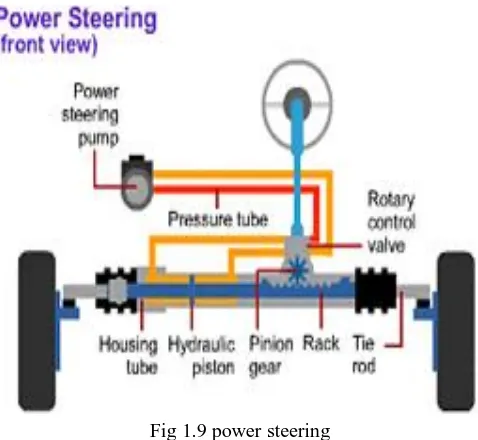
[image:7.612.186.425.350.570.2]C. Power steering:
Fig 1.9 power steering
Power steering is a system that helps in steering the wheels by using power of engine. manual steering is a system in which manual force is used for steering. Steering refers to the mechanism of guiding g the wheels towards the intended direction you must be filmier with the steering. Systems of car. The drivers uses the steering to control the course taken by wheels .power steering is a system that helps in steering the wheel by using power of engine however today most of the cars are using power steering system. Mechanism: hydraulic rack and pinion, recirculation ball and nut, worm and roller hydrostatic electrical rack and pinion, column driven esp., pinion drives esp., rack drives esp. Resistance to wheel moment is less.
Elements: a hydraulic pump, fluid reservoir, hoses lines; and either a power assist unit mounted and a power steering gear assembly
III. ELECTRICAL POWER STEERING
hydraulics also does away with fluid leaks and the need to check the power steering fluid. Electric power steering is also quieter than hydraulic systems because there is no pump noise and no fluid flowing through hoses and valves. But the most noticeable difference is in handling and steering refinement.
Electric power steering can be fine tuned with a precision that is hard to match with hydraulic controls. By monitoring the driver's steering inputs, vehicle speed, and other suspension dynamics, the system can provide just the right amount of steering feel and effort to match rapidly changing driving conditions. EPS can deliver extra effort when you need it, and reduce steering effort when you do not need it. It can even provide steering assist when the engine is off.
[image:8.612.185.425.233.388.2]EPS systems have variable power assist, which provides more assistance at lower vehicle speeds and less assistance at higher speeds. They do not require any significant power to operate when no steering assistance is required. For this reason, they are more energy efficient than hydraulic systems.
Fig 3.1 electrical power steering
A. How Electric Power Steering Works
Though some of the older electric power steering systems were actually "electro-hydraulic," and used an electric motor to drive a conventional hydraulic pump, the latest generation of EPS is all electric/electronic. The steering gear itself is a manual rack with an electric motor mounted on the steering column or the rack.
Fig 3.2 working of electrical power steering
B. Chevy Cobalt Electric Power Steering Modes
The General Motors EPS system has several modes of operation:
1) Normal mode -- Left and right assist is provided in response to inputs and vehicle speed.
2) Return mode -- Used to assist steering return after completing a turn. Feedback from the steering position sensor prevents the EPS system from "overshooting" the center position.
[image:8.612.167.438.482.619.2]4) Protection mode -- Protects electrical components from thermal damage and excessive current flow if the steering is held all the way to one side in the lock position too long.
Turning the steering wheel all the way to one side will cause the Power Steering Control Module (PSCM) to command the maximum amount of current to the EPS motor. If the steering wheel is then held in this position for an extended period of time, the system will go into protection mode so the motor doesn't overheat. In this mode, the PSCM will limit the amount of current to the motor and reduce the level of power assist.
5) Steer-by-wire system;The main feature of future steering systems is the missing direct mechanical link between steering wheel and steered wheels. With such a steer-by-wire steering system Fig. 3.1 the missing steering column’s function must be reproduced in both directions of action. In forward direction the angle set by the driver at the steering wheel is measured by a steering angle sensor and transferred with the suitable steering ratio to the wheels. In reverse direction the steering torque occurring at the wheels is picked up via a torque sensor and attenuated respectively, modified fed back to the driver as a counter torque on the steering wheel.
Fig 3.3 Principle illustration steer-by-wire
First, steering wheel module and steering module are implemented with familiar components of mechanical and electrical steering systems, like: Steering wheel, gearbox, electrical motors, rack. The operational principle is, however, in principle open for more futuristic designs like side stick operation on the driver’s side and single wheel steering on the wheel side. While in systems with mechanical connection in the case of electrical errors only the steering boost is concerned, corresponding measures must be taken with steer-by wire systems that in case of any electrical failure steering control is always guaranteed.
C. Dc Motors
Almost every mechanical movement that we see around us is accomplished by an electric motor. Electric machines are a means of converting energy. Motors take electrical energy and produce mechanical energy. Electric motors are used to power hundreds of devices we use in everyday life. Motors come in various sizes. Huge motors that can take loads of 1000’s of Horsepower are typically used in the industry. Some examples of large motor applications include elevators, electric trains, hoists, and heavy metal rolling mills. Examples of small motor applications include motors used in automobiles, robots, hand power tools and food blenders. Micro-machines are electric machines with parts the size of red blood cells, and find many applications in medicine.
Electric motors are broadly classified into two different categories: DC (Direct Current) and AC (Alternating Current). Within these categories are numerous types, each offering unique abilities that suit them well for specific applications. In most cases, regardless of type, electric motors consist of a stator (stationary field) and a rotor (the rotating field or armature) and operate through the interaction of magnetic flux and electric current to produce rotational speed and torque. DC motors are distinguished by their ability to operate from direct current.
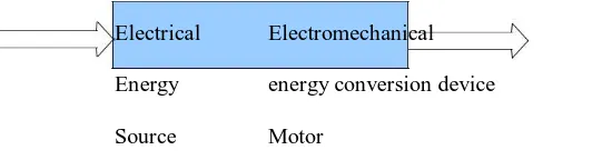
D. Electromechanical Energy Conversion
E. Electric Motor
The input is electrical energy (from the supply source), and the output is mechanical energy (to the load).
Electrical Electromechanical Mechanical
Energy energy conversion device energy
Source Motor Load
F. Electric Generator
The Input is mechanical energy (from the prime mover), and the output is electrical energy.
Mechanical Electromechanical Electrical
Energy energy conversion device energy
[image:10.612.97.372.127.199.2]Source Generator Load
Figure. 2
G. Construction
DC motors consist of one set of coils, called armature winding, inside another set of coils or a set of permanent magnets, called the stator. Applying a voltage to the coils produces a torque in the armature, resulting in motion.
H. Stator
The stator is the stationary outside part of a motor. The stator of a permanent magnet dc motor is composed of two or more permanent magnet pole pieces. The magnetic field can alternatively be created by an electromagnet. In this case, a DC coil (field winding) is wound around a magnetic material that forms part of the stator.
I. Rotor
The rotor is the inner part which rotates.
The rotor is composed of windings (called armature windings) which are connected to the external circuit through a mechanical commentator.
Both stator and rotor are made of ferromagnetic materials. The two are separated by air-gap.
J. Winding
A winding is made up of series or parallel connection of coils.
Armature winding - The winding through which the voltage is applied or induced.Field winding - The winding through which a current is passed to produce flux (for the electromagnet) Windings are usually made of copper.
K. Energy Conversion
L. Value of Mechanical Force
There are two conditions which are necessary to produce a force on the conductor. The conductor must be carrying current, and must be within a magnetic field. When these two conditions exist, a force will be applied to the conductor, which will attempt to move the conductor in a direction perpendicular to the magnetic field. This is the basic theory by which all DC motors operate. The force exerted upon the conductor can be expressed as follows.
F = B i l Newton (1)
where B is the density of the magnetic field, l is the length of conductor, and i the value of current flowing in the conductor. The direction of motion can be found using Fleming’s Left Hand Rule.
Figure 3: Fleming’s Left Hand Rule
The first finger points in the direction of the magnetic field (first - field), which goes from the North pole to the South pole. The second finger points in the direction of the current in the wire (second - current) . The thumb then points in the direction the wire is thrust or pushed while in the magnetic field (thumb - torque or thrust).
M. Principle of operation
[image:11.612.182.397.423.628.2]Consider a coil in a magnetic field of flux density B (figure 4). When the two ends of the coil are connected across a DC voltage source, current I flows through it. A force is exerted on the coil as a result of the interaction of magnetic field and electric current. The force on the two sides of the coil is such that the coil starts to move in the direction of force.
Fig 4.1 principal of operation
Fig 4.2: Induced voltage in the armature winding of DC motor
The value of current flowing through the armature is dependent upon the difference between the applied voltage and this counter-voltage. The current due to this counter-voltage tends to oppose the very cause for its production according to Lenz’s law. It results in the rotor slowing down. Eventually, the rotor slows justenough so that the force created by the magnetic field (F = Bill) equals the load force applied on the shaft. Then the system moves at constant velocity.
N. Torque Developed
The equation for torque developed in a DC motor can be derived as follows. The force on one coil of wire F=il x B Newton
Note that l and B are vector quantities Since B = /A where A is the area of the coil,
Therefore the torque for a multi turn coil with an armature current of Ia:
T = K Ia (2)
Where is the flux/pole in weber, K is a constant depending on coil geometry, and Ia is the current flowing in the armature
winding.
Note: Torque T is a function of force and the distance, equation (2) lumps all the constant parameters (eg. length, area and distance) in constant K.
The mechanical power generated is the product of the machine torque and the mechanical speed of rotation, m Or, Pm=mT
= mK Ia (3)
It is interesting to note that the same DC machine can be used either as a motor or as a
generator, by reversing the terminal connections.
O. Induced Counter-voltage (Back emf):
Due to the rotation of this coil in the magnetic field, the flux linked with it changes at different positions, which causes an emf to be induced (refer to figure 5).
The induced emf in a single coil, e = d c /dt
Since the flux linking the coil, c = Sint
Induced voltage:e = Cos
P. DC Machine Classification
DC Machines can be classified according to the electrical connections of the armature winding and the field windings. The different ways in which these windings are connected lead to machines operating with different characteristics. The field winding can be either self-excited or separately-excited, that is, the terminals of the winding can be connected across the input voltage terminals or fed from a separate voltage source (as in the previous section). Further, in self-excited motors, the field winding can be connected either in series or in parallel with the armature winding. These different types of connections give rise to very different types of machines, as we will study in this section.
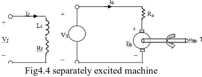
Q. Separately excited machines
[image:13.612.212.420.326.406.2]The armature and field winding are electrically separate from each other. The field winding is excited by a separate DC source.
Fig4.4 separately excited machine
The voltage and power equations for this machine are same as those derived in the previous section. Note that the total input power = VfIf+ VTIa
R. Shunt machine
The armature and field winding are connected in parallel. The armature voltage and field voltage are the same.
Fig 4.5 shunt machine
Notice that in this type of motor,
Total current drawn from the supply, IL= If+ Ia
[image:13.612.217.377.511.645.2]IV. COMPONENTS OF ELECTRICAL STEERING
System overview
A. Functional Description
In an electrical power steering system the steering torque initiated by the driver Fig. 4.1 is measured by a steering wheel torque sensor and is fed into an electronic control unit. The latter then calculates along with the driving speed a reference torque for the steering motor, which, however, can optionally also depend on the steering angle and steering angle velocity. By means of the calculated reference torque the currents of the steering motor are actuated. Fig. 4.1 shows the pinion-type realization, where at the pinion the electrical torque is superimposed to the torque initiated by the driver. In further versions both torques can be superimposed either on the steering column or on the rack. In case of a failing electrical component of this steering system the non-boosted mechanical intervention by the driver is maintained.
B. System Structure Of Steer-By-Wire System With Hydraulic Backupfunctional Description
Figure 4.9 System structure of Electric Power Steering
Figure 4.10 System structure of steer-by-wire system with hydraulic backup
actuator can be operated by means of the steering wheel. Without electric current, the switching valve must be closed. In case of failure of the 42V vehicle electrical system thus the hydraulic bypass is automatically closed and the backup safely activated. If the steering wheel motor can still be controlled during backup operation it can be adequately actuated to support power steering. The increased pressure needed to operate the hydraulic backup is provided by means of a small pressure reservoir with check valve. This pressure accumulator compensates the leakage, which occurs during the vehicle lifetime. The pressure within the backup level is continuously monitored by a pressure or displacement sensor.
C. System Structure Of The Purely Electrical Steer-By-Wire Systemfunctional Description
[image:15.612.143.469.288.531.2]Figure 4.11 System structure of purely electrical steer-by-wire system
Containing additional elements for the diagnosis of charge condition, as well as for the disconnection of batteries.
The steering wheel motor and sensors indicating steering wheel angle and steering wheel torque are arranged at the steering wheel. These components identify the driver’s desire and reproduce the return forces transferred to the steering wheel. For a safe acquisition of steering wheel position two redundant steering angle sensors are used. Power stage and power supply for the steering wheel motor are likewise redundant. In order to exert a return force on the steering wheel in case of a defective steering motor a torsion spring is available to generate the return torque. Optionally a second steering wheel motor can be used in order to redundantly generate the return torque. On the vehicle wheel level the system is equipped with a redundant set of electric motors and redundant sensors measuring angles and torques.
D. Proposed models
Fabrication of electrical steering mechanism
V. CONCLUSION
This paper presents various types of electrical steering systems and their safety aspects. An electric motor is used, yielding energy savings and flexibility of installation. Electrical power steering pursues this trend and offers additional advantages since no hydraulic system is required. A purely electrical system was discussed. Future innovative steering functions, such as vehicle dynamic interventions, collision avoidance, individual wheel steering, tracking assistance, automatic lateral guidance, and finally autonomous driving functions will be implemented in a system compound of various vehicle systems. Future steering systems will thus have to be integrated into a system compound, in terms of interfaces and functions. The steer-by-wire principle becomes absolutely necessary when those innovative functions are to be achieved. The transition to purely electrical steering systems will proceed step by step, for safety reasons and acceptance by the customer. The path will lead from electrical power steering via a steer-by-wire system with a mechanical backup towards purely electrical steer-by-wire systems.
REFERENCES
[1] Branneby, P.; Palmgren, B.; Isakson, A.; Patterson, T.; Frozen, S. (SAAB): “Improved Active and Passive Safety by Using Active Lateral Dynamic Control
and an Unc
[2] onventional Steering Unit“. 13th Int. Technical Conference on Experimental Safety Vehicles, Paris, 2000, pp. 224-230.Daimler-Chrysler: Forschung und
Technologie: Steer-by-wire, NeuartigeAssistenzsysteme, MobilerArbeitsplatz,
[3] Internet site http:// www.daimlerchrysler .de/investor/annual98/ fue1_g.htm 3/99