Technology (IJRASET)
A Review on Generator Grid Synchronization
Needs Effects, Parameters and Various Methods
Ruturaj V. Shinde1, Prof.P.D.Bharadwaj2 1
PG Student , Electrical Power System, 2Assoc. Prof. , Department of Electrical Eng , Bharti Vidhyapeeth Deemed University College of Engineering, Pune, Maharashtra, India
Abstract - Today, microprocessor and microcontroller based devices are preferred for improving reliability and efficiency of manual and automatic synchronizing systems. Synchronization is important in overall power sharing process that it ensures quality, reliability and efficiency within the power system. Synchronization is basically all about matching Voltage, Frequency and Phase angle of both generating unit and respective connected grid. This paper deliberates about need, effect and different technology used for synchronizing generators to grid. Whenever requirement of electric power raises, extra power sources or generators have to connect to respective grid. For more than one generator connected to grid, there are different techniques of synchronization which include manual and automatic operation of synchronization.
Keywords: Synchronizing grid, generator, grid stability, synchronisation
I. INTRODUCTION
Today’s power grid is a huge and complex electrical network as human requires big demand of electrical energy for different purpose. So to fulfill huge power requirement, power grids are forms. In power grid different types of generating sources and load centers are connected to balance the power need at various locations. Synchronizing a generator or alternator to the ac network is very important task and should be done carefully. To connect additional generator to ac grid network, voltage magnitude and frequency of machine have to match with respective grid and phase angle of both generator and grid should be matched while connecting. In Electrical power system synchronizing failure may introduces:
Synchronization failure may affect system stability by producing voltage deviation, transients and unnecessary oscillations within network which disturbs power system stability and reduces overall efficiency of system.
Mechanical strains due to sudden speeding up and speeding down, may harm respective generator and the prime mover.
High currents flow through system which can damage the windings of power transformer and respective generator permanently. Generator may get disconnected from taking load and system gets affected by unbalanced parameters.
Due to increasing abnormalities within system total black out May occurs which shut down all power system. So, it is very important that all generators connected to power grid should proper synchronized with grid parameters.
Generally, design control systems consist of generator synchronizing panel. The synchronizing panel is designed such a way that it shows frequency, voltage magnitude, phase angle, slip so that operator should take necessary action to adjust governor system and excitation system parameters and after matching voltage, frequency and phase angle parameters, closes the synchronizing breakers. This process is generally made by using automatic synchronizing system and additional stand by manual system as backup system. Today, synchronizing methods developed by using various electronic components which give reliable and efficient operation of synchronizing. Using electronic component like microprocessor and microcontroller devices automated and manual synchronizing process can improve considerably. By using advance communication media like fibre optic cables, Input output units can connect to automatic synchronizing system which is located at control room. This reduces various errors occurs during synchronizing and eliminates long voltage transformer circuits runs. Computer based synchronizing system further provides addition information to operator every time, whenever generator connects with grid. This system consist computer controlled soft syncroscope which makes synchronizing more reliable and effective. We will see basic synchronizing techniques and then automatic synchronizing systems.
II. OBJECTIVES
Study the basic concept of Synchronization in Electrical power System. To study effects of poor synchronization on power system.
Technology (IJRASET)
A. Phase SequenceB. Voltage Magnitude
C. Frequency
D. Phase Angle
To study condition for proper synchronization. To study different method of synchronization.
A. Three Dark Lamp Technique
B. Two Bright, One Dark Lamp Technique
C. The Synchroscope Technique
To study demerits of synchronization using lamps method.
To study manual and automatic synchronization concepts.
To take guidelines from these study to develop advanced synchronization technique for Electrical power system.
III.SYNCHRONIZINGPARAMETERS
For proper synchronization of generator and ac power grid, basically four parameters have to consider: Sequence of phases of generator and grid.
Voltage Magnitude of both. Frequency level.
Phase Angle of each phase.
A. Phase Sequence
It is important that, the three phases of both generator and ac network grid should be in same sequence for proper synchronizing.
Generator alternator has three 120ͦ degree apart phases which can be delta or star connected. This phase sequence should be
perfectly matched with grid phase sequence for correct synchronization.
B. Voltage Magnitude
Every generator is designed to give specific output voltage magnitude. While synchronizing generator to respective grid, voltage level should satisfy essential condition in which the voltage magnitude (sinusoidal) generated by must be equivalent to the magnitude of the grid voltage.
C. Frequency
Generator produces electrical energy at certain specific frequency designed by manufacturer as per requirement. The generator frequency should be equal to the frequency on which grid operating. Frequency matching is very important in order to reduce post synchronization transients on overall system. Generally Syncroscope is used to consider frequency parameter.
D. Phase Angle
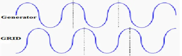
Similar to phase sequence, the phase angle also very important parameter of generator synchronization to grid. Phase angle is an angle between the voltage generated by the generator and the voltage of grid. This phase angle difference must be zero while synchronizing a generator to grid. From observation of peaks and zero crossing incidence of the sinusoidal waveform (i.e. 0 to 360°), the phase angle can be measured.
IV.SYNCHRONIZINGCONDITIONS
For proper synchronizing operation to connecting a generator to existing power grid, following conditions must be satisfied: Sequence of Phase should be same.
Technology (IJRASET)
Figure 1 – Generator and Grid Synchronization.
A. The Phase Sequence
The sequence of three phases or rotation of the three phases of generator which be connected in star or delta configuration must be the same as three phases of the electrical system i.e. ac grid network is to be synchronized. There are only two possible sources of in sequence. During maintenance the generator or transformer terminals might be interchanged or the voltage transformer leads can be interchanged.
B. Voltage Magnitude
The voltage magnitude grid should be equal to the generator voltage magnitude. If the two voltages are not the same and all other conditions are met even though, synchronization may fail. Big MVAR flow causes, if there is a difference between generator and grid voltage magnitude. If the grid voltage is less than the generator voltage still it linked to the ac grid then generator gets overexcited and it flows more MVAR though system. If there is voltage difference such that, the grid voltage magnitude is more than the generator voltage magnitude and if under this condition, generator connected with grid then the generator will behaves under-excited so it will take up more MVAR from system.
C. Frequency
[image:4.612.161.455.419.519.2]The generator frequency and voltage frequency ac grid network should be same for proper synchronization.
Figure.2 Generator slower than grid.
The syncroscope rotates rapidly counter clockwise. In case of breaker of the generator accidently closed it will cause the generator out of step with the ac grid system is to be connected. After this situation generator will acts as motor and grid tries to take it up to speed. Due this, it will harm the generator because slipping of stator and rotor poles occurs. If generator were faster than the grid then similar problem will observed with system.
[image:4.612.157.459.601.695.2]Technology (IJRASET)
The generator and grid are matching speed is shown in figure 3.At same speed rate zero crossing and peak point of voltage sine wave occurs. In figure 2 it appears as a non-rotating syncroscope because phase angle and the grid exist among them. At this instance, if a generator breaker gets closed, the grid system will pull generator into step. Under this situation stress on stator and rotor will increases, with high inrush current flow through generator. Due to this generator may damage permanently. With same forces, a leading generator will try to take power into grid network instantly. So it is very essential to match exactly waveform of generator and grid.
V. SYNCHRONIZINGTECHNIQUES
A. Conventional Techniques
There are various techniques that are used for generator or alternator synchronization, here explained various schemes to connect the generators to the grid. Following are synchronization schemes:
Three Dark techniques
Two Bright, One Dark technique The Synchroscope technique
These techniques are most preferred in old days but due to manual operation and less accuracy this technique needs a very skilled individual also these methods have less reliability and security. So, now days generally Synchroscope technique and microprocessor or microcontroller device based synchronizing systems are more used for the automatic synchronization operation of the generators. Because using microcontroller base systems generator synchronization becomes much more reliable and easier to operate than conventional methods.
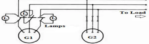
1) The Dark Lamp Method: The three-dark method for synchronize two three-phase generators. Generator-2 is connected to the load circuit. Generator-1 is to be connected in parallel with generator-2.Three bulbs or lamps are connected between generator Generator-2 and the load with double the output voltage to the load as shown in figure 4. Following effects are observed when two generators operate:
Depend on the difference of two generators frequency rate the three lamps will glow and go out together.
If the Generators are not linked in the correct phase order and out of phase. Then depend on the difference of two generators frequency rate the three lamps will glow and go out but not in unison. For proper phase sequence it is needed to exchange any two leads to generator G1. Until all lamps glows and go out in unison, the generators are not paralleled. The lamp technique has better simplicity of process.
By slightly adjusting the speed of generator-1, generators frequency can be equalized. This will glow synchronizing lamps and go out with lowest rate. After out the three lamps, at this point, instantaneous electrical polarity is same of the 1 as generator-2. Now voltage magnitude of generator-1 is same as generator-2 and also in phase with each other. At this point synchronizing switch can be closed to supply power from both generators to grid connected loads. so that both generators can provide the supply to grid connected loads. This can be considered as two generators are in synchronism with grid system as per three lamps dark technique.
[image:5.612.162.450.574.659.2]Even though this method is simple and cost effective, it has some demerits. Across lamp it may have high voltage, even though it is dark burned out. Due to this it may possible that paralleling connection may switch, even there is large difference between generators voltage and phase.
Figure 4 Synchronization of generators by 3 dark lamps method
Technology (IJRASET)
lamps connections is shown in figure 5 B. In this method, if lamp-1, lamp-2 becomes bright and lamp-3 becomes dark then generators get synchronized. The synchronizing instant is when out of three lamps one lamp is blowing dim and other two are brighter. At this exact instant synchronizing switch can be closed. So it is very easy to operator to decide when to close the synchronizing switch by observing the sequence of synchronizing lamps light. For knowing the speed of generator (i.e. too slow or too fast) which is to be synchronized is decided by observing the sequence of bright lamps.
Figure.5 (A) The Three-Dark Technique; (B) Two-Bright, One-Dark Technique
a) Demerits Of Synchronization System Using Lamps' Method Are
i. Operator should be very skilled for giving correct judgment of Synchronization instants by using incandescent lamps.
ii. By using this technique it is not possible to know i.e. generator is slow or fast.
iii. For high voltage generators, extra apparatus like step down transformers needed for lamps, because lamps are generally of low ratings.
3) The Synchroscope Method: For knowing exact instant to closing synchronizing switch a syncroscope device is used. A pointer rotates on the dial in syncroscope. If the generator is running slower then pointer rotation direction will be in anticlockwise and if generator is running faster, then pointer rotation direction will be in clockwise. When the pointer of syncoscope is exact straight upwards it is correct movement of closing the switch of synchronization. As we know in lamps method synchronization effectiveness generally depends on operator experience, decision and skill. The three lamp technique is easy and cost efficient but in this method it cannot provide information about frequency i.e. it is higher or lower for synchronizing generators. So for this purpose syncroscope device used which informs about incoming generators frequency whether it is lower or higher. For big voltage systems, lamp technique cannot be used so generally synchroscope technique is preferred. In its construction it consist one moving vane and three coils. The coils of syncroscope are connected to the generators and bus bar which is to be synchronized and pointer connected to moving vane. The use of voltage transformer for measuring the difference in voltage, the pointer will rotate in clockwise direction or anti clockwise direction and after speed of incoming generators becomes equal the pointer, it will stop at upward vertical direction and relays switched to connect the generator to the grid bus bar. Figure 6 shows below, the pointer move in anti-clockwise or clockwise direction and after incoming generators speed becomes equal to that of bus, relays will be closed for synchronizing.
Figure.6 Synchronization of Alternator Using Synchroscope
The pointer of Synchroscope will continuously in motion if the two voltages phase angle is different. If the incoming generator is slower then it will move to slower point and if then incoming generator is faster then it will move towards the faster point and after equal frequency of generator and grid bus bar pointer will stop moving. This situation is for closing synchronization switch.
Technology (IJRASET)
[image:7.612.195.431.144.255.2]checking proper phase rotation and testing the generator. For determining proper phase rotation Synchronizing lamps may be used. In various applications, the generator connections to the grid through a paralleling switch are permanent. In these case phase rotation checking are not essential. For synchronizing generator to the grid only syncroscope instrument is needed in these cases. For double check system, a set of bulbs can be used for synchronization purpose.
Figure 7 Synchroscope meter and synchronizing indicator
VI.SYNCHRONIZINGMETHODS
Now days followings three most used methods are used for generator synchronizing: Manual synchronizing method
Manual with permissive relay (synch check) synchronizing method Automatic synchronizing method.
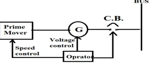
A. Manual Synchronizing
Manual synchronizing method is generally used on a variety of generating stations. In manual synchronizing system basically it includes component like synchronizing lamps or lights, a synchroscope instrument, metering devices and a breaker to close switch at right instant.
In manual synchronizing method operator Controls generators voltage magnitude and speed and operates the relays or breaker at the exact synchronism instant. The main advantages of this system are simplicity and cost effectiveness. Any type of generator can be synchronized by an operator is possible and easy monitoring the power plant is possible in manual method.
Figure.8 Manual synchronizing.
B. Manual with Permissive Relay
[image:7.612.186.446.456.561.2]Technology (IJRASET)
Figure.9 Manual synchronizing with synch check relay
C. Automatic Synchronizing
As name indicates, this synchronization method is an automatic synchronizing process, The automatic synchronizer (ANSI/IEEE Device 25A) is capable to monitor and control frequency, voltage and phase angle, and it also provides improvement in respective signals for voltage matching and frequency matching with grid parameters and after satisfying all conditions it will provides signal to the breaker to close contact at correct instant.
Figure.10 Automatic Synchronizing
VII. AUTOMATICSYNCHRONIZERS
A. Phase Lock Type Automatic Synchronizers
This is one of automatic system for synchronization of generator with grid. The synchronizer which is phase matching type is automated system in which it gives a breaker closing angle window and voltage magnitude approval. In this system if a generator is within specified operation window, the synchronizer system activates a relay and initializes the breaker closing process at correct instant.
The phase lock type synchronizer uses the concept of improving the signals that are useful to operate governor control system and automatic voltage regulation system. These signals are provided by synchronization system until the all synchronizing parameters are perfectly matched with grid parameter. This type of synchronizer can provides respective control signal to governor system to control the speed of generator to match various parameters with grid.
As the control signal controls the prime mover output which controls speed of generator. When the voltage reaches a correct magnitude with respect to grid system it will initialize the synchronizing switch to connect generator to grid. The synchronizer senses frequency, phase angle and bus voltage of both generator and the grid.
Technology (IJRASET)
The synchronizer measures a difference between the generator and grid for voltage, frequency, and phase angle and if any difference found by system it will generate the appropriate signals to correct that difference and to match all parameters with grid. This automatic synchronizing system is designed with the help of using various electronics component like comparator; microprocessor/microcontroller etc.
B. Advantages of Automatic Synchronizer
1) Frequency/Phase Correction Option: Automatic synchronizing system designed with electronic components which will provide comparative values and appropriate corrective signals. For frequency correction bipolar d-c correction output signals provide to the governor until the generator frequency is corrected to within ±3 Hz of the grid bus frequency. After ±3 Hz difference is achieved, the output signal of system is proportional to the frequency difference. Then synchronization system contacts output correction signals and if the phase angle is greater than the setting of front panel then the output contact will closed. The contact will open only after phase angle is less than the setting of front panel setting.
2) Option For Correction Of Voltage : Automatic system provides voltage correction facility. Now day’s generally generating units have automatic voltage control system. By using this concept of AVR it will provide the corrective signals to the system to match voltage magnitude of generator to the grid voltage. Process of the voltage matching selection is same as frequency or phase angle matching, but in this correction signal used to regulate generator voltage magnitude. When the automatic
synchronizer gets in touch with output voltage matching and it will wait until voltage difference of the generator and the grid brings within particular limit the switch contact remains closed.
3) Option Of Dead Bus: The automatic synchronization system has the dead bus option in which it allows the generator to connect to the bus bar even if the bus may very low or inactive. This is very useful characteristic of automatic synchronization system to provide emergency reserve systems that need the first connect generator up to the dead grid bus.
VIII. FUTURETRENDS
By looking at the number of papers published and various article on grid synchronization technologies in recent years, it is easy to conclude that Synchronization of generator study and improvement activities are experiencing an explosive rate of growth. Although this paper has focused on concept of synchronization, need of synchronization, effects of poor synchronization on system, synchronization parameters and conditions and different methods of synchronization, there is other research and development in related areas, such as more reliable and transient less synchronization technique.
IX.CONCLUSION
We have studied need of synchronization in electrical power system, various parameter and conditions of synchronization, different methods of synchronization and the automatic synchronizing process and explored some of the considerations involved. We have tried to establish some guidelines for the selection of the proper synchronizing system for the application.
X. ACKNOWLEDGMENT
I am highly grateful thank to my guided Prof. Prasanna D Bharadwaj for his constant intellectual support in the form of his innovative ideas and valuable guidance. I am also grateful to Dr. D.S. Bankar (Head of the Department) and Asst. Prof.Holmukhe (M.Tech Co-ordinator) for their guidance. We place on record my extreme indebtedness to them for providing us proper guidance at every step.
REFERENCES
[1] Implementation of Parallel Synchronization Method of Generators for Power & Cost Saving in University of Gujrat Uzma Amin, Ghulam Ahmad, Sumbal Zahoor, Fariha Durrani Electrical Engineering Department, Faculty of Engineering, University of South Asia, Lahore, Pakistan Email: [email protected] [2] Synchronization Methods for Three Phase Distributed Power Generation Systems. An Overview and Evaluation Adrian Timbus, Remus Teodorescu and Frede
Blaabjerg Institute of Energy Technology Aalborg University DK-9220 Aalborg, Denmark Email: [email protected], [email protected], [email protected] [3] Design of an Automatic Synchronizing Device for Dual- Electrical Generators Based on CAN Protocol By Ahmad I. Abo Dabowsa
[4] Fundamentals and Advancements in Generator Synchronizing Systems Michael J. Thompson, Schweitzer Engineering Laboratories, Inc.
[5] Phase locked loop and synchronization methods for grid interfaced converters: a review Xiao-Qiang GUO, Wei-Yang WU, He-Rong GU Yanshan University [6] Advances in Generator Control and Automatic Synchronization – Eliminating the Need for Standalone Synchronization Systems Nicholas C. Seeley Schweitzer
Engineering Laboratories, Inc. Cameron Craig Ensco Terry Rainey Chevron USA
Technology (IJRASET)
[8] Turbine Generator Synchronization – Two Case Studies M. Salman Leong , Lim Meng Hee, and Guai Yeu Kae Universiti Teknologi, uala Lumpur, Malaysia [9] A Guidebook on Grid Interconnection and Islanded Operation of Mini-Grid Power Systems Up to 200 kW Chris Greacen Richard Engel Thomas
Quetchenbach.
[10] Overview of Control and Grid Synchronization for Distributed Power Generation Systems Frede Blaabjerg, Fellow, IEEE, Remus Teodorescu, Senior Member, IEEE, Marco Liserre, Member, IEEE, and Adrian V. Timbus, Student Member, IEEE
[11] Synchronization in Electrical Power Network Oren Lee, Thomas Taylor, Tianye Chi, Austin Gubler, Maha Alsairafi [12] Grid Connection David Roberts Hydro Power Consultant [email protected]
[13] Grid Synchronization Technology For Distributed Power Generation System Yonggang Li1*, Jianwen Li1, Yaxiong Lei 1, Wei Sun 2 1. North China Electric Power University, Baoding, Hebei; 2. Baoding Power Supply Company, ebei *[email protected]
[14] Advances in Generator Control and Automatic Synchronization – Eliminating the Need for Standalone Synchronization Systems Nicholas C. Seeley Schweitzer Engineering Laboratories, Inc. Cameron Craig Ensco Terry Rainey Chevron USA