Technology (IJRASET)
Patch Antenna using Metamaterial Structure for
improving parameters on 3.2 layers
At 2.787 GHz
Rahul Yadav1, Prof. Umesh Barahdiya2, Prof Manoj Jakheniya3, Prof. S.S.Dhakad4
Electronics and Communication Engineering, Nagaji Institute of Technology and Management, Gwalior, India
Abstract— In this paper, a novel printed rectangular patch antenna with 3.2 layer, resonant at 2.787 GHz frequency, is proposed. The given antenna is composed of a rectangular patch antenna with retangular structure on 3.2 layers. The antenna is designed for resonating at 2.787 GHz frequency. The return loss of the proposed antenna is -40.762816 dB at 2.787 GHz frequency which is in good agreement. A rectangular vertical strip is also used for minimizing the return loss. The 50 ohm port is used to fed the proposed antenna.
Keywords—patch, return-loss, bandwidth, printed antenna.
I. INTRODUCTION
Antenna has been around for a long time, millions of years, as the organ of touch or feeling of animal, birds and insects. But in the last 100 years they have acquired a new significance as the connection link between a radio system and the outside World. The first radio Antenna was built by Heinrich Hertz, a professor at the Technical Institute in Karlsruhe, Germany. The IEEE standard defines an antenna as a part of a transmitting or receiving system that is designed to radiate or to receive electromagnetic waves [1]. A patch antenna is a low-profile antenna consisting of a metal layer over a dielectric substrate and ground plane. Typically, a patch antenna
is fed by a microstrip transmission line, but other feed lines such as coaxial can be used. [2–3] The advantages of patch antennas are that they radiate with moderately high gain in a direction perpendicular to the substrate and can be fabricated in a low cost FR-4 substrate. Micro-strip antennas have unique features and attractive properties such as low profile, light weight, compactness and Conformability in structure [4]. With those advantages, the antennas can be easily fabricated and integrated in solid-state devices. Micro-strip antennas are widely applied in radio frequency devices with single-ended signal operation. This has recently been used in microwave design with a combination of meta-materials, either as a cover or a substrate [5]. In modern wireless communication systems, the micro-strip patch antennas are commonly used in the wireless devices. Therefore, the miniaturization of the antenna has become an important issue in reducing the volume of entire communication system [6]. V.G. Veselago in 1968 provided a theoretical report on the concept of meta-material (MTM) [7]. The “patch” is a low-profile, low gain, narrow bandwidth antenna [8-10]. Aerodynamic considerations require low profile antenna on aircraft and many kinds of vehicles. Typically a patch consists of
thin conducting sheet about 1 by 1/2 λ0 mounted on Substrate. Radiation from the patch is like radiation from two slots, at the left and right edges of the patch.
II.ANTENNA DESIGN THEORY
Technology (IJRASET)
The RMPA parameters are calculated from the following formulas
A. Calculation of Width (W)
Where C = free space velocity of light,
εr =Dielectric constant of substrate
The effective dielectric constant of the rectangular micro-strip patch antenna:
B. Actual length of the patch (L)
C. The actual length of the Patch (L).
D. Calculation of Length Extension
Technology (IJRASET)
Figure 2: Simulation of return loss and bandwidth of RMPA alone.
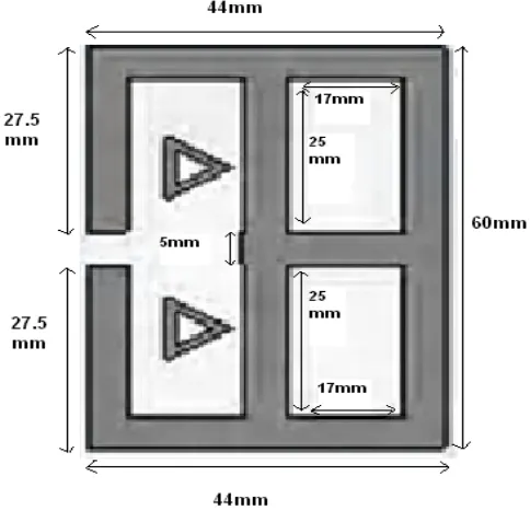
TABLE.I: STRUCTURAL PARAMETERS OF SIMPAL PATCH ANTENNA
Sr. No. Parameters of patch antenna
Parameters Dimension Unit
1. Dielectric constant 4.3 -
2. Loss tangent (tan ) .02 -
3. Thickness (h) 1.6 mm
4. Operating frequency 2.787 GHZ
5. Length L 24.8467 mm
6. Width W 32.162 mm
7. Cut width 5 mm
8. Cut depth 9.1235 mm
9. Path length 21.5467 mm
Technology (IJRASET)
Fig.3 shows the structure of the proposed antenna and the. The antenna is modeled and simulated using method of moment based electromagnetic simulation software CST, version 10, between 0 to 3GHz.
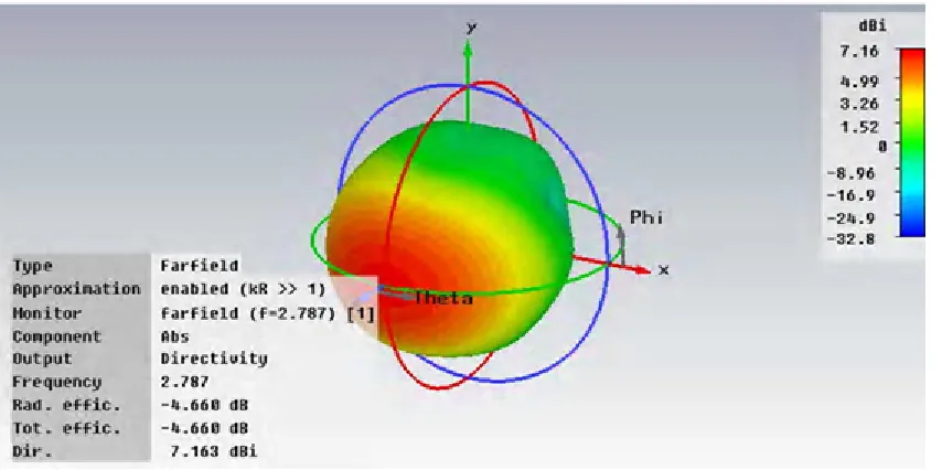
Fig. 2 and 4 shows the graph of return loss V/s frequency, VSWR Vs. frequency and impedance variations V/s. frequency respectively. The graph of return loss shows that antenna is resonating at 2.787GHz frequency with return loss of -40.762816dB and bandwidth of proposed antenna is increased up 33 MHz and directivity is also increased
[image:5.612.174.416.384.617.2]Technology (IJRASET)
[image:6.612.217.401.368.575.2]Figure 6: directivity graph
Figure 7: Smith chart of RMPA loaded with metamaterial
Technology (IJRASET)
IV. CONCLUSION
A printed RMPA antenna at 2.787 GHz frequency is analyzed. The antenna is modeled on low cost and easily available FR4 substrate. The antenna is resonating at 2.787GHZ with return loss -40.762816dB and bandwidth of proposed antenna is increased up 33 MHz and directivity is also increased Using CST-MWS software
REFERENCES
[1] “IEEE standard definitions of terms for antennas," IEEE Std 145-1983, 1983
[2] C.A. Balanis, Antenna Theory and Design, John Wiley & Sons, 1997.
[3] S.N. Burokur, Mo. Latrach, S. Toutain, “Theoritical investigation of a circular patch antenna in the presence of a left-handed mematerial,” IEEE Antennas and Wireless Propagation Letters, Vol. 4, 2005.
[4] C. M. Krowne, “Low loss guide wave propagation in a left-handed microstrip structure using dispersive split ring- rod combination metamaterial,” IET Microw. Antennas Propag ., 1, 887, 2007.
[5] R.W. Ziolkowski, “Double negative metamaterial design, experiments and applications,” IEEE Transactions on Microwave Theory and Tech- niques, vol. 51, no. 7, 2003.
[6] W.L. Stutzman, G.A. Thiele, Antenna Theory and design, John Wiley & Sons, 2nd Ed., New York, 1998.
[7] H.A. Majid, M. Rahim, T. Marsi, “Microstrip Antenna gain enhancement using left-handed metamaterial structure,” Progress in Electromagnetics Research M, Vol. 8, pp. 235–247, 2009.
[8] Veselago, V. G., The electrodynamics of substances with simultaneously negative values of ɛ and µ" Soviet Physics Uspekhi, Vol. 10, No 4, 509-514, 1968. [9] G. Lovat et al , “Combinations of low/high permittivity and/or permeability substrates for highly directive planar metamaterial antennas,” IET Microw.
Antennas Propag. 1, 177, 2007.
[10] Huda A. Mazid et al , “Left-handed metamaterial design for microstrip antenna application”, IEEE International RF and Microwave conference , 2008.
[11] Suh, S.-Y., W. L. Stutzman, and W. A. Davis, A new ultrawideband pinted monopole antenna. The planar inverted cone antenna (PICA)," IEEE Transactions an Antennas and Propagation, Vol. 52, No. 5, 1361{1365, 2004.
[12] Tae-Hyun Kim and Dong-Chul Park, Compact Dual-band Antenna with Double L-Slits for WLAN Operation, IEEE Antennas and Wireless Propagation Letters, Vol.4,2005.
[13] J.B. Pendry, “Negative refraction males a prefect lens,” Phys Rev Lett-85 ,” 2000, pp. 3966–3969.
[14] Bhim Singh., Dr. Rekha Gupta, Neelima Chaudhary, Sapana Yadav, “Rectangular microstrip patch antenna loaded with symmetrically cut H and Hexagonal shaped metamaterial structure for bandwidth improvement at 1.794 GHz” International Journal of Advanced Technology & Engineering Research ,Volume 2, Issue 5, Sept 2012