© 2016, IRJET | Impact Factor value: 4.45 | ISO 9001:2008 Certified Journal
| Page 346
Analysis of Beam Column Joint Subjected to Seismic Lateral Loading
Snehal A. Baitule
1Prof. Hemant B. Dahake
21
M. E (Structure) Scholar, Civil Engineering Department,
G. H. Raisoni College of Engineering and Management, Amravati, Maharashtra, India.
2
Assistant Professor, Civil Engineering Department,
G. H. Raisoni College of Engineering and Management, Amravati, Maharashtra, India.
---***---Abstract -
The beam-column joints are among the weakest members of reinforced concrete frames in terms of seismic resistance. Failure of beam column joints during earthquake is governed by bond and shear failure mechanism which are brittle in nature[8].This study presents critical review of recommendations of well established codes regarding design and detailing aspects of beam column joints This paper presents a review of the postulated theories associated with the behavior of joints under ACI 318M-02 and IS 13920: 1993 Code. Understanding the joint behavior is essential in exercising proper judgments in the design of joints. The paper discusses about the seismic actions on various types of joints and highlights the critical parameters that affect joint performance with special reference to bond and shear transfer.
Key words-
Beam-column joint, shear failure, seismic
action, moment resisting frame.
1. INTRODUCTION
Earthquake is a global phenomenon. Due to frequent occurrence of earthquakes it is no more considered as an act of God rather a scientific happening that needs to be investigated. During earthquake, ground motions occur both horizontally and vertically in random fashions which cause structures to vibrate and induce inertia forces in them. Analysis of damages incurred in moment resisting RC framed structures subjected to past earthquake show that failure may be due to utilization of concrete not having sufficient resistance, soft storey, beam column joint failure for weak reinforcements or improper anchorage, column failure causing storey mechanism3. Beam-column connection is considered to be one of the potentially weaker components when a structure is subjected to seismic loading9.
1.1 REVIEW OF CODE
Some international codes suggest expressions to prevent storey mechanism of collapse due to possible damage
locations (hinge formations) in columns. This actually aims at achieving stronger columns with moment capacities more than those of beams framing into a joint obtained considering over strength factors. Moment Calculation at centre of the joint is a very complicated task. These moments are the design moment of resistance of columns or beams calculated at outer faces of the joint and a suitable allowance for moment obtained because of shear developed at the face of joint. However due to such assumptions, the accuracy decreased is very less and the simplification achieved is considerable if the shear allowance is neglected.
1.2 Theoretical Development of R.C.C Joint
Under earthquake shaking, the beams adjoining a joint are subjected to moment in the same direction (clockwise or anti-clockwise)9. Figure 1 shows the moments created under the earthquake shaking. Because of these moments, the top bars in the beam column joint are pulled out in one direction and bottom bars in the other direction. Figure 1 shows the behaviour of reinforcing bars under earthquake shaking. These forces are balanced by bond stresses developed between concrete and steel in the joint region. If the column is not wide enough or if the strength of concrete in the joint is low; then there will be insufficient grip between concrete and steel bars8. In such circumstances, the bar slips inside the joint region, and beams lose their capacity to carry load.
© 2016, IRJET | Impact Factor value: 4.45 | ISO 9001:2008 Certified Journal
| Page 347
Further, under the action of the above push-pull forces at top and bottom ends, joints undergo geometric distortion. One of the diagonal lengths of the joint elongates and the other compresses. Figure 2 shows the geometric distortion of the joint. If the column cross-section size is insufficient, the concrete in the joint can develop diagonal cracks.
Fig.2 Geometric Distortion of the Joint
The design of Beam-column joint is mainly focused on providing joint shear strength and adequate anchorage within the joint. IS 13920:1993 code of ductile detailing of reinforced concrete structures subjected to seismic forces has given recommendations for the strengthening of the joint6.
2. OBJECTIVE OF STUDY
The scope of present research work is limited to following structural considerations:
Residential G+5 RC framed building is selected.
The analysis is carried out using STAAD-Pro. Software
Seismic analysis is carried out by equivalent static method using IS 1893:2002.
Design of Beam- column Joint by IS 13920:1993, ACI3198-02, EN 1998-1:2003.
Comparison of design parameters.
1.
METHODOLOGY
1. The building considered in the present report is G+5 Residential RC Framed structure. Complete analysis is carried out for dead load, live load & seismic load using STAAD-Pro. All combinations are Considered as per IS 1893:2002.
2. The Structure is designed by IS 13920:1993,ACI 318-05and EN 1998:2004
3. Ultimate flexural capacity of beam (Mr,b) is determined from the design data obtained. 4. Column reinforcement in the buildings is
progressively increased to attain different
5. column to beam moment capacity ratio (MCR) at maximum moment, at zero axial load and at design axial load.
6. Beam column joints in a reinforced concrete moment resisting frame are crucial zones for transfer of loads effectively between the connecting elements (i.e., beams and columns) in the structure and hence shear strength checked and design by Draft provisions in IS 13920:1993,ACI 318-05 and E
N
1 9 9 8 : 2 0 0 4 .
F
Fig.3 Plan of G+ 5 RC Framed Structures
3.1. Building Properties
Site Properties:Details of building:: G+5 Outer wall thickness:: 230mm Inner wall thickness:: 150mm Floor height ::3 m
Depth of foundation :: 1500mm Bearing capacity of Soil:: 150kN/m²
Seismic Properties Seismic zone:: V Zone factor:: 0.36 Importance factor:: 1
Response Reduction factor R:: 5 Soil Type:: medium
Material Properties
Material grades of M30& Fe415 were used for the design. Loading on structure
Dead load :: self-weight of structure Weight of 230mm wall Weight of 115mm wall Live load:: Floor 3kN/m²
© 2016, IRJET | Impact Factor value: 4.45 | ISO 9001:2008 Certified Journal
| Page 348
Preliminary Sizes of membersColumn:: 300mm x 800mm
Transverse Beam:: 230mm x 800mm Longitudinal Beam:: 230mm x 700mm Slab thickness:: 125mm
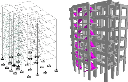
4. MODELING
This building has been modelled as 3D Space frame model with six degree of freedom at each node using STAAD-Pro software for stimulation of behaviour under gravity and seismic loading. The isometric 3D view and plan of the building model is shown as figure. The support condition is considered as fully fixed.
Fig.4 Different 3D View of G+5RC Structure
Fig. 5 Deflected shape of G+5 in X and Z- direction
4. RESULT
4.1 The comparison of column depth in x-dir and z-dir at Exterior, Interior and Corner joints Table 1, 2, 3.
Table .1 Column depth at Exterior Joint in (mm)
Comparison of Column depth at Exterior Joint (mm)
IS 13920 ACI 318-05 EN 1998-01
X - direction 800 800 850
Z - direction 500 350 350
Table . 2 Column depth at Interior Joint in (mm)
Comparison of Column depth at Interior Joint (mm)
IS 13920 ACI 318-05 EN 1998-01
X - direction 850 850 900
Z - direction 350 350 450
Table.3 Column depth at Corner Joint in (mm)
Comparison of Column depth at Corner Joint (mm)
IS 13920 ACI 318-05 EN 1998-01
X - direction 850 850 850
Z - direction 450 420 350
4.1.1 The graphical representation of column depth in x-dir and z-dir at Exterior, Interior and Corner joints are
presented in Figure – (a), (b)
Fig-(a) Comparison of Column depths in (mm) in X -
direction
0 200 400 600
Exterior Joint
Interior Joint
Corner Joint
Comparision of Column depth in
(mm) in Z- direction
IS 13920
ACI 318-05
[image:3.595.50.266.279.417.2] [image:3.595.322.555.403.553.2] [image:3.595.43.257.464.576.2]© 2016, IRJET | Impact Factor value: 4.45 | ISO 9001:2008 Certified Journal
| Page 349
Fig-(b) Comparison of Column depths in (mm) in Z -direction
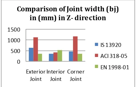
4.2 The comparison of effective joint width in x-dir and z-dir at Exterior, Interior and Corner joints are presented in Table 4, 5, 6
Table. 4 Effective Joint Width at Exterior Joint in (mm)
Table.5 Effective Joint Width at Interior Joint in (mm)
Table.6 Effective Joint Width at Corner Joint in (mm)
Comparison of effective joint width (bj) at Corner Joint (mm)
IS 13920 ACI 318-05 EN 1998-01
X - direction 455 725 475
Z - direction 450 1155 350
5.2.1 The graphical representation of effective joint width in x-dir and z-dir at Exterior, Interior and Corner joints are presented in Figure– (c), (d)
Fig-(c) Comparison of Joint width (bj) in X- direction
Fig- (d) Comparison of Joint widths (bj) in Z- direction
5.3 The comparison of joint shear strength in x-dir and z-dir at Exterior, Interior and Corner joints are presented in Table 7, 8, 9
Table.7 Joint Shear Strength at Exterior Joint in (kN)
Comparison of Shear Strength at Exterior Joint (kN)
IS 13920 ACI 318-05 EN 1998-01
X - direction 3680.696 1352.22 911.786
Z - direction 2070.391 5204.15 1577.75
Table.8 Joint Shear Strength at Interior Joint in (kN)
Comparison of Shear Strength at Interior Joint (kN)
IS 13920 ACI 318-05 EN 1998-01
X - direction 1365.883 2646.41 3022.51
Z - direction 2444.212 1090.16 1763.13
Table.9 Joint Shear Strength at Corner Joint in (kN) Comparison of effective joint width (bj) at Exterior Joint (mm)
IS 13920 ACI 318-05 EN 1998-01
X - direction 700 655 475
Z - direction 630 1105 350
Comparison of effective joint width (bj) at Interior Joint (mm)
IS 13920 ACI 318-05 EN 1998-01
X - direction 475 400 450
Z - direction 350 400 525
Comparison of Shear Strength at Corner Joint (kN)
IS 13920 ACI 318-05 EN 1998-01
X - direction 1121.462 1428.79 966.68
Z - direction 2095.04 4631.23 1577.75 0
200 400 600 800
Exterior Joint
Interior Joint
Corner Joint
Comparison of Joint width (bj)
in (mm) in X- direction
IS 13920
ACI 318-05
EN 1998-01
0 500 1000 1500
Exterior Joint
Interior Joint
Corner Joint
Comparison of Joint width (bj)
in (mm) in Z- direction
IS 13920
ACI 318-05
[image:4.595.315.541.112.254.2]© 2016, IRJET | Impact Factor value: 4.45 | ISO 9001:2008 Certified Journal
| Page 350
5.3.1 The graphical representation of joint shear strenght
in x-dir and z-dir at Exterior, Interior and Corner joints are presented in Figure– (e), (f)
Fig-(e) Comparison of Shear Strength in (kN) in X- direction
Fig-(f ) Comparison of Shear Strength in (kN) in Z- direction
5.4 The comparison of moment capacity ratio in x-dir and z-dir at Exterior, Interior and Corner joints are presented in Table 10,11,12.
Table.10 Moment Capacity Ratio at Exterior Joint
Table.11 Moment Capacity Ratio at Interior Joint
Comparison of Moment Ratio at Interior Joint
IS 13920 ACI 318-05 EN 1998-01
X - direction 1.47 3.89 3.73
Z - direction 3.16 2.77 2.3
Table.12 Moment Capacity Ratio at Corner Joint
Comparison of Moment Ratio at Corner Joint
IS 13920 ACI 318-05 EN 1998-01
X - direction 2.78 6.59 2.36
Z - direction 4.26 4.9 5.03
5.4.1 The graphical representation of moment capacity ratio in x-dir and z-dir at Exterior, Interior and Corner joints are presented in Figure – (g), (h).
Fig- (g) Comparison of Moment ratio in X- direction
Fig- (h) Comparison of Moment ratio in Z- direction Comparison of Moment Ratio at Exterior Joint
IS 13920 ACI 318-05 EN 1998-01
X - direction 4.05 4.17 1.99
Z - direction 1.56 2.13 2.83
0 2 4 6 8
Exterior Joint
Interior Joint
Corner Joint
Comparison of Moment ratio in
X- direction
IS 13920
ACI 318-05
© 2016, IRJET | Impact Factor value: 4.45 | ISO 9001:2008 Certified Journal
| Page 351
5.
SUMMARY AND CONCLUSIONS
The structural behavior will be different from that assumed in the analysis and design, if the joints are incapable of sustaining the forces and deformations induced due to the transfer of forces among the members meeting at the joint. Especially, opening of joints has to be considered properly since it will result in diagonal cracking of the joint. Such opening of joints occurs in multi-storied structures due to lateral loads. The discussions presented pertain to seismic forces, but are of general nature and can be applied to structures subjected to lateral forces.
Some conclusions are made from analytical problem are as follows:
1. Size of column at three joint is more than design section by IS 13920, ACI 318 and EN 1998 codes. 2. Depth of column at exterior and corner joint is
found to be more than interior joint.
3. Effective joint width is found to be more by ACI 318 code than other two codes.
4. Size of column and beams at three joint is found to be nearly same by three codes.
5. Shear strength at joint is found to be more by ACI 318 code than other two codes.
6. Moment capacity ratio is within range by three codes.
7. Moment capacity ratio is more by ACI 318 than IS 13920 and EN 1998 codes
ACKNOWLEDGEMENT
I wish to express my deep sense of gratitude to my respected guide, Prof H. B. Dahake whose encouragement, invaluable guidance and supervision really helped me in completing this dissertation work.
I would like to thank our Head of Department Prof. A. P. Dange for time to time help and cooperation.
No words could be good enough to express my deep gratitude to our respected Principal Dr. P. V. Ingole for his blessings, inspiration and providing me such a good opportunity.
REFERENCES
[1] ACI 318-2014, Building Code Requirements for Structural Concrete and Commentary, American Concrete Institute, Farmington Hills, 473 pp
[2] ACI-ASCE Committee 352. (2002), 352R-02: Recommendation for design of beam-column joints in monolithic reinforced concrete structures, American Concrete Institute, Farmington Hills, MI., 37 pp
[3] Clyde C, Pentelides CP, Reaveley LD. Performance-based evaluation of exterior reinforced concrete building joints for seismic excitation. Report PEER 200/05. Pacific Earthquake Engineering Research Center.2000
[4] Durrani, A. J., and Wight, J. K. (1987). ‘Earthquake Resistance of Reinforced Concrete Interior Connections Including a Floor Slab,’ ACI Structural Journal, Vol. 84, No. 5, Sept.-Oct., pp. 400-406.
[5] EN 1998-1:2003, Eurocode
8: Design of structures for earthquake resistance - Part 1: General rules, seismic actions and rules for buildings, European Committee for standardization, Brussels, 2003, 215 pp.
[6] IS 13920:1993, Indian Standard code of Practice-
Ductile Detailing of Reinforced Concrete Structures Subjected to Seismic Forces, Edition 1.2, Bureau of Indian standards, New Delhi, March 2002, 16 pp.
[7] IS 456:2000, Indian Standard code of Practice- Plain and Reinforced Concrete, Fourth Revision, Bureau of Indian standards, New Delhi, July 2000, 100 pp.
[8] Sudhir K.Jain, R.K. Ingle and G Mondal,
Praposed codal provision for design and detailing of beam- column joint in seismic
regions The Indian Concrete Journal August 2006
[9] UMA, S.R. and JAIN, S.K., Seismic design of
beam-column joints in RC moment resisting frames–review of codes, Structural Engineering and Mechanics, 2006, Vol. 23, No. 5, pp. 579-597.
[10] Uma S R and Meher Prasad A, “SeismicBehavior Of
Beam Column Joints InReinforced Concrete Moment ResistingFrame”, IITK-GSDMA-EQ31-V 1.0.
[11] Subramanian N and Prakash Rao D S(2003), “Design of
Joints in RC StructuresWith Particular Reference to SeismicConditions”, The Indian ConcreteGeneral, February.
BIOGRAPHIES
Snehal A. Baitule
M. E (Structure) Scholar,
G.H. Raisoni College of Engineering and Management, Amravati, Maharashtra, India.
© 2016, IRJET | Impact Factor value: 4.45 | ISO 9001:2008 Certified Journal
| Page 352
Prof. H. B. Dahake
Assistant Professor, Civil Engineering Department,
G. H. Raisoni College ofEngineering and Management, Amravati, Maharashtra, India.