© 2016, IRJET | Impact Factor value: 4.45
| Page 2444
“CYCLOCONVERTER TO CONTROL SPEED OF INDUCTION MOTOR”Bhagawati Patil
1,Rushali Aute
2, Pramila Mhaske
3,Nitin Patil
4Department of Electronics And Telecommunication (SITRC) Nashik Savitribai Phule Pune University India.
Abstract
:
The project is implemented to control the speed of induction motor using PWM technique. Induction motor is very robust and therefore it is used in many domestic application such as washing machines, vaccum cleaners and also used in industries. Induction motor is also called as a constant speed machine. The AC supply frequency can not be changed so this project uses a MOSFET to drive the induction motor and to control the speed of induction motor by using the PWM method. The microcontroller used for this project is from PIC16 family (PIC16F877A). Among all the different method PWM method is simple, reliable and economical. PWM also minimize the lower order harmonics. This concept can be further enhanced and implemented to control the speed of three phase induction motor.Keywords:Cycloconverter,Induction Motor,Microcontroller,Optocoupler.
I.
I
NTRODUCTIONThe speed control of induction motor is necessary in domestic and industrial application. There are number of method for speed control of induction motor. Among all the diffrent method we use cycloconverter to control the speed of inductiorn motor by using PWM techniques. The cycloconverter is a device which converts input AC power at one frequency to output AC power at different frequency with one stage converter. Cycloconverter is used for high power application for driving induction and synchronous motor. The frequency conversion is achived by using PWM
control method. In this we use MOSFET as switching device because the quality of the output waveform is improved if motor switching device are used. MOSFET is used to drive the induction motor. Induction motor is widely used in many application like washing machine, water pump, vacuum cleaners due to its energy efficient characteristics.
II.
C
YCLOCONVERTERCycloconverters are the direct type converters used in high power applications for driving induction and synchronous motors. Cycloconverters are usually phase-controlled device. Cycloconverter is a device which converts the AC power at one frequency input to a AC power at different frequency output. A Cycloconverter is a type of power controller in which an alternating voltage at supply frequency is converted directly to an alternating voltage at load frequency without any intermediate DC stage. The cycloconverter also allows power to flow freely in either direction.[2]
Fig1:Cycloconverter
© 2016, IRJET | Impact Factor value: 4.45
| Page 2445
TYPES OF CYCLOCONVERTER:
1.Single Phase to Single phase Cycloconverter. 2.Three Phase to Three Phase Cycloconverter. 3.Single Phase to Three Phase Cycloconverter
Fig2: 1 phase to 1 phase cycloconverter
III. INDUCTION MOTOR
Induction motor is constructed with two windings on the stator side and squirrel cage winding at rotor side .The auxiliary winding is used to produce a rotating field to start the motor. The axis of the auxiliary winding is placed 90 of the main winding. The simulation of the motor is presented in the stationary d-q frame to face the application of the inverter and the feedback regulators. Since the axis of the main and auxiliary windings are already orthogonal, the stationary d-q axes are chosen aligned with the orthogonal axes of the physical windings. The squirrel cage rotor is represented by equivalent two coils transformed to the stationary d-q axis as.
IV. MICROCONTROLLER
In this project we had used PIC16F877A. Microcontroller deliver the pulses to trigger the MOSFET in a dual bridge. Thus, the speed of the induction motor can be achieved by using PWM. We used voltage regulator for thermal Overload Protection, short Circuit Protection & to maintain a
constant voltage level.
Fig3:PIC16F877A Features:
1.High performance RISC.
2.Only 35 single word instructions to learn.
3.Operating speed: DC - 20 MHz clock input DC - 200 ns
instruction cycle.
4. Power saving SLEEP mode.
5.Interrupt capability (up to 14 sources).
© 2016, IRJET | Impact Factor value: 4.45
| Page 2446
V. LITERATURE SURVEY
1. Implementing single phase cycloconverter using single phase matrix converter topology with sinusoidal PWM: In this project, the computer simulation model on SPMC for Cycloconverter operation using MATLAB/Simulink (MLS) software package has been presented. It includes the implementation of SPWM to synthesize the AC output supply for a given AC input. Matrix converter has many advantages like simple and compact circuit.Operation at unity power factor.
2. A Novel Approch to Speed Control of Induction Motor by Cycloconverter with Thyristors:
In this project,they designed the system to control the speed of a single phase induction motor in three steps with the help of cycloconvertor technique by thyristors. They used microcontroller of 8051 family, a pair of slide switches is provided to select the desired speed range (F, F/2 and F/3) of operation of the induction motor. They interface switches to the microcontroller.The status of the switches enables the microcontroller to deliver the pulses to trigger the SCR’s in a dual bridge. Thus, the speed of the induction motor can be achieved in three steps i.e. (F, F/2 and F/3).They had used voltage regulator for thermal Overload Protection, short Circuit Protection & to maintain a constant voltage level. They had used Zero cross detector.
3.Speed Control of Induction Motor using Cycloconverter In this project,the author had design the system to control the speed of induction motor. They had used formula to control the speed of induction motor, the formula for speed for induction motor is Ns=120f/p. They used cycloconverter to change the frequency.The various speed of induction motor is obtained by varying the supply
frequency by using cycloconverter. The system they design was simple, reliable and economical.
VI. PROBLEM STATEMNT
From all paper we went through we notice a problem of harmonics, high conduction losses, complex circuit due to use of many SCR’s, and many system does not meet all the requirements of the ideal frequency converter features. So we design a system using PWM method to control the speed of induction motor using MOSFET, as MOSFET has high Switching speed. PWM minimizes the lower order harmonics, while the higher order harmonics can be eliminated using a filter. The output voltage control can be obtained without addition of any external components.
VII
SCHEMATIC DIAGRAM
Fig3:block diagram
Fig4:schematic diagram
© 2016, IRJET | Impact Factor value: 4.45
| Page 2447
frequency with a one stage converter. As shown in fig.4 ACpower supply 230V and 50H is given to the transformer for step down the voltage from 230V to 12V. The output of the transformer is applied to the bridge rectifier. The bridge rectifier converts 12V AC to 12V DC then applied to the voltage regulator LM7805 IC it gives 5V DC output. The 5V DC is given to the vcc pin (31) of the Pic16F778A. Pic 16 has three PWM input pins. This three PWM is converted into six PWM output by using a PWM driver IC 74HC14A. This six PWM output is applied to the MOSFET driver circuit. We uses separate power supply for each amplifier stage. Optocoupler are used for isolation to convert low power to high power. The first stage and second stage amplifier bots the power to drive the main MOSFET. MOSFET drive the induction motor according to the PWM speed of motor is vary.
[image:4.595.306.558.106.474.2]VIII RESULT AND WAVEFORM
Fig 5. 12v AC (output of 230v/12v transformer)
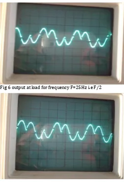
Fig 6 output at load for frequency F=25Hz i.e F/2
Fig 7 output at load for frequency F=16.66 HZ ie F/3
IX.ADVANTAGES
1 In a cyclo-converter, ac power at one frequency is converted directly lower frequency in a single conversion stage.
2 Cyclo-converter functions by means of phase commutation, without auxiliary forced commutation circuits.
3 Cyclo-converter is inherently capable of power transfer in either direction between source and load.
[image:4.595.35.284.421.586.2]© 2016, IRJET | Impact Factor value: 4.45
| Page 2448
X.DISADVANTAGES
1.Large number of thyristors is required in a
cyclo-converter, and its control circuitry becomes more complex. 2.It is not justified to use it for small installations, but is economical for units above 20 kVA.
3. For reasonable power output and efficiency, the output frequency is limited to one-third of the input frequency. 4. The power factor is low particularly at reduced output voltages, as phase control is used with high firing delay angle.
X.APPLICATION
1.Cement mill drives 2.Ship propulsion drives 3.Rolling mill drives 4.Scherbius drives 5.Ore grinding mills 6.Mine winders
XII:CONCLUSION
In this project we compare the different techniques to control the speed of induction motor. We also studied the operating principle of cycloconverter. More research has to done to control the speed of induction motor and also to reduce complex circuits due to use of many SCR. In this Project we had successfully varied the speed of cycloconverter, Cycloconverter used for Single phase motor to generate torque that matches with demand torque of particular machine by the use of designing Cycloconverter. Using PWM method we can minimizes the lower order harmonics, while filter eliminates the higher order harmonics. It provides means for limiting the slip and consequently the motor current. This means a reduction in the Cycloconverter rating and better efficiency.
XIII.REFERNCES
[1] K.V.S Bharath1,Ankit Bhardwaj2’’Implementing Single phase Cycloconverter using single phase matrix converter topology with sinusodialpilse width modulation’’ International Journal For Technological Research In Engineering Volume 2, Issue 6, February-2015.
[2]Sathish Bakanagari1, Jagadeesh Peddapudi2, A. Mahesh Kumar3,“A Novel Approch to Speed Control of Induction Motor by Cycloconverter with Thyristors ” Int. Journal of Engineering Research and Applications , Vol. 3, Issue 6, Nov-Dec 2013, pp.2159-2164.
[3] 1.B. SAI SINDURA,2. B. N . KARTHEEK , “Speed Control of Induction Motor using Cycloconverter”, International Journal of Engineering Trends and Technology (IJETT) - Volume4Issue4- April 2013.
[4] Vinamra Kumar Govil1, Yogesh Chaurasia2 ''Modeling & Simulation of PWM Controlled Cycloconverter FED Split Phase Induction Motor” International Journal of Advanced Research in Electrical, Electronics and Instrumentation Engineering Vol. 1, Issue 3, September 2012