© 2016, IRJET | Impact Factor value: 4.45 | ISO 9001:2008 Certified Journal | Page 1922
Press tool design and analysis for seat frame components
1
Madhukumar M U,
2Rthwick P,
3Puttaswamaiah s &
4Maruthi B H
1
Madhukumar M U, M-tech (Machine design), EWIT
2
Rthwick P, M-tech (Machine design),EWIT
3
Puttaswamaiah S
,Associate Pro
fessor, Dept. of Mechanical Engineering, EWIT.
4Maruthi B H. Head of mechanical dept. EWIT, Bangalore, Karnataka, India
---***---Abstract -
Press tool is an apparatus by which one can cutthe material, shape the material, material can be compressed, material can be deformed to the required shape. Press tool is a tool for cutting, forming, drawing or assembling comprising of at least punch and die used in manual or in a power press. The design is done by the Solid Works software. Three important stages are made to complete the design: in these preceding stages the design is optimized from the basic level to working level. The final design of parts is analyzed with the Ansys software. After analysis the results are compared with theoretical results and material properties for validation. After comparing the Ansys results, theoretical results found that the design is safe for further operations. Finally the cost estimation of the press tool calculated.
Key Words: Press tool, Ansys, Die, Punch, Seat frame
1.INTRODUCTION
1.1 Multiple component press tool
Multiple component press tool is the tool for more than one component accommodate in a single press tool but the pressing work will perform at different instants for the different components. The basic need of this press tool is offsetting tube by its radius to produce the flat surface. This type of operations is rarely performed by the press tool because of the cylindrical surface. This cylindrical surface to position in the die will requires the more precision surface, that surface is requires more precision machining. But in the current process in the single tube component there are more than one positions are there to offset. This process to
perform in the special purpose machine requires more time and the precision of the component is very low compared to the press tool process. In special purpose machine requires well trained operator is necessary to finish this product, but in press tool inexperienced operator can also perform very well. This is because in press tool operation the operator work is only to positioning of the component and after a stroke removing of the component from the press tool.
This press tool consists of the different parts. The different parts of press tool and their uses will be explained bellow.
Top plate: This is the major part of the top half of press tool it holds the entire top half parts. It will be further connect to the top ram of the pressing machine by slotted blots and T-grooves.
Punch back plate: Punch parts are normally hardened parts. And punches are in the top half of the press tool. In order to prevent the hardened punches to penetrate into top plate we use punch back plate.
Punch holder: This is also a plate which holds rigidly the punches in operation condition. In the punch holder pockets are there in that the punch will fit by the fasteners tighten the punch
Punches: To perform any cutting or non cutting operation punches will be used.
© 2016, IRJET | Impact Factor value: 4.45 | ISO 9001:2008 Certified Journal | Page 1923
produce the final product. It will also help to clamp the partwhile the pressing operation.
Die back plate: Normally die will be hardened. In order to prevent the die to penetrate into the bottom plate the bottom die back plate will be used.
Guide pillar and guide bush: The top and bottom half are separated for every strike and they will combine in the press condition. Therefore in order to guide the top in to the bottom half in exact position guide pillars and guide bushes will be used.
Bottom plate: Bottom plate is used to hold all the parts of the bottom half together. By this part the bottom half will be connected to the bottom ram by slotted bolts and T-groove arrangement.
Stripper plate: After punching the punch should be strip off from the component in order to strip off the punch use the stripper plate.
Strip guides: In some cases the stripper is required to guide into the bottom die for clamping purpose use stripper guides.
1.1
Components and Their Arrangement
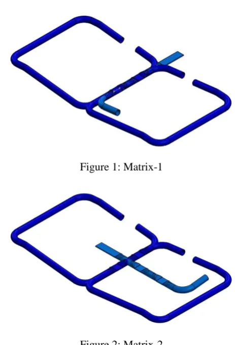
This press tool is use to produce flat surface on the automobile seat frame in the middle sections. This press tool consists of three different components of seat frame. Therefore the arrangement of the components is very important for the further design work. Primarily there are two different component arrangements are done they are called matrices. The two different matrices will be shown bellow. From these matrices the better matrix is selected for press tool design. The selected matrix is such that it is easy to operate in press tool and minimum die size condition. The component arrangement is shown in the bellow figures.
[image:2.595.314.546.92.433.2]Figure 1: Matrix-1
Figure 2: Matrix-2
For design the matrix-2 is selected and the whole design
work will on the basis of the matrix-2 arrangement.
1.2 Components Tonnage Calculation
For the components for each section calculated pressing force separately. For the three components the pressing force is same in similar section The similar section deformation force calculation is given
Component press tonnage calculations
V dr =f1 T (2 П R C1 + 0.25 L )
f1= ultimate tensile strength (N/mm2)
T=Thickness of blank (mm)
R= Corner radius between the sides (mm)
© 2016, IRJET | Impact Factor value: 4.45 | ISO 9001:2008 Certified Journal | Page 1924
C1=constant depending on ration h/Rh= deep of the drawing
R= corner radios
Component 1 and 2 calculations
f1=290MPa, T=1.6mm, R=2mm, H=10.40, L=79mm
V dr=f1 T (2 П R C1 + 0.25 L)
V dr=290 X 1.6 (2 X П X 2 X 2 +0.25 X79)
V dr=20825=20 Ton for one side
Total force required= 2X21 =40 Ton
Component 3 calculations
Section-1
f1=290MPa, T=1.6mm, R=2mm, H=10.40, L=120mm
V dr=f1 T (2 П R C1 + 0.25 L)
V dr=290 X 1.6 (2 X П X 2 X 2 +0.25 X120)
V dr=25581=25.5 Ton
Section-2
f1=290MPa, T=1.6mm, R=2mm, H=10.40, L=79mm
V dr=f1 T (2 П R C1 + 0.25 L)
V dr=290 X 1.6 (2 X П X 2 X 2 +0.25 X79)
V dr=20825=21 Ton for one side
Total force required= (2X21) + 25.5 =67.5 Ton
2. PRESS TOOL DESIGN
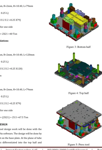
The press tool design work will be done with the help of the Solid works software. The design will be done by fixing the component on the base plate. At the plane of tube offsetting the tool is differentiated into the top half and
[image:3.595.121.527.192.787.2]bottom half. Bottom half comprises of the die, spaces, bushes, hooks. Bottom clamp holders and clamping jaws. The top half comprising of the stripper plate, punches, spacers, punch back plate, top plate, pillars and pillar clamping. The design of bottom and top half is shown in the bellow figures.
Figure 3: Bottom half
Figure 4: Top half
© 2016, IRJET | Impact Factor value: 4.45 | ISO 9001:2008 Certified Journal | Page 1925
1.2
Theoretical Calculations of the Press Tool parts
Buckling calculations
For pillars
Material= 20MnCr5
Young's modulus E =200GPa
Poisson’s ratio=3.0
Yield strength=550MPa
Diameter= 50mm
Length= 290mm
Maximum or critical force F=П2EI/(KL)2
Where,
F- Maximum or critical force
E-Modulus of Elasticity
I-Area moment of inertia
L- Unsupported length of column
K-Column effective length factor=2
F=П2X200X106XП (0.054)/4(2X0.290)2
F=28803.4 KN
σ=F/A=П2E/(l/r)2
But currently force on each pillar is 20 Ton=196.133KN
Therefore σ= 196.133/(ПX0.052/4)
σ= 99.821 MPa
In impact load condition σ max = 2 X σ
σ max= 2 X 99.821
σ max= 199.642 MPa
For guide bushes
Material= 20MnCr5
Young's modulus E =200GPa
Poisson’s ratio=3.0
Yield strength=550MPa
Diameter= 50mm
Length= 290mm
Maximum or critical force F=П2EI/(KL)2
Maximum or critical force F=П2EI/(KL)2
F= П2X200X106 X((П X0.084/4)-(П X0.06324/4))/ (2X0.140)2
F=494479.8511KN
σ=F/A=П2E/(l/r)2
But currently force on each pillar is 20 Ton=196.133KN
A=(П X0.082/4)-(П X0.06322/4)
A=1.89X10⁻³m2
σ=196.133/1.89X10-3
σ =103.802 MPa
In impact load condition σ max = 2 X σ
σ max= 2 X 103.802
σ max= 207.604 MPa
Stripper tubes
Material= EN-8
Young's modulus E =215GPa
© 2016, IRJET | Impact Factor value: 4.45 | ISO 9001:2008 Certified Journal | Page 1926
Yield strength=550MPaInternal Diameter= 17mm
Outer Diameter= 23mm
Length= 110mm
Maximum or critical force F=П2EI/(KL)2
F= П2X215X106 X((П X0.0234/4)-(П X0.0174/4))/ (2X0.110)2
F=6760.009KN
σ=F/A=П2E/(l/r)2
But currently force on each stripper tube is 4 Ton=39.24KN
A=(П X0.0232/4)-(П X0.0172/4)
A=1.885X10⁻⁴m2
σ =39.24/1.885X10-4
σ =208.169 MPa
2. ANALYSIS
The analysis of the press tool components will be done with the help of the Ansys software. The parts are primarily meshed in the Ansys software with the tetra mesh type. Finally the force is applied on those parts on the basis of the working conditions. The bellow figures show the analysis and their results.
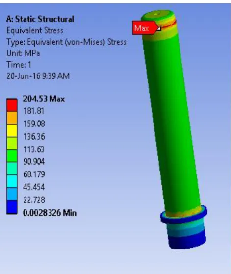
The pillar is meshed with the tetra mesh. The there are four pillar in the design each pillar will take equal load. For each pillar load is equally distributed and load of 196.133KN act on each pillar. The bellow figure shows the meshing, stress distribution and deformation in the pillar.
[image:5.595.309.559.91.347.2]
Figure 6: Pillar in meshed condition.
[image:5.595.316.552.370.650.2]© 2016, IRJET | Impact Factor value: 4.45 | ISO 9001:2008 Certified Journal | Page 1927
Figure 8: Deformation in the pillar. [image:6.595.300.558.158.370.2]similarly the analysis is done for different parts of the press tool. The analysis results will be compared with the theoretical results for the validation. For the die and punch the analysis is done. For the die we applied a load of 80 ton and die is tetra mesh condition. The stress distribution is shown bellow.
Figure 9: Stress distribution is die plate.
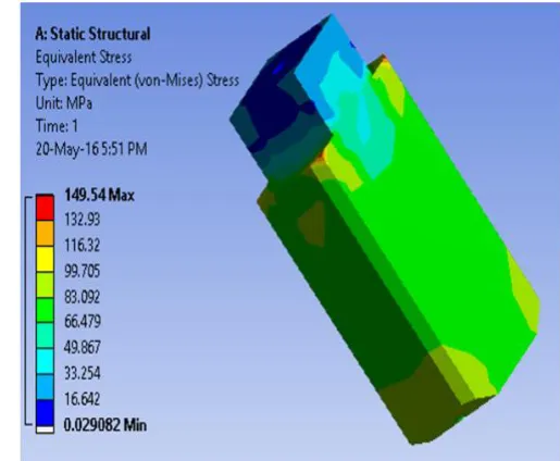
for the punch analysis is done for the load of 40 Tons and it is meshed with tetra mesh condition. The stress distribution will be shown in the bellow figure.
Figure 10: Stress distribution in punch-1.
From the analysis results and the theoretical results it is found that the design is safe.
3. CONCLUSIONS
IRJET sample template format ,Conclusion content comes here. Conclusion content comes here Conclusion content comes here Conclusion content comes here Conclusion content comes here Conclusion content comes here Conclusion content comes here Conclusion content comes here Conclusion content comes here Conclusion content comes here Conclusion content comes here Conclusion content comes here Conclusion content comes here . Conclusion content comes here
[image:6.595.37.287.523.688.2]© 2016, IRJET | Impact Factor value: 4.45 | ISO 9001:2008 Certified Journal | Page 1928
selected material bill of material is created. The analysis isdone for important components. Form validation of results shows that the design is safe in working condition. From the current project work the main advantage is multiple components will be pressed in a single press tool. It reduces the cost of other press tool for other component. It increases the productivity of the manufacturing.
REFERENCES
[1] Vishwanath M.C, Dr.Ramni and Sampath Kumar L, “Design of Progressive Draw Tool”. Volume 3, (2013), IJSRP
[2] JyothiBhaskar and G SathyaPrakash, “Die design and analysis of progressive tool for can lid lever”. Volume 1, (2013), IJREAT
[3] Mr.Amit D. Madake, Dr.Vinayak R. Naik, Mr.Swapnil and
S.Kulkarni, “Development of a Sheet-Metal Component with a Forming Die Using CAE Software Tools (Hyper form) For Design Validation and Improvement”, Vol. 3, May.-June. 2013, IJMER, p-1787-1791
[4] VrushabhMahaveerGhosarwade, and Chandradharappa, “FINITE ELEMENT ANALYSIS OF PROGRESSIVE DIE”, Volume: 02, (2015), IRJET
[5] Md Inaithul Rehaman, P Satish Reddy, Matta Manoj,
N.Guru Murthy, “Design and Analysis of Progressive Die for Chain Link Plate”, Volume 2, (2014),IJSEAT