© 2016, IRJET ISO 9001:2008 Certified Journal
Page 1715
BUS TRACKING AND MANAGEMENT SYSTEM USING GPS AND RFID
TECHNOLOGIES
Asst. Prof. Rashmi Deshmukh
1, Anuradha Vishwakarma
2, Agraja Jaiswal
3,
Ashwini Neware
4, Shruti Ghime
5, Antara Marathe
61
Assistant
Professor, Department of Computer Science And Engineering, DBACER, Nagpur, Maharashtra, India
2
Student, Department of Computer Science And Engineering, DBACER, Nagpur, Maharashtra, India
3
Student, Department of Computer Science And Engineering, DBACER, Nagpur, Maharashtra, India
4
Student, Department of Computer Science And Engineering, DBACER, Nagpur, Maharashtra, India
5
Student, Department of Computer Science And Engineering, DBACER, Nagpur, Maharashtra, India
6
Student, Department of Computer Science And Engineering, DBACER, Nagpur, Maharashtra, India
---***---Abstract –
Fleet management system maintains the recordof group of vehicles at a time. Fleet management is widely used today because it gives perfect information about the group of vehicles. The feature of such a system are accurate, robust , economical as well as flexible. Here we are using two technologies, GPS and RFID, they are used to obtain the location of bus and to identify the bus respectively. For transaction related to fuel filling is also monitored by RFID card. Thus, at server side, whole information about buses are stored in database. Thus, with minimum technologies, our goal is to develop a user friendly vehicle tracking system which provide the services to owner of transportation companies. Such a system is very useful in developing companies.
Key Words
: GPS, RFID, Bus Tracking, RFID Tag, RFID
Reader, Google Map.1.INTRODUCTION
The basic support for global economy of many industries is the transportation of services, people and goods. The owner of transportation company cannot monitor the actual movement of bus, but the owner expects quality of service in aspects of the safety assurance, time required to complete the journey, facilities provided to the passengers during travel. Vehicular tracking systems has proved to be as a useful technology for bus traveler agencies with good facilities. Bus as well as driver’s information taken care with RFID and existing location taken care with GPS.
Current tracking systems that are in use, such as barcode scanning software program, in situations where number of buses are present, the process of scanning each individual bus to check for proper placement can become a difficult task which also consumes company time and energy. The design and implementation of an vehicle tracking system, we are able to reduce the effort needed to
track and monitor a large number of targeted vehicles. This phenomenon, will allow for a more efficient vehicle tracking system that saves time as well as money while providing a simpler tracking device. Using RFID hardware , we designed a prototype which will give the information about the bus as well as driver with the amount of petrol filled by the driver. The system combines the RFID with a GPS tracking unit on PCB(printed circuit board) to provide a complete unit which is able and efficient for tracking, monitoring, and providing vehicle information in a single device. A successful and compatible system designed and implemented over the period of this project. The system can tracks many number of targeted vehicles through GPS monitoring system. New entries of driver can be easily added to the system by new registration. We can retrieve the information about driver from owner’s database.
1.1 Global Positioning System(GPS)
The Global Positioning System (GPS) is a space-based navigation system that provides location in all weather conditions. GPS satellites continuously transmit their current time and position. A GPS receiver monitors multiple satellites and solves equations to determine the exact position of the receiver and its deviation from true time. At a minimum, four satellites must be in view of the receiver for it to compute four unknown quantities (three position coordinates and clock deviation from satellite time).
1.2 Radio Frequency IDentification (RFID)
© 2016, IRJET ISO 9001:2008 Certified Journal
Page 1716
energy from a nearby RFID reader's interrogating radio waves.
2. HARDWARE
The hardware part consists of Transmitter and Receiver. Transmitter is placed on the bus and receiver is on the administrator’s side. The transmitter will transmits the values of position of the bus via GPS and when the relay is toggled it also transmits the value of RFID tag which will be scan by our RFID reader i.e. placed on our transmitter. Both GPS device as well as RFID tag transmits the alphanumeric values. The respective information which is sent by the transmitter is received by the receiver, receiver collects this information and with the help of software part all the required output will be shown on the screen.
2.1 Transmitter
A Transmitter consists of various modules like GPS module, zigbee RFID transmitter, RFID reader module and RFID tag and Relay. This transmitter will be kept on the bus and transmits the data to the receiver.
Fig.1: Transmitter
2.1.1 GPS module
A GPS is made up of constellation of satellites orbiting around Earth. Each satellite has a atomic clock on its board, so it knows the precise time. As it is orbiting around the Earth, each satellite is continuously transmitting its location at 1.575 GHz. With the help of GPS receiver pointing at the sky, we can listen to these transmissions. When listening to 3 or more satellites transmissions, we can triangulate our location on earth. Finally, with the help of the GPS receiver we could find the following:
Location
Latitude and Longitude2.1.2 Zigbee RFID Transmitter Module
This module includes some subcomponents such as: RFID module(sender) which is used to transmit data from transmitter at bus to receiver at server side. The reasons for using Zigbee RFID are that :
It requires less power of 3.3V It is secured
It provides free frequency 2.4GHz
It produces its own Personal Area Network
A 12V battery is connected to this module through which an Alternate Current (AC) is supplied. This AC is converted to Direct Current(DC) with the help of p-n junction diode and this Direct Current is pulsating. To convert this pulsating DC to smooth DC we have used capacitor filters. The whole current flowing throughout the circuit taken care with resistors. Voltage Regulator is used to provide power of 3.3V to RFID module(sender). The LEDs are used to indicate the various states of system. One is for showing Zigbee power, one is for showing connecting range and one is for indicating sending or receiving.
2.1.3 RFID reader module and RFID tag
The system is based on Radio Frequency Identification (RFID) technology and consists of a passive RFID tag. The passive micro information about the Tag ID and sends this information to the base station. The base station receives, decodes transponder tag collects power from the 125 KHz magnetic field generated by the base station, gathers and checks the information available in its Database and used to send those information. The system performed as desired with a 10cm diameter antenna attached to the transponder. RFID Reader Module, are also called as interrogators. They convert radio waves returned from the RFID tag into a form that can be passed on to Controllers, which can make use of it. RFID tags and readers have to be tuned to the same frequency in order to communicate. RFID systems use many different frequencies, but the most common and widely used Reader frequency is 125 KHz.
2.1.4 Relay
© 2016, IRJET ISO 9001:2008 Certified Journal
Page 1717
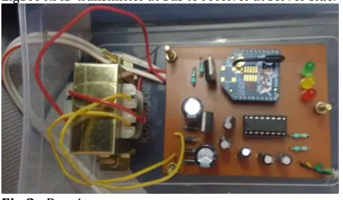
2.2 Receiver
Receiver consists of various modules like zigbee RFID Receiver and Step-down transformer. Receiver will be at the server side where all data transmitted by transmitter will be received and location is found with the help of software.
2.1.1 Step Down Transformer
Step-down Transformer is used to convert main 230V AC into 12V AC. This AC is supplied to the Receiver.
2.1.2 Zigbee RFID Receiver
[image:3.595.35.282.328.472.2]This module includes some subcomponents such as: RFID module(receiver) which is used to receive data from Zigbee RFID transmitter at bus to receiver at server side.
Fig 2 :
Receiver
The reasons for using Zigbee RFID are that : It requires less power of 3.3V
It is secured
It provides free frequency 2.4GHz
It produces its own Personal Area Network
12V AC provided by Step-down Transformer is converted to Direct Current(DC) with the help of p-n junction diode and this Direct Current is pulsating. To convert this pulsating DC to smooth DC we have used capacitor filters. The whole current flowing throughout the circuit taken care with resistors. Voltage Regulator is used to provide power of 3.3V to RFID module(receiver). The LEDs are used to indicate the various states of system. One is for showing Zigbee power, one is for showing connecting range and one is for indicating sending or receiving.
3. Software
It consist of an panel which is attached to varies electrical devices from which a single person can handles all system from one position This operations are controlled by interfacing it using buses with a personal computer. All
operations are controlled through keyboard inputs of a PC. All these executions are made possible with the help of a most powerful programming language the ‘c# language. The software is comprised of ‘Visual C#’’ language programs when executed give . The desired physical results hence all operations can be easily managed with the PC. The software part is being build afterwards. The interface consist of following fields:
1. Registration 2. Applications 3. Open port 4. Close port 5. Location 6. Bus information 7. Driver name 8. Fuel information
3.1 Registration
This menu consist of new registration form which will consist of many fields which store information about bus, as well as we can edit the form. The fig.4 shows the registration form.
3.2 Application
The Application menu contains the exit button
through which the user can exit the application.
3.3 Open Port
By clicking the open port button on interface we actually start the procedure of our system. In other words, we run our bus tracking system.
3.4 Close Port
Here we can simply stop our system means we can exist from our interface.
3.5 Location
Here we can see the location of a particular bus at a particular instant of time.
3.6 Bus Information
In this field we are getting the whole information of bus with the bus number.
3.7 Driver Name
This field consist of name of the driver.
3.8 Fuel Information
© 2016, IRJET ISO 9001:2008 Certified Journal
Page 1718
4. Result
4.1 User Interface
Fig.3:
User Interface
4.2 Open Port
Fig.4:
When the open port button is clicked, the user
can see that vehicle is moving or not.
4.3 Receiving RFID values
Fig.5:
With the use of RFID values, the user can see the
information of bus and driver of the bus.
4.4 Receiving GPS values
Fig.5:
GPS values are shown on the label named as
Location and exact location value is shown on the label
placed exactly above the open/close port.
4.5 Close Port
Fig.6:
When the close port button is clicked, the initial
stage of project will appear.
5. Conclusions
© 2016, IRJET ISO 9001:2008 Certified Journal
Page 1719
REFERENCES
[1]
Thiyagarajan Manihatty Bojan, Umamaheswaran Raman Kumar and Viswanathan Manihatty Bojan (2014), " Designing Vehicle Tracking System - An Open Source Approach", 2014 IEEE International Conference on Vehicular Electronics and Safety (ICVES), Hyderabad, India.[2]
Ramadan, M., M. Al-Khedher, and S. Al-Kheder (2012) "Intelligent anti-theft and tracking system for automobiles", Int. J. Mach. Learn. Computing .[3]
Mohammad A. Al-Khedher,( Dec 2011) Hybrid GPS-GSM Localization of Automobile Tracking System, IJCSIT Vol 3, No 6.[4]
Dr. Kamal Jain and Rahul Goel, (2012), International Conference on Traffic and Transportation Engineering (ICTTE 2012) IPCSIT vol. 26, IACSIT Press, Singapore.[5]
B. Janarthanan and T. Santhanakrishnan, "Real Time Metroplitan Bus Positionin System Desing Using Gps And Gsm".[6] CHEN Xue-Mei and WEI Zhong-Hua,( 2011), "Vehicle Management System Based on Multi-node RFID Cards" Proceedings of the 30th Chinese Control Conference.
[7] Seokju Lee, Tewolde, G. Jaerock Kwon, Design and implementation of vehicle tracking system using GPS/GSM/GPRS technology and smart phone application, Internet of Things (WF-IOT), 2014 IEEE World Forum on , vol., no., pp.353,358, 6-8 March 2014.