© 2016, IRJET | Impact Factor value: 4.45 | ISO 9001:2008 Certified Journal | Page 104
Android Phone controlled Bluetooth Robot
Rahul Kumar
1, Ushapreethi P
2, Pravin R. Kubade
3,
Hrushikesh B. Kulkarni
41
MTech. Software Engineering, VIT University, Vellore-632014, TN-India
. 2Asstt. Prof. SITE, VIT University, Vellore-632014, TN-India.
3Ph. D. Scholar, SMEC, VIT University, Vellore-632014, TN-India
. 4Ph. D. Scholar, SMEC, VIT University, Vellore-632014, TN-India
.---***---Abstract –
Robot is a reprogrammable, multifunctionaldevice which is primarily designed to do work like human such as pick and place, loading and unloading, surveillance, health care, industrial, aerospace application. Robots can perform dangerous and accurate work to increase the productivity as they can work 24 hours without rest. This paper deals with the design and control of automated vehicle type robot which can move in desired direction and captures pictures and videos of required location. An android application has developed using MIT App inventor and a bluetooth communication is made with robot which interfaces with microcontroller to control its speed and direction. Aim of this work is to design and control the motion of robot using bluetooth device of an Android phone.
Key Words: Bluetooth device, GUI (Graphical User Interface), Android OS, Smartphone, Microcontroller.
1. INTRODUCTION
A robot is an electromechanical machine that is controlled by computer program to perform various operations. Industrial robots have designed to reduce human effort and time to improve productivity and to reduce manufacturing cost. Today human-machine interaction is moving away from mouse and pen and becoming much more pervasive and much more compatible with the physical world. Android app can control the robot motion from a long distance using Bluetooth communication to interface controller and android. Microcontroller ATMEGA328P-PU
can be interfaced to the Bluetooth module though UART protocol and code is written in embedded C language.
As per the commands received from android app the robot motion can be controlled. The output motion of a robotic vehicle is accurate and repeatable. Pick and Place robots can be reprogrammable and tool can be interchanged to provide for multiple applications. The purpose of this work is to design and implement an Android Controlled Bluetooth Robot which is used for Surveillance, home automation, wheelchairs, military and hostages Rescue applications.
2. SYSTEM DESIGN AND ARCHITECTURE
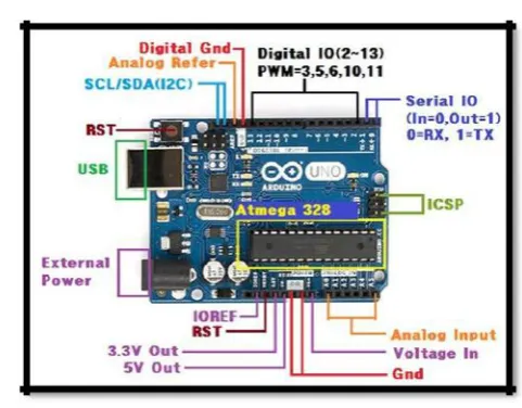
[image:1.595.308.549.260.448.2]2.1 Arduino Uno Board
Fig.-1: Arduino Uno R3
This is the brain of robot loaded by a program written in embedded c language to do the required functioning and is interfaced with bluetooth module. The motor driver are used to make the system work as required.
2.2 DC Motor
Fig. -2
: DC Motor
© 2016, IRJET | Impact Factor value: 4.45 | ISO 9001:2008 Certified Journal | Page 105 machines with parts the size of red blood cells and find many
applications in medicine.
2.3 Uart
Universal asynchronous receiver/ transmitter is usually an individual integrated circuit used for serial communications for computer or peripheral device serial port. UART are now commonly used in microcontrollers. A dual UART combines two UARTS into a single chip. Many modern ICs come with a UART that can also communicate synchronously; these devices are called UART. UARTs are commonly used in conjunction with communication standards such as TIA (formerly EIA) 232, 422 or RS-485. The universal designation indicates that the data format and transmission speeds are configurable. The electric signaling levels and methods (such as differential signaling etc.) are handled by a driver circuit external to the UART. The UART takes bytes of data and transmits the individual bits in a sequence. At the destination, a second UART re-assembles the bits into complete bytes. Each UART contains a shift register, which is the fundamental method of conversion between serial and parallel forms. Serial transmission of digital information (bits) through a single wire or other medium is less costly than parallel transmission through multiple wires.
2.4 L293D Motor Driver IC
Microcontroller cannot supply the current required to run DC motor. So satisfy this requirement IC’s are used to drive the motor. The L293 and L293D are quadruple high-current half –H drivers. The L293D provides bidirectional drive currents of up to 1A at voltage from 4.5V to 36V. The L293D is designed to provide bidirectional drive currents of up to 600-MA at voltages from 4.5V to 36V. Both devices are designed to drive inductive loads such as relays, solenoids, dc and bipolar stepping motors, as well as other high-current/high voltage loads in positive-supply applications. On the L293D, external high-speed output clamp diodes should be used for inductive transient suppression. A Vcc1 terminal, separate from Vcc2, is provided for the logic inputs to minimize device power dissipation. The L293 and L293D are characterized for operation from 0ↄC to 700C.
2.5 Working of L293D
The 4 input pins for this l293d, pin 2, 7on the left and pin 15, 10 on the right as shown on the pin diagram. Left input pins will regulate the rotation of motor connected across left side and right input for motor on the right hand side. The motors are rotated on the basis of the inputs provided across the input pins as LOGIC 0 or LOGIC 1.In simple you need to provide Logic 0 or 1 across the input pins for rotating the motor.
2.6 L293D Logic Table
Consider a Motor connected on left side output pins (pin 3, 6). For rotating the motor in clockwise direction the input pins has to be provided with Logic 1 and Logic 0.
Pin 2 = Logic 1 and Pin 7 = Logic 0 | Clockwise Direction
Pin 2 = Logic 0 and Pin 7 = Logic 1 | Anticlockwise Direction
Pin 2 = Logic 0 and Pin 7= Logic 0 | Idle [No rotation]
Pin 2 = Logic 1 and Pin 7 = Logic 1 | Idle [No rotation]
In a very similar way the motor can also operated across input pin 15, 10 for motor on the right hand side.
Consider a Motor connected on right side output pins (pin 11, 14). For rotating the motor in clockwise direction the input pins has to be provided with Logic 1 and Logic 0.
Pin 15 = Logic 1 and Pin 10 = Logic 0 | Clockwise Direction
Pin 15 = Logic 0 and Pin 10 = Logic 1 | Anticlockwise Direction
Pin 15 = Logic 0 and Pin 10= Logic 0 | Idle [No rotation]
Pin 15= Logic 1 and Pin 10 = Logic 1 | Idle [No rotation]
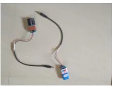
2.7 Power adaptor
[image:2.595.308.419.522.606.2]This is used to give appropriate DC power supply (9 V) to microcontroller, Driver IC sensors and other passive components of the Robot.
Fig. -3: Power adaptor with 9 V battery.
2.8 HC-05 Bluetooth module
© 2016, IRJET | Impact Factor value: 4.45 | ISO 9001:2008 Certified Journal | Page 106 running on android, laptops and
Fig. -4
: HC -05 Bluetooth module.
computers. It is very handy as it can be easily fitted with a module to allow Bluetooth communication. Bluetooth is the only appropriate communications protocol that has no fear of getting the frequency interferences because it uses the MAC Address of the device i.e. Bluetooth allows the connectivity between two devices using their MAC Address.
HC-05 module shown in Figure-1 is an easy to use Bluetooth SPP (Serial Port Protocol) module, designed for transparent wireless serial connection setup. Serial port Bluetooth module is fully qualified Bluetooth V2.0+EDR (Enhanced Data Rate) 3Mbps Modulation with complete 2.4GHz radio transceiver and baseband. It uses CSR Bluecore 04-External single chip Bluetooth system with CMOS technology and with AFH (Adaptive Frequency Hopping Feature). HC-05 module work on 3.0V low power operation and 3.0 to 4.2V I/O controls. It has integrated antenna, edge connector and UART interface with programmable baud rate. HC-05 module has default Baud rate: 38400, Data bits:8, Stop bit:1,Parity: No parity and supported baud rates are 9600, 19200, 38400, 57600, 115200, 230400, 460800.
[image:3.595.35.145.120.230.2]3. SYSTEM ARCHITECTURE
Fig. -6
: System Architecture of proposed system
Fig. -5: Block diagram of proposed system
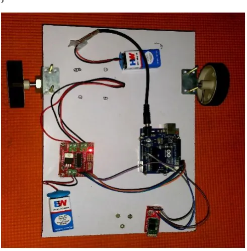
A robot can be controlled using Bluetooth module HC-05 and ATMEGA328P-PU microcontroller with android Smartphone device. The controlling devices of the whole system are a microcontroller. Bluetooth module, DC motors are interfaced to the microcontroller.
The data receive by the Bluetooth module from android smart phone is fed input to the controller. The controller acts accordingly on the DC motor of the robot. The robot can move to move in all the four directions using the android phone. The direction of the robot is indicators using LED indicators of the Robot system. In achieving the task the controller is loaded with program written using Embedded ‘C’ Languages. Android smart phone controller Bluetooth
Fig. -7
: Sequence Diagram1
POWER SUPPLY
Arduino unoBoard
(Micro controller)
ATMEGA328P -PU
Motion control circuit
[image:3.595.294.561.475.742.2]© 2016, IRJET | Impact Factor value: 4.45 | ISO 9001:2008 Certified Journal | Page 107
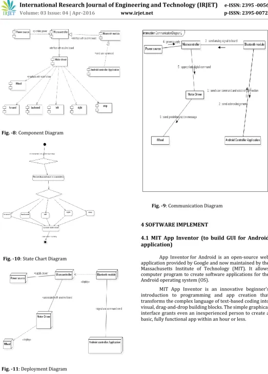
Fig. -8
:
Component Diagram [image:4.595.33.557.46.776.2]Fig. -10
:State Chart DiagramFig. -11: Deployment Diagram
Fig. -9
: Communication Diagram4 SOFTWARE IMPLEMENT
4.1 MIT App Inventor (to build GUI for Android
application)
App Inventor for Android is an open-source web application provided by Google and now maintained by the Massachusetts Institute of Technology (MIT). It allows computer program to create software applications for the Android operating system (OS).
© 2016, IRJET | Impact Factor value: 4.45 | ISO 9001:2008 Certified Journal | Page 108
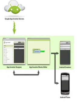
Fig. -12: Working of MIT APP
Inventor
App Inventor involves three aspects:
(i) App inventor designer,
(ii) App Inventor Blocks editor, and (iii)An emulator or Android Phone.
The set-up process for the software is very easy and system requirements are very basic. It is compatible with Mac OSX, Windows and Linux Operating systems. Browsers required for the software are Mozilla Firefox 3.6 or higher, Apple Safari 5.0 or higher, Google Chrome 4.0 or higher and Microsoft Internet Explorer 7.0 or higher. (App Inventor 2012)
4.2 App Inventor Designer
[image:5.595.42.297.100.439.2]The first phase of application design passes through App Inventor Designer. Designer is accessible through the web page and all the ingredients for the app are available on the left side of the window. The ingredients contains elements like a screen for the app, buttons for tapping, text boxes, images, labels, animations and many more. The right side of the designer allows users to view the screen and components added to the screen. Additionally, the properties section of the window allows users to modify the properties of components.
Fig. -13
:
App inventor DesignerAdding the components to the screen is a simple drag-and-drop process. The alignment of the components can be managed through alignment options. Several non-visible components are also added to the screen, which are explored later in the blocks editor. On the left of the screen is a list of the components which can be dragged and dropped onto the Android screen. To the immediate right of the Android screen is a list of the current screen components: a ListPicker, two Buttons in a Horizontal Arrangement and a “hidden” Label, hidden because it is initially blank. There is also a non-visible bluetooth client at the bottom of the screen. To the far right of the Android screen are the properties of the currently selected component - in this case the Label, Label1 is selected. If we click on the Blocks Tab and then click on the ListPicker1 component on the left hand side of the screen. A scrollable list of code blocks relevant to theListPicker1 appears.Click on“When ListPicker1 BeforePic king” and it will be placed onto the Blocks screen area.
Fig. -14:Inventor App inventor Block Editor
[image:5.595.309.559.546.713.2]© 2016, IRJET | Impact Factor value: 4.45 | ISO 9001:2008 Certified Journal | Page 109 The next Block allows ListPicker1 to select and connect to
the desired Bluetooth device and to set the “hidden” Label, Label1 to read “CONNECTED”
Set the default Text of Label1 to be “NOT CONNECTED” and the colour of Label1 to be Red in the Design Screen; clearly, Label1 is now no longer “hidden”. Add a further component into the code Block, to set the Text colour of Label1 to be Green when the Bluetooth client is connected.
4.3 An emulator or Android phone
[image:6.595.308.561.203.437.2]The final part of the application design is testing the application. Thus, for the users without the android handsets. App Inventor gives the option of testing the application in an emulator which is very similar to the real device but with some limitations. From the Blocks Editor, the user can connect the application to the emulator available via the connect option and test how the application functions in real world. Apart from the emulator, the user can also directly connect the android phone to the computer via USB connecter and test the application. Real time testing is definitely the best option for monitoring the application function.
Fig. -16
:
Android Emulator5. ANDROID APPLICATION
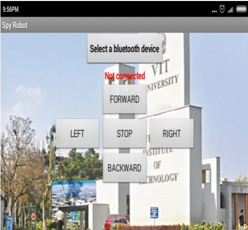
Spy Robot is the name of the android application designed for this project. It was designed through App Inventor. The basic function of the application is to control the robot (created with Arduino and Chassis). It has different buttons integrated to it and each button has different functions.
Fig. -15: Spy Robot application layout
5.1 Buttons
There is a total of six buttons in the application. One of them are for preparing the device to communicate with the robot. Four of them are for commanding the directions. One is for stopping the motion of robot
5.2 Set Device and Connect Buttons
The first button is the set device button. When the button is tapped the application takes the user to a window with the list of Bluetooth devices available. Tapping the right device allows the user to come back to the main window which awaits the user with the activated connect button which when clicked connects the application to the robot allowing the user to use other buttons available.
5.3 Software Tools: Ardunio
[image:6.595.35.237.539.753.2]© 2016, IRJET | Impact Factor value: 4.45 | ISO 9001:2008 Certified Journal | Page 110
[image:7.595.32.294.102.286.2]Fig. -17:Arduino Emulator
Programming Digital I/O pins of Arduino UNO board:
• Each pin is controlled by three commands associated with it which are designated as:
pinMode()
digitalWrite()
digitalRead()
• pinMode()
This configures the specified pin to behave either as an input or an output.
Syntax
pinMode(pin, mode)
Parameters
pin: the number of the pin whose mode you wish to set
mode: INPUT, OUTPUT.
Returns
None
Example
intledPin = 13; // LED connected to digital pin 13
void setup()
{
pinMode(ledPin, OUTPUT); // sets the digital pin as output
}
void loop()
{
digitalWrite(ledPin, HIGH); // sets the LED on
delay(1000); // waits for a second
digitalWrite(ledPin, LOW); // sets the LED off
delay(1000); // waits for a second
}
• digitalWrite()
Write a HIGH or a LOW value to a digital pin.
If the pin has been configured as an OUTPUT with pinMode(), its voltage will be set to the corresponding value: 5V (or 3.3V on 3.3V boards) for HIGH, 0V (ground) for LOW.
Syntax
digitalWrite(pin, value)
Parameters
pin: the pin number
value: HIGH or LOW
Returns
None
Example
Sets pin 13 to HIGH, makes a one-second-long delay, and sets the pin back to LOW.
intledPin = 13; // LED connected to digital pin 13
void setup()
{
pinMode(ledPin, OUTPUT); // sets the digital pin as output
}
void loop()
{
digitalWrite(ledPin, HIGH); // sets the LED on
delay(1000); // waits for a second
© 2016, IRJET | Impact Factor value: 4.45 | ISO 9001:2008 Certified Journal | Page 111 delay(1000); // waits for a second
}
• digitalRead()
Reads the value from a specified digital pin, either HIGH or LOW.
Syntax
digitalRead(pin)
Parameters
pin: the number of the digital pin you want to read (int)
Returns
HIGH or LOW
Example
intledPin = 13; // LED connected to digital pin 13
intval = 0; // variable to store the read value
void setup()
{
pinMode(ledPin, OUTPUT); // sets the digital pin 13 as output
}
void loop()
{
val = digitalRead(inPin); // read the input pin
digitalWrite(ledPin, val); // sets the LED to the button's value
}
6. IMPLEMENTATION SOURCE CODE
Fig.-18:Bluetooth with motor control device
Fig.-19: led control using Bluetooth
© 2016, IRJET | Impact Factor value: 4.45 | ISO 9001:2008 Certified Journal | Page 112 int a;
int led=13;
int motor1=2; //leftmotor up
int motor2=3; //leftmotor down
int motor3=4; //rightmotor up
int motor4=5 ; //rightmotor down
void setup() {
pinMode(motor1,OUTPUT);
pinMode(motor2,OUTPUT);
pinMode(motor3,OUTPUT);
pinMode(motor4,OUTPUT);
pinMode(led,OUTPUT);
Serial.begin(9600);
}
void loop() {
a=Serial.read();
if(a=='1')
{
digitalWrite(motor1,HIGH);//forward
digitalWrite(motor2,LOW);
digitalWrite(motor3,HIGH);
digitalWrite(motor4,LOW);
}
if(a=='2')
{
digitalWrite(motor1,LOW);
digitalWrite(motor2,HIGH);
digitalWrite(motor3,LOW);//backward
digitalWrite(motor4,HIGH);
}
if(a=='3')
{
digitalWrite(motor2,LOW);//right
digitalWrite(motor1,HIGH);
digitalWrite(motor3,LOW);
digitalWrite(motor4,LOW);
}
}
if(a=='4')
{
digitalWrite(motor1,LOW);
digitalWrite(motor2,LOW);
digitalWrite(motor4,LOW);//left
digitalWrite(motor3,HIGH);
}
if(a=='5')
{
digitalWrite(motor1,LOW);//stop
digitalWrite(motor2,LOW);
digitalWrite(motor3,LOW);
digitalWrite(motor4,LOW);
}
}
LED Control Using Bluetooth
int a;
int led=13;
void setup() {
pinMode(led,OUTPUT);
Serial.begin(9600);
© 2016, IRJET | Impact Factor value: 4.45 | ISO 9001:2008 Certified Journal | Page 113 void loop() {
a=Serial.read();
if(a=='1')
{
digitalWrite(led,HIGH);
delay(1000);
}
else
digitalWrite(led,LOW);
[image:10.595.35.281.304.554.2]}
Fig. -20:Android phone controlled bluetooth robot
7. APPLICATIONS
In Domestic Use: This project can be used at homes for many purposes like picking up and placing some objectsfrom one to other.
In Spying Operations: This robot can help in spying operations. The object recognition and android control makes it Hi-Fi.
For Handicapped People: This project can help the handicapped people especially those who had lost their feet unfortunately.
Robo Races: The tilt control of robots can be used in robo races which will be revolutionary.
Miltary Application and Hostage Rescue
8. CONCLUSIONS
The operating system of smart phone is android which can develop effective remote control program. At the same time , this program uses blue-tooth connection to communicate with robot. It has proven to allow for meaningful two-way communication between the Android phone and the robot which would allow a non-expert to interact with and adjust the functionality of a system which uses ATmega328 controller, a single board micro-controller intended to make the application of interactive objects or environments more accessible. The surveillance is always has been a quite sensitive task. And it includes so many risks. So it’s better to use robot for this job instead of people. And if you are able to control the robots with efficiency and accuracy then you can guarantee yourself with good results and success. This system is a good step for secure surveillance using robots.
Wireless control is one of the most important basic needs for all the people all over the world. But unfortunately the technology is not fully utilized due to a huge amount of data and communication overheads. Generally many of the wireless-controlled robots use RF modules. But our project for robotic control make use of Android mobile phone which is very cheap and easily available. The available control commands are more than RF modules. For this purpose the android mobile user has to install a designed application on her/his mobile.
9. FUTURE SCOPE
A wireless camera is mounted on the robot vehicle for spying and surveillance purpose even in night time by using infrared lighting. Future modifications can be made to perform different tasks with precise control such as:
A Robot Mounted with camera
A headset, with a full-color display
A mission control centre
REFERENCES
[1] Arvind Kumar Saini1,Garima Sharma2, Kamal Kishor
Choure3, “BluBO: Bluetooth Controlled Robot,” International Journal of Science and Research (IJSR) National Conference on Knowledge, Innovation in Technology and Engineering (NCKITE), 10-11 April 2015, pp. 325-328S
.
[2] Arpit Sharma1, Reetesh Varma2, Saurabh Gupta3 and
Sukhdeep Bhatia4, “Android Phone Controlled Robot Using Bluetooth” IJEEE ISSN 0974-2174, Volume 7, Number 5 (2014, pp. 443-448)
[3] M.Selvam1, “Smart phone based robotic smart phone
based robotic” IJRET Volume: 03 Issue: 03, Mar-2014, pp. 229-232.
[4] Ritika Pahuja1, Narender Kumar2, “Android Mobile
© 2016, IRJET | Impact Factor value: 4.45 | ISO 9001:2008 Certified Journal | Page 114 Microcontroller” IJSER, Volume 2 Issue 7, July 2014,
Paper ID: J2013324, pp. 14-17.
[5] Aniket R. Yeole1, Sapana M. Bramhankar2, Monali D.
Wani3, Mukesh P. Mahajan4, “Smart Phone Controlled
Robot Using ATMEGA328 Microcontroller”, IJIRC Vol. 3, Issue 1, January 2015, pp. 352-356
[6] Aiman Ansari *1, Yakub Ansari*2, Saquib Gadkari*3, Aarti
Gokul#4, “Android App Based Robot, IJCSIT, Vol. 6 (2) , 2015, pp.1598-1600
[7] Arita Dey 1, Akash Pal 2, Sayantan Nandi 3, Lusika Roy 4,
“Three way controlled android Smartphone based robotic vehicle via Bluetooth”, IJARCCE, Vol. 4, Issue 9, September 2015, pp. 212-216.
[8] Muhammad Gulfam1 and Mirza Waleed Iftikhar Baig2,
“WG11 Android based Surveillance Robot
Control”IJMSE,Vol. 3, March 2015, pp. 17-22
BIOGRAPHIES
Rahul Kumar M. Tech. Scholar in Software Engg., from SITE VIT University, Vellore, TN-India.
Prof. Mrs. Ushapreethi P. Asstt. Prof. SITE, VIT University, Vellore-632014, TN-India.
Pravin R. Kubade did Dip., B.E., and M.E. in Mech.-Prod. Engg. from Govt. College of Engg., Karad, Maharashtra-India. Currently pursuing Ph. D. in Mechanical Engg. From SMEC VIT University, Vellore, TN- India.
Hrushikesh B. Kulkarni did B.E.,Mech. Engg. and M Tech. in Energy technology from Shivaji University, Kolhapur, Maharashtra-India. Currently pursuing Ph. D. in Mechanical Engg. From SMEC VIT University, Vellore, TN- India.