© 2016, IRJET | Impact Factor value: 4.45 | ISO 9001:2008 Certified Journal
| Page 1314
Design, Analysis and Manufacturing of a Set of Stage Tools for sheet
metal component for a Panel Back Outer Rear Back Floor
Sridhar H S
1, Harendra kumar H V
2, A R Mohan kumar
3, Dinesh P
4,
Satish.P.C
5,
Umashankr.K.T
61-6
Assistant Professors
Department of Mechanical Engineering.
Sri Krishna institute of Technology Banglore-90, Karnataka, India.
---***---Abstract -
This dissertation work covers theDesign, Analysis and Manufacturing of a Set of Two Stage Tools for the Panel Pack Outer Rare Floorn of an automobile component. The customer gave the component drawing it involves the press operations like Drawing, Trimming, Piercing and Flange, Re-strike respectively. Considering the size of operations in the component and the production volume we decided for a set of two stage tools. The alternative is a progressive tool which is not practical in this project because a large number of operations are required and difficult to control the dimensions and movement of the strip at subsequent operations in progressive die. It was decided to go for two stage tools. Covering the press operations like Drawing, Trimming & Piercing and Flange & Re-strike operations are performed by a set of two separate stage tools required such as Drawing tool and Gang tool. The First stage of drawing operation takes place in drawing tool and Second stage of Trimming & Piercing and Flange & Re-strike operations are simultaneously takes place in Gang Tool respectively.
Key Words: Drawing, Trimming, Flange, piercing, press tool.
1. INTRODUCTION
The Metal Stamping Die known as Press Tool is an ideal tool that can produce large quantities of parts consistent in appearance, quality and dimensional accuracy. Stampings are one of the most important semi finished products and sheet metal forming technology is an important engineering discipline within the area of mechanical engineering. Components made from Sheet metals [1] account to over 30% of the components in Automobile, over 20% in Aerospace and find wide ranging applications in various areas of electrical, electronics and consumer products.
Traditionally development of press tools has been accomplished manually drafting the design outline of the press tool. The entire development longer lead time and involved lot of trials and reworking before the component
was acceptable from the surface finish and dimensional point of view.
This dissertation work covers the Design, Analysis and Manufacturing of a Set of Two Stage Tools for the Panel Pack Outer Rare Floorn of an automobile component ismade up of CRCA (Cold Rolled Cold Annealed) sheet material. The design of a progressive tool with different stage tools performs the different cutting and non-cutting operations are involved in the design of two different stage tools, are more complex and highly specialized procedure [1].
The diverse nature of sheet metal component consists of four basic operations such as drawing operation is produced by drawing tool and other two operations are trimming- piercing and flanging - re-striking are simultaneously takes place in a gang tool at two different stages. The design of the tool is aimed for a high productivity and to obtain good quality of products economically.
1.1
STATEMENT OF THE PROBLEM
Design, Analysis and Manufacture of two components per stroke to manufacture a set of stage tools to produce a component of “Panel Pack Outer Rear Floorn for Car of an automobile vehicle” is the task in this project.
Design of the press tools is accomplished by usage of CAD package Unigraphics. Design of the tool comprises Solid Modeling of Parts, assembly of components and detailed drawings. The design of the tool is carried out in accordance with the empirical formulae listed in Hand books/ standards and rule of thumb practiced in industry.
A new component is usually manufactured without giving enough attention to simulation and analyses aspects, by trial and error process in order to obtain a part without defects. Even the previous experience of designers is not enough to decrease the number of trial, rework on tool and redesign cycles.
© 2016, IRJET | Impact Factor value: 4.45 | ISO 9001:2008 Certified Journal
| Page 1315
1.2
OBJECTIVE OF THE STUDY
The main objective of the dissertation work is to increase production while maintaining quality, lowering costs and to maintain the desired degree of repeatability from one part to the next. To this end work realized, by improved scientific and empirical aspects in the current status of the design and fabrication of press tools.
The dissertation work is to develop an improved understanding of the scientific and empirical aspects in the current status of the design and fabrication of press tools. Aim is to generate tools faster, cheaper and in a better manner.
A large number of parameters such as the physical and mechanical properties of the sheet metal, component geometry, and equipment employed, process parameters selected, number of components manufactured, economic market dynamics, impact on the design of press tools. There are complex since they are multiply coupled.
Hence Decision making on the type, number of tools, specific elements and choice of the material for fabrication and its generation protocol is a challenging task. Any effort at making this exercise more scientific is of the highest values.
2. LITERATURE SURVEY
A great deal of influence of development technology of progressive die for press tooling\ as a top rapidity operation with a minimizing costs is given to the production part by many kinds of factors, i.e. the complexity of die components of machining and its assembling, pressing machinery capacity, lot size of production part, materials of die components and its heat treatment, etc. The interactions of a whole of many factors to the die development with a optimized method are concerned by tool engineers. The important role of tool engineers is strip process layout design and computer aided simulation with a existing data base and abundant field experiences. The prediction of result on the tryout is critical division on the die development.
Press working involves the manufacture of sheet metal components by shearing and plastic deformation. There are various types of operations involved, and the complexities depend upon the type, shape, material involved, and the accuracy required. There are different types of presses for producing pressed parts. The primary requirement is to design a die required to produce the component. The different types of presses involved, types of operations and various kinds of dies used in press working.
In this chapter a review of the literature focusing on the most recent experimental and numerical studies conducted on sheet metal stamping processes will be presented for a male and a female die for the proper forming of a finished part.
Sheet metal is one of the most important semi finished products used in the steel industry, and sheet metal forming technology is therefore an important engineering discipline within the area of mechanical engineering. Sheet metals are characterized by a high ratio of surface area to thickness. Sheet metal forming is basically conversion of a flat sheet metal into a product of desired shape without defect like fracture or excessive localized thinning.
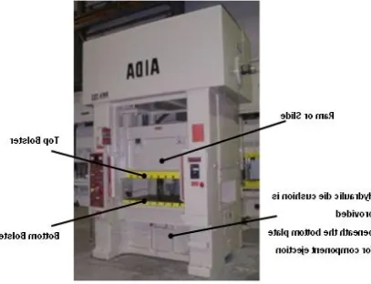
[image:2.595.357.561.487.643.2]In automobiles the sheet metal is deformed into the desired and brought into the required form to get auto body pressings like bonnet, bumpers, doors, etc. In aircraft’s sheet metal is used for making the entire fuselage wings and (body). In domestic applications sheet metal is used for making many parts like washing machine body and covers, iron tops, timepiece cases, fan blades and casing, cooking utensils etc. here. Conclusion content comes here Conclusion content comes here Conclusion content comes here Conclusion content comes here Conclusion content comes here Conclusion content comes here Conclusion content comes here Conclusion content comes here Conclusion content comes here Conclusion content comes here Conclusion content comes here Conclusion content comes here . Conclusion content comes here
© 2016, IRJET | Impact Factor value: 4.45 | ISO 9001:2008 Certified Journal
| Page 1316
2.1.1
PURPOSE OF DIE SETS
The purpose of a die set is to unitize the entire die assembly. Some of the advantages realized by assembling die components to a properly selected die set are [10]
Accuracy of setup: - The die can be installed in the press as a self-contained unit, assuring proper alignment of the various punch and die members.
Improved piece-part Quality: - By achieving better accuracy level and surface finish in the tool part quality is enhanced. Increased die life: - This is a result of proper alignment. Minimum set up time: - Set up time is kept to the minimum because the die is installed as a unit.
Facilitation of Maintenance: - Die components can be removed and reassembled without disturbing their relationship to each other. Cutting components can be sharpened in assembly, as units, without removing them from the die set. This can be a distinct advantage over removing the components and sharpening them as separate pieces.
Alignment of Punch and Die Members: - A die set can be a means of keeping the punch and die members properly aligned during the working process. However, a die set cannot be expected to compensate for a punch press, which is not in good condition. Neither should a die set be expected to operate satisfactorily if heavy, unbalanced work forces exist. Such loads should be compensated for in the design of the die; they should not be transferred to the guideposts and bushings of the die set.
Facilitation of storage:- On completion of the production run, the die can be stored as a unit ready to be placed in production again immediately.
Fig.2.1.1 Exploded view of Die set.
3. PROGRESSIVE DIES
Progressive dies for producing sheet metal parts in mass production have been widely applied in various industries such as aerospace, electronics, machine tools, automobiles, and refrigeration. These dies can perform piercing, notching, cut-off, blanking, lancing, bending, shaving, drawing, embossing, coining, trimming, and other miscellaneous forming operations at a single setup. Hence a progressive die is generally very complex. Stamping process planning and die structure design are difficult and demanding tasks [7, 18,].
Stamping process planning starts with an unfolding of a model of stamped metal part to produce a flat pattern, followed by nesting the pattern to produce a blank layout. Next, stamping operations are planned and operations are assigned to die stations. The resulting plan is typically represented as a strip layout, which guides the subsequent die structure design. The productivity, accuracy, cost, and quality of a progressive die mainly depends on the strip layout, and hence a stamping process. However, stamping process planning still remains more of an art rather than a science. Historically, this activity is mainly carried out manually, based on designers’ trial-and-error experience, skill and knowledge.
Recent advances in the field of artificial intelligence (AI) have given rise to the possibility of constructing AI based systems that incorporate built-in intelligence and apply diverse knowledge to solving progressive die design problems, including strip layout design automation. The diverse knowledge sources (KS’s) related to stamping process planning include unfolding knowledge to produce a flat pattern, nesting knowledge to produce a blank layout, various types of planning knowledge for different stamping operations like piloting, piercing, notching, cut-off, blanking, bending, etc., and staging knowledge to sequence the stamping operations. A discussion of some knowledgebase progressive die design work related to our study can be found in the next section. However, the existing work is based on the conventional architecture of knowledge based expert systems, which are incapable of managing heterogeneous KS’s effectively. In addition, this work doesn't provide a representation scheme for experts to model their valuable, but difficult-to-articulate, knowledge in terms with which they are familiar.
© 2016, IRJET | Impact Factor value: 4.45 | ISO 9001:2008 Certified Journal
| Page 1317
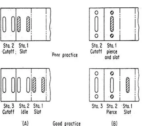
Fig.3.1 Use of three-stage die to avoid weak die block:
(A) Pierced hole close to edge of part
(B) Pierced hole closed together.
4. METHODOLOGY
The following methodology was followed during this project [10].
1) Each day it started with a QCM (Quick Corner meeting). In that we all the designers in the department form a circle and first one of us read out the quality policy of the company. Later on we discussed the events taken place the previous day. Upto date of each job. Further on discussed on the activity that each designer has to do on that day. If any new projects are coming or any changes are taking place on the particular project that will be also discussed in the QCM. It will be over within 15 minutes.
2) The project started with the preparation of concept drawings for all the tools. The no. of tools for each component was finalized in the customer meeting done by our M.D and chief designer before starting the concept drawing.
3) Review of the concept drawings was done with the chief designer.
4) Incorporating the necessary changes in the concept drawing the assembly drawing preparation was started.
5) Bill of materials was prepared and the reference copy of the assembly drawing for acquiring the materials was released.
6) Later on started on the Part drawing.
7) After having design review meeting on the part drawings between the designers and the chief designer the controlled copy of the drawings where released for tool manufacturing. One set of drawing for each tool will be kept in the files and soft copy for future reference and modification. This is called the master copy files.
8) For the tools which require wire cut data, it has to be provided in autocad format. The die, shedder, punch holder has to be wire cut.
9) The tool elements which have 3D profiles has to be provided with 3D Data for CNC machining. The 3D data was given in the form of Pro-E files. Mainly the punch profiles has to be given 3D data for manufacturing.
Component Description. Selection of Sheet Metal. Solid modeling of the Tool. Tool fabrication and assembly.
5. TOOL DESIGN
5.1
INTRODUCTION
In the first few sections of this chapter, Step by step approach to design of Press Tools based on experience, empiricism and expertise and various design calculations are introduced. The importance of material selection for the tool is also discussed [12].
5.2
COMPONENT DRAWING
Essential and critical dimensions, notes on
tolerances, finish etc, component material, and thickness is noted. Each specification, critical dimensions, must be studied to understand exactly what the product engineer specifies.
[image:4.595.314.563.568.717.2]© 2016, IRJET | Impact Factor value: 4.45 | ISO 9001:2008 Certified Journal
| Page 1318
5.2.1
AUTOFORMSIMULATION SOFTWARE
[image:5.595.313.564.163.413.2]Based on Auto Form-Die Designer's clear and logical structure, feasibility engineers are guided step-by-step from the import of CAD part geometry until the full die face design, a process which the software greatly speeds up. As a result, process planners can generate several different tooling concepts in a single day, rather than manually designing only a few individual faces with a CAD system. Auto Form-Die Designer's powerful features, ease-of-use and productivity have made it the software of choice for die engineering and tooling departments worldwide. Auto Form offers a complete, integrated software solution for the sheet metal forming industry. Its range of application comprises specialized modules for each phase of the product development – from product concept to final production tooling.
Fig 5.2.1 Draw completion & Trim initiating
Fig 5.2.2 Formability Chart
5.3
Final Component
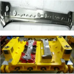
Fig 5.3.1 show the Top Half of Gang Tool
6. CONCLUSION
The project under taken has been successfully accomplished by approaching the problem scientifically. Several imperfects in the design of tooling for the manufacture of components by stamping of sheet metal were decided upon primarily on a critical examination.
Components were achieved by trail and error determination of the blank. A previous component has wrinkle marks on the flange. Which are eliminated in this design? So the aesthetic look of the component was good.
Carrying out a design exercise, followed by fabrication, validation by small batch of production.
[image:5.595.57.291.365.556.2]© 2016, IRJET | Impact Factor value: 4.45 | ISO 9001:2008 Certified Journal
| Page 1319
REFERENCES
[1] A Hybrid Intelligent System for Stamping, Process
Planning in Progressive Die Design By W. Y. Zhang a, S. B. Tor a, b and G. A. Britton, Singapore-MIT Alliance.
[2] Identifying Sources of Variation in Sheet Metal Stamping
by Karl D. Majeske,TheUniversity of Michigan, The University of Michigan Business School and Patrick C. Hammett, The University of Michigan,Transportation Research Institute.
[3] Techniques of Press Working Sheet Metal, Donald F.
Eary and Edward A. reed.
[4] An Expert System for Design of Blanking Dies for Sheet
Metal Operations by S. Kumar, R. Singh, and G.S. Sekhon.
[5] D. Eugene Ostergaard, “Basic Die making”, McGraw-Hill,
1986.
[6] Dr.John G. Nee, “Fundamentals of Tool Design”, Society
of Manufacturing Engineers, Fourth Edition, 1998
[7] Integrated Process Simulation and Die-Design in Sheet
Metal Forming by M. Tisza1, Zs. Lukács2, G. Gál3, University of Miskolc – H-3515 Miskolc-Egyetemváros, Hungary.
[8] Cold Working Die Steel Standard by ASSAB SRIPAD
STEELS LTD.
[9] Press tools Design & Constructions, Prakash H.Joshi,
Wheeler Publishing, 1999.
[10] By Hishida, Yuji, Wagoner and Robert, Die Design Hand
Book, David a.Smith, McGraw- Hill, 1991.
[11] Design Tool Engineering Parameters by GTTC Standard. [12] Tool Engineering Parameters, ISTE (CITD).
[13] O.P.Khanna and M Lal, Production Technology Vol –I,
1996.
[14] Kalpakjain, “MANUFACTURING ENGINEERING AND
TECHNOLOGY”, Addison- Wesley Publishing Company, 2000.
BIOGRAPHIES:
“SRIDHAR .H. S”
Assistant Professor Dept of mechanical engineering
S.K.I.T Banglore-90
“ HARENDRA KUMAR.H.V“
Assistant Professor Dept of mechanical engineering
S.K.I.T Banglore-90
“ A.R. MOHAN KUMAR“
Assistant Professor Dept of mechanical engineering
S.K.I.T Banglore-90
“DINESH.P “
Assistant Professor Dept of mechanical engineering
S.K.I.T Banglore-90
“SATISH.P.C“
Assistant Professor Dept of mechanical engineering
S.K.I.T Banglore-90
“UMASHANKR.K.T“
Assistant Professor Dept of mechanical engineering
S.K.I.T Banglore-90
nd