5th International Scientific and Business Conference—Future Engineering 2019 ISBN: 978-1-60595-632-9
Refrigeration Systems with One
Adsorption Bed
Mirosław Neska
1ABSTRACT
In the article, solutions of devices, using the process described by the Clapeyron diagram are analysed. The diagram characterizes the individual operation phases of a single adsorption bed. Those types of the device solutions are used, among others, for heat receiving. The basic principles describing thermal energy transfer in the single bed adsorption refrigeration system are presented. Multiple adsorption refrigeration solutions with a single adsorption bed are discussed. The solutions use different pairs, e.g., an adsorbent-adsorbate pair. The presented case study includes devices using the cyclical heat exchange during the adsorption and desorption process which are applied in the following: adsorption ice maker, adsorption air conditioning and energy storage systems, as well as solutions for heat receiving and adsorption air-heating systems. Moreover, advantages and disadvantages of the adsorption systems mentioned above are reported. Our own solution of a system with a single adsorption bed is presented. The author’s system is characterized by the possibility of using adsorption systems for both air conditioning and adsorption ice makers. The directions and tendencies of further development of the adsorption solutions for refrigeration systems are discussed.
Keywords: adsorption, desorption, adsorbent, adsorbate
INTRODUCTION
The development of techniques and technology and the increased demand for electricity prompts search for new methods of reducing the electricity consumption in devices and technical objects. Currently, heating and cooling _______________
1Łukasiewicz Research Network—Institute for Sustainable Technologies, 6/10 K. Pułaski
processes absorb approximately 50% of the primary energy consumed [1]. A substitute for electricity could be solar energy or thermal energy from low temperature sources [2], including the following: waste heat from operating fluids, heat of exhaust gases from industrial processes [3], together with heat of drain water from the heating plants or geothermal waters heat. As an example of a device which does not use any electricity or requires a minimum electric power supply for refrigeration process is an adsorptive refrigeration system [4]. However, this system needs low temperature thermal energy for its work. This solution for heat receiving process involves an adhesion phenomenon of adsorbate to a surface (adsorption). In order to perform the regeneration of an adsorption bed, external thermal energy needs to be supplied, causing the process of removing adsorbed particles from a surface of the adsorbent (desorption). This type of refrigeration devices utilize sorption processes and require external thermal energy to accomplish the refrigeration cycle. Moreover, in these systems, the refrigerant undergoes phase conversions. The main elements of the adsorption refrigeration systems are the adsorbent and the adsorbate, which are a pair of cooperating substances. The adsorbent-adsorbate pair consists of different substances that can form various combinations of substances within the pair. Generally, adsorbents are divided into physical, chemical, and composite, depending on the abilities of adsorption interactions [5]. Examples of adsorbents could be activated carbon, zeolites, silica gel, or metal chlorides. Examples of adsorbates are water, methanol, ethanol, or ammonia [6,7,8].
The article presents systems with a single adsorbent bed, using sorption processes as well as varied substances as an adsorbent-adsorbate pair. The number of adsorption refrigeration systems for the heat transfer which include devices of various constructions and applications are described. Furthermore, the author’s solution of an adsorption system is briefly discussed.
1. THE CYCLE OF WORK OF A SINGLE BED
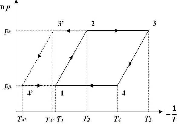
The typical structure of the adsorptive refrigeration system with a single bed consists of the following elements: an evaporator, one adsorber bed, a condenser, and a throttling valve (Fig. 1). This kind of system is powered by thermal energy which generates the cyclical heat receiving process in the evaporator. The work cycle of this type of refrigeration system is comprised of four phases: the adsorbent bed heating phase, the bed regeneration (desorption), the adsorbent bed cooling phase, and the adsorbate adsorption. Furthermore, the periodic run of individual phases in the Clapeyron diagram is shown (Fig. 2). During the first phase (1-2), the adsorbent bed is heated in the isochoric process causing the pressure and temperature to increase simultaneously. When the pressure reaches the value ps at the Point 2, then the desorption process takes place. During the
and desorption is carried out at that time. The end of this phase occurs after reaching Point 3, when the adsorbent bed is completely regenerated. The next stage of the process is the 3-4 phase, when heat is given back.
Figure 1. Block diagram of a single bed adsorption refrigeration system.
During this phase, which is the isochoric cooling of a single bed, a decrease in temperature and pressure occurs. At the moment of the pp pressure of adsorbate
evaporation, when Point 4 is reached, the adsorption process starts on the surface of the adsorbent bed. This process is performed during the 4-1 phase while heat is received from the system. At Point 2, when the desorption process in a single adsorber bed is started in parallel, evaporated refrigerant flows from the adsorber bed to the condenser (Point 3'). Under the 3'-4' step, condensation of the refrigerant in the condenser happens.
[image:3.612.152.451.441.645.2]In a further stage, the liquid phase of the adsorbate via the throttling valve into the evaporator space is dosed (Point 4'). In the evaporator space, the evaporation of the refrigerant takes place whose steam goes to the adsorber bed, where it is re-adsorbed. Moreover, evaporation of the adsorbate in the evaporator causes a decrease of the temperature in the evaporator space under the influence of receiving heat. As a result, a cooling effect in the adsorption refrigeration system is created.
2. THE BASIC PRINCIPLES OF ENERGY TRANSFER IN A SINGLE BED
The above adsorption refrigeration device is powered by thermal energy, which is supplied to the system. Furthermore, the total thermal energy, Qha,
provided to the system comes into a single bed of the adsorber for its heating (Fig. 1). The presented graph (Fig. 2) of the ideal cycle of the adsorption heat exchange shows that the total thermal energy Qha supplied to the system is equal to the sum
of energy Q1-2 and energy Q2-3 [11,12]. Whereas, the Q1-2 is the energy required to
increase the adsorbent temperature of a single bed and the adsorbate (from Point 1
to Point 2). On the other hand, the Q2-3 is the energy needed to continue the
heating and desorption process of the adsorbate (from Points 2 to 3). The energies can be calculated using the following relations:
3 2 2 1
Q Q
Qha , (1)
1
2 1
2
1 mCp m Cp T T
Q s s w w
, (2)
msCps Cpw mw mw
T T
mw mw HawQ23 [( 1 3)/2] 3 2 ( 1 3)
, (3)
where:
ms—mass of a single bed of the adsorbent, kg;
mw1, mw3—adsorbate mass, kg, (1,3—the points on the Clapeyron diagram
(Fig. 2));
T1, T2, T3—temperature, K, (1,2,3—the points on the Clapeyron diagram (Fig. 2));
Cps—specific heat of the adsorbent, kJ/kgK;
Cpw—specific heat of the adsorbate, kJ/kgK;
Haw—heat adsorption of the adsorbate, kJ/kg;
A calculation of the entire evaporative energy of the adsorbate (Qp) generated
in the heat receiving process in the evaporator is shown below:
w w
pwp m m H
Q 1 3 , (4)
where:
Hpw is the heat of the evaporation of the adsorbate, kJ/kg.
The total Qsk energy dissipated as a result of the refrigerant condensation in
the condenser is represented as follows:
m 1 m 3
Cp T3' T4'
Qsk w w w
, (5)
where:
T3’, T4’—temperature, K, (3’,4’—the points on the Clapeyron diagram (Fig. 2)).
Performance of an adsorption refrigeration cycle for an adsorber with a single bed, defined as the Coefficient of the Performance (COP), is calculated by the following equation:
ha p
Q Q
COP (6)
3. CASE STUDY OF ADSORPTION SYSTEMS WITH A SINGLE BED
3.1. Adsorptive Ice Makers with a Cylindrical Adsorber
by natural convection. The next element of the system is the condenser. It is constructed by eight parallel finned tubes, which are air-cooled as well as through natural convection. Moreover, the total heat transfer surface of the finned condenser is 6.9 m2. The next component of the system is the evaporator, which is made from square pipe in the form of three rings. Furthermore, the entire area of heat exchange in it is 3.4 m2. The evaporator is placed in an insulated chamber with a volume of 320 l, and the evaporator contains 40 litres of water, which is converted into ice.
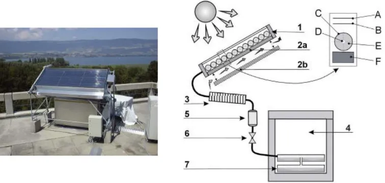
Figure 3. View and draft of adsorptive solar refrigerator: 1-solar collector-adsorber with detail: A-glass cover, B-Teflon film, C-tube covered with selective surface and internally layered
with Papyex, D-central tube for vapour transport, E-silicagel bed, F-thermal insulation around the collector; 2-ventilation dampers: 2a-closed and 2b-open; 3-condenser; 4-cold cabinet; 5-graduated tank; 6-check valve; 7-evaporator and ice storage [13].
In the presented system, after performing numerous verification tests and improvements, a COP from 0.10 to 0.25 was obtained. The distinguishing features of the presented solution are the following: simple construction, the possibility of using solar thermal energy, utilizing ecological substances as the adsorbent-adsorbate pair, and dispensing refrigerant from the graduated tank. The challenges of the system are cyclical operation and the low value of the coefficient of the performance.
an adsorbent bed located in the adsorber, condenser, and evaporator. The adsorbent bed is placed in a flat glass circular container with a diameter of 20 cm and a thickness of 5 cm. The thickness of the cylindrical glass of the bed is 3 mm. The amount of charcoal grains found in the deposit is 0.6 kg, and the weight of the small pieces of steel is 0.2 kg. The next element of the system, the condenser, is constructed of a glass tube with a 15 mm diameter and a 50 cm length. Another component of the device is the evaporator, which is designed in a shape of a cylinder with a 5 cm diameter and is also made of glass, and it contains 0.2 kg of methanol. The operation of the presented solution consists of adsorption and desorption of methanol by the adsorbent bed. During the day, the adsorbent bed is heated by the solar radiation, and the evaporated adsorbate flows to the condenser. In order to condense the evaporated refrigerant in the condenser, the refrigerant in the liquid phase then runs to the evaporator where it is stored. During the night, since there is no supply by the solar energy, the adsorbent bed is cooled through natural convection of the ambient air.
[image:7.612.117.477.319.515.2]
Figure 4. Photograph and scheme of the adsorption refrigeration system with adsorber in a form of flat cylindrical container [12].
to 0.159. The presented solution is characterized by the possibility of utilizing solar energy, simple construction, and the use of ecological substances as the working pair. An unfavourable aspect of the system is storing the liquid refrigerant directly in the evaporator, since it can evaporate in an uncontrolled way. Other unfavourable aspects include the low value of the coefficient of the performance and the periodical work of the device.
3.2. Adsorption Refrigeration System for Air Conditioning with Energy Storage
[image:8.612.118.473.500.636.2]A different solution using the adsorption refrigeration system with a single bed is a device for the storage of thermal energy in the adsorbent bed. This device is utilized for the heat receiving in the evaporator (generating cold), in this way, air cooling is realized in a connected room. Moreover, the received thermal energy can be directly transferred to this room as well (Fig. 5). The system is dedicated to the cyclical storage of thermal energy from hot exhaust gas of a combustion engine during the daytime and cold generation from the stored heat during the night. The presented solution consists of the two main components: the adsorber and the evaporator/condenser as one element. Furthermore, in this system, 13XBF zeolite and water is exploited as an adsorbent-adsorbate pair. A single bed is placed inside a finned copper adsorber, which consists of an inner and outer layer, and it is in the shape of a rectangle. The construction of the finned copper adsorber has its benefits, i.e. better heat transfer to the bed. However, this effect is a weak spot of the solution, because it prevents maintaining a low temperature in the bed. Moreover, the internal volume of the adsorber in which the bed is located is 35 l. The second main component of the system is the evaporator/condenser as one unit, which contains a vessel for a refrigerant.
This element plays the role of the condenser and a refrigerant storage place in the liquid phase during the desorption process. When hot exhaust gas flows by the adsorber, heat transfer to the bed occurs. During this time, the desorption process takes place and thermal energy storage in the adsorbent bed happens. When the desorption process stops and the adsorption starts, the component of the system changes its function from the condenser to the evaporator. Afterwards, the refrigerant stored in the liquid phase evaporates and generates cooling in the evaporator space. During the adsorption process, ambient air flows through the evaporator where is cooled down and flows into the room to be cooled. An additional component of the system is the main valve connecting the adsorber and the unit of the evaporator/condenser. It works periodically by its cyclic opening and closing. Values of the main parameters of the work of the system are as follows:
The minimum pressure in the adsorber is 0.1 –10 Pa.
The maximum temperature of exhaust gas that flows throughout the adsorber is under 300°C.
12–20 °C is the air temperature in a cooled room.
The entire amount of stored energy for several hours of cooling is 3 kWh.
20–100 mbar is the range of pressure change during the desorption process in the adsorber and the condenser.
24–40 C is the temperature in the condenser.
The pressure change during the adsorption process in the evaporator is
10–24 mbar when the temperature in the evaporator is below 20°C.
The interesting features of this system are the possibility of utilizing energy from the heat of exhaust waste gas, using the adsorbent bed as an innovative thermal energy store and applying ecological substances as the adsorbent-adsorbate pair. Furthermore, in the solution, there are some aspects to take into consideration, such as the following: using medium-temperature sources as heat sources, a complicated construction of the device, cyclical operation of the system, and the lack of possibility of long-term maintenance of the low temperature in the adsorbent bed.
3.3. Adsorption System for Heat Receiving and Ambient Air Warming
adsorber is 110 ml, and it is filled with the adsorbent in the form of a
CaClBr/SiO2 composite (a grain size of 0.2–0.5 mm and a mass of 700 g). The
[image:10.612.105.494.187.318.2]next component of the system is the evaporator/condenser, which is built as a single exchanger, which is the same as mentioned above. In this unit, the refrigerant is stored in the liquid phase.
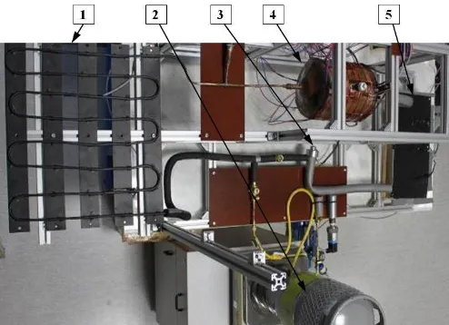
Figure 6. Photography and diagram of the adsorption system for air heating; 1—adsorber; 2—condenser/evaporator; 3—thermocryostats; 4—vacuum pump;
F1-F3—flowmeters; V0—vacuum valve; V1-V8—valves; P-pressure gauge [15].
condenser of low pressure in the range of 10–100 mbar. The presented solution allows the generation of the maximum heating power at the level of 1.0–2.5 kW
with the temperature of the released heat in the range of 32 to 49°C. A fascinating property of this solution is the innovative application of the adsorption system for the generation of thermal energy using low and very low-temperature heat sources with extreme temperatures from -60°C to 30°C. Furthermore, the challenges of the prototype can be cyclic work, the complexity of the structure, the necessity of mechanical switching of the individual circulations to trigger another sorption process, and no refrigerant container.
3.4. The Author Adsorption Refrigeration System
[image:11.612.181.428.403.582.2]The major components of the developed proprietary adsorption refrigeration system are the following: adsorber, condenser, throttling valve, and evaporator (Fig. 7). In the prototype, there is a single adsorbent bed which is placed in the adsorber, where the adsorption and desorption process alternate runs. In the device, silica gel and water is exploited as the adsorbent-adsorbate pair, and the amount of silica gel loaded is 4.85 kg. The adsorber is made of copper in the shape of a cylinder. The condenser is built of copper tubes connected with single flat elements performed with a copper sheet. The adsorber is made of copper in the shape of a cylinder.
Figure 7. View of the model adsorption refrigeration system; 1—condenser; 2—refrigerant tank; 3—expansion valve; 4—adsorber; 5—evaporator.
The condenser is built of copper tubes connected with single flat elements formed from copper sheets. A commercial electronic expansion valve (LNE type,
evaporator which is made in the form of a copper plate with copper tubes attached. The system works by forcing the desorption process on the adsorbent bed, and heating the adsorber to a temperature of 70–100°C. As a result, the evaporated adsorbate passes to the condenser, where the condensation of it takes place. Afterwards, the refrigerant is storage in its tank. From the reservoir, the refrigerant is dosed into the evaporator space via the expansion valve. Evaporated refrigerant in the evaporator flows to the single bed of the adsorbent where it is adsorbed. The evaporation process of the refrigerant in the evaporator causes heat receiving, which results in many hours of temperature drop in the evaporator. The decrease is to the average minimum temperature of 11°C [16]. As an effect of the multi-day investigations of the device, the average value of the coefficient of the performance is 0.44.
CONCLUSIONS
The analysis shows that the great benefit of the adsorption refrigeration systems is the prospect of their utilization for various applications. In the article, solutions used for ice production, the storage of thermal energy and its use in air-conditioning systems and useful thermal energy generation are presented. The author’s solution that can be applied in both air-conditioning systems and ice-maker devices is also described. Other examples of applications of the adsorption refrigeration systems are the following: adsorption chillers [17], sorption heat pumps [18], trigeneration systems [19], and desalination systems [20].
development of the adsorption systems. This action can be carry on through the following: the development of substances used for the adsorbent-adsorbate pair; improvement of the adsorber construction (as cylindrical, flat or with a complex shape); ameliorating and lengthening the time of refrigerant dosing to the evaporator working space; the development of the construction and operation of the condenser; and, the improvement of other components of this type of systems, e.g., shut-off valves, expansion valves, reservoirs, and an appropriate location of these subsystems in the installation.
The tendency of investigations of the adsorption refrigeration systems is currently focused on the following issues: increasing the coefficient of the performance, the constructing of systems with a minor cubature, and improving reliability. Furthermore, there should be design solutions that guarantee more effective cooling and heating of the adsorbent, which can be supported by applying modern technologies, such as infrared thermography [22] or innovative coatings of heat exchange elements [23, 24].
REFERENCES
1. Communication from the commission to the European parliament, the council, the European economic and social committee and the committee of the regions. An EU Strategy on Heating and Cooling, Brussel, 2016. Available from: https://ec.europa.eu/energy/sites/ener/files/ documents/1_EN_ACT_part1_v14.pdf [Accessed 15 April 2019].
2. Alam K.C.A., A. Akahira, Y. Hamamoto, A. Akisawa, and T. Kashiwagi. 2014. “A four-bed mass recovery adsorption refrigeration cycle driven by low temperature waste/renewable heat source”, Renewable Energy, 29: 1461–1475.
3. Zarzycki R. 2016. “Wykorzystanie ciepła odpadowego z układu sprężania CO2 do produkcji wody lodowej”, Zeszyty Naukowe Instytutu Gospodarki Surowcami Mineralnymi i Energią
Polskiej Akademii Nauk, 95: 169–180.
4. Oliveira R. G. 2011. Solar powered sorption refrigeration and air conditioning.
Refrigeration: Theory, Technology and Applications. Nova Science Publishers, Inc.,
chapter 4, pp. 205–238.
5. Wang L.W., R. Z. Wang, and R. G. Oliveira. 2009. “A review on adsorption working pairs for refrigeration”, Renewable and Sustainable Energy Reviews, 13(3): 518–534.
6. Mohammed R. H., O. Mesalhy, M. L. Elsayed, and E. M. L. Chow. 2019. “Assessment of numerical models in the evaluation of adsorption cooling system performance”, International
Journal of Refrigeration, 99: 166–175.
7. Ramji H. R., S. L. Leo, I. A. W. Tan, and M. O. Abdullah. 2014. “Comparative study of three different adsorbent-adsorbate working pairs for a waste heat driven adsorption air conditioning system based on simulation”, IJRRAS, 18(2): 109–121.
8. Hamed A. M., W. R. Abd El Rahman, and S. H. El-Emam. 2010. “Experimental study of the transient adsorption/desorption characteristics of silica gel particles in fluidized bed”, Energy, 35(6): 2468–2483.
9. Wu W.-D., H. Zhang, and D.-W. Sun. 2009. “Mathematical simulation and experimental study of a modified zeolite 13X–water adsorption refrigeration module”, Applied Thermal
10. Sumathy K., K. H. Yeung, and L. Yong. 2003. “Technology development in the solar adsorption refrigeration systems”, Progress in Energy and Combustion Science, 29(4): 301– 327.
11. Ambarita H. and H. Kawai. 2016. “Experimental study on solar-powered adsorption refrigeration cycle with activated alumina and activated carbon as adsorbent”, Case Studies in
Thermal Engineering, 7: 36–46.
12. Khattab N.M. 2004. “A novel solar-powered adsorption refrigeration module”, Applied
Thermal Engineering, 24: 2747–2760.
13. Hildbrand C., P. Dind, M. Pons, and F. Buchter. 2004. “A new solar powered adsorption refrigerator with high performance”, Solar Energy, 77: 311–318.
14. Semprini S., S. Asenbeck, H. Kerskes, and H. Druck. 2017. “Experimental and numerical investigations of an adsorption water zeolite heat storage for refrigeration applications”.
Energy Procedia, 135: 513–521.
15. Tokarev M. M., L. G. Gordeeva, A. D. Grekova, and Y. I. Aristov. 2018. “Adsorption cycle “heat from cold” for upgrading the ambient heat: The testing a lab-scale prototype with the composite sorbent CaClBr/silica”, Applied Energy, 211: 136–145.
16. Neska M. and A. Majcher. 2018. “Koncepcja sterowania adsorpcyjnego układu chłodniczego małej mocy”, in Możliwości i horyzonty ekoinnowacyjności. Zielona Energia, D. Całus, K. Oźga, T. Popławski, A. Michalski, and K. Szczepański, eds. Cżestochowa: Wyd. Politechniki Częstochowskiej, pp. 141–153.
17. Szyc M. and W. Nowak. 2014. “Operation of an adsorption chiller in different cycle time conditions”, Chemical and Process Engineering, 35(1): 109–119.
18. Miles D. J. and S. V. Shelton. 1996. “Design and testing of a solid-sorption heat-pump system”, Applied Thermal Engineering, 16(5): 389–394.
19. Gazda W. and W. Stanek. 2016. “Energy and environmental assessment of integrated biogas trigeneration and photovoltaic plant as more sustainable industrial system”, Applied Energy, 169: 138–149.
20. Mitra S., K. Thu, B. B. Saha, and P. Dutta. 2017. “Performance evaluation and determination of minimum desorption temperature of a two-stage air cooled silica gel/water adsorption system”, Applied Energy, 206: 507–518.
21. Gwadera M. and K. Kupiec. 2011. “Adsorpcyjne układy chłodnicze”, Inż. Ap. Chem, 50(5): 38–39.
22. Dudzik S. 2011. “Investigations of a heat exchanger using infrared thermography and artificial neural networks”, Sensors and Actuators A: Physical, 166: 149–156.
23. Kucharczyk W., P. Przybyłek, and T. A. Opara. 2013. “Investigation of the thermal protection ablative properties of thermosetting composites with powder fillers: the corundum Al2O3 and the Carbon Powder C”, Polish Journal of Chemical Technology, 15(4): 49–53.
![Figure 4. Photograph and scheme of the adsorption refrigeration system with adsorber in a form of flat cylindrical container [12]](https://thumb-us.123doks.com/thumbv2/123dok_us/245330.1024393/7.612.117.477.319.515/figure-photograph-scheme-adsorption-refrigeration-adsorber-cylindrical-container.webp)
![Figure 5. View and diagram of the adsorption refrigeration setup for air conditioning with energy storage [14]](https://thumb-us.123doks.com/thumbv2/123dok_us/245330.1024393/8.612.118.473.500.636/figure-view-diagram-adsorption-refrigeration-conditioning-energy-storage.webp)
![Figure 6. Photography and diagram of the adsorption system for air heating; 1—adsorber; 2—condenser/evaporator; 3—thermocryostats; 4—vacuum pump; F1-F3—flowmeters; V0—vacuum valve; V1-V8—valves; P-pressure gauge [15]](https://thumb-us.123doks.com/thumbv2/123dok_us/245330.1024393/10.612.105.494.187.318/photography-adsorption-adsorber-condenser-evaporator-thermocryostats-flowmeters-pressure.webp)