2019 International Conference on Applied Mathematics, Modeling, Simulation and Optimization (AMMSO 2019) ISBN: 978-1-60595-631-2
Modeling and Analysis of Helmholtz Cavity Basing on One-dimensional
Plane Wave Propagation
Zhen LI and Yong CHEN
*College of Aerospace Science and Engineering, National University of Defense Technology, Changsha, China
*Corresponding author
Keywords: Helmholtz resonance, Volumetric measurement, One-dimensional plane wave model.
Abstract. Propellant volumetric measurement based on the tank cavity resonant dynamics may be a promising alternate for satellite to improve its performance. The tank could be modeled as ‘Helmholtz resonator’, and volume of the cavity can be calculated from the resonant frequency according to the theoretical formula. Unlike the traditional Helmholtz resonation modelling, where cavity is taken as an ideal acoustic component, this paper gives mathematical modelling based on one-dimensional plane wave approximation, with compressibility of liquid being concerned. Comparisons with simulated and experimental results validate the present model. Good consistency could be found between theoretical and numerical results. Meanwhile, they are slightly larger than the experimental results. Results prove that present model can accurately predict the resonance resonant frequency of the tank, which may be used in the propellant volumetric measurement.
Introduction
High-accuracy volumetric measurement is important for satellite to improve its performance, which means making full use of resources and increasing effective load. There have been several methods to satisfy the measurement requirement according to literature, such as PVT (Pressure, Volume, Temperature), PGS (Thermal Propellant Gauging) and BK (Book-Keeping) method. Problems of above three methods are considered by Yendler[1], which shows that errors generate due to nonideal gas in PVT method and accumulate with time in BK method. Meanwhile, accuracy of PGS method is inversely proportional to the propellant fill level. Compared to these traditional methods, cavity-resonance measurement, which is based on Helmholtz resonance, may be a possible alternate for volumetric measurement. Corresponding ground experiment by Webster[2] shows that the measurement accuracy is better than ±0.1% of the resonator’s volume (3L) and the repeatability is generally ±1ml.
rigid wall. However, compressibility of the propellant may also affect the cavity resonance and will result in performance reduction of volumetric measurement.
This paper therefore theoretically models the resonator based on a one-dimensional wave approximation, with compressible liquid being concerned. Theoretical formula is given by solving the corresponding determinant problem of the coefficient matrix. Results of present model are compared with the numerical simulations and experimental data. The structure of this paper is as follows. Section 2 gives a basic model under the assumption that the propellant is compressible. Section 3 compares theoretical predictions with numerical simulation, experimental results. Section 4 concludes the work presented in this paper.
Theoretical Modeling
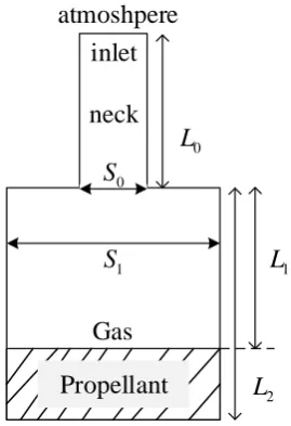
Geometry of tank is shown in Figure 1, with the neck and cavity is modeled as cylinder. The tank consists of three main parts, namely the opening neck, the gas segment and the propellant segment, meanwhile the inlet of neck opens to external atmosphere. The cross-sectional area of neck and cavity are S0, S1 respectively, with corresponding length being L0, L2. Length of gas segment is L1.
0
L
2
L
1
L
Propellant Gas neck inlet atmoshpere
0
S
1
[image:2.595.243.378.300.497.2]S
Figure 1. Geometry of tank with opening neck connected with atmosphere.
There is assumption that the wavelength of acoustic is far larger than diameter of cavity so that wave propagates only along axial direction. Another important hypothesis is linearization. Any quantityF in this paper is decomposed as F F F, where F is the base part and F is the fluctuating part. Effects of viscous dissipation and thermal conduction are neglected, meanwhile gas is assumed as ideal. Then we have the model based on one-dimensional plane wave approximation as shown in Figure 2. Subscripts like ‘0’, ‘1’, ‘2’, ‘n’ are used to represent variables in the neck, gas, propellant and arbitrary segment.
x 1
xL u p
R
d o w n
R
2
x L 0
x
0
n n1 n2
+
-, , ,
n n n n
p v T
bottom
0
x L
gas-propellant interface
0
S S1
inlet
[image:2.595.131.473.645.769.2]The base part in the tank is stationary, then we reach the following constraints for the base flow
0 1 2, 0 1 2, 0 1 2 0, 0 1.
p p p T T T v v v (1) With ,p,T,v represent density, pressure, temperature and velocity respectively.
The acoustic disturbance could be considered as superposition of waves propagating upstream (denoted by ‘-’) and downstream (denoted by ‘+’). As the plane wave is considered, the perturbations in time domain(denoted by superscript ‘ ’ ) could be expressed by perturbations in frequency domains(denoted by superscript ‘ ^ ’ )
, ˆ exp i
,
, ˆ exp i
n n n n n n
p x t p tx c p x t p tx c (2) Disturbances of the acoustic velocity could get according to the pressure
1 p v dt x
(3)Combing Eq. (2) with (3), the disturbances of the acoustic pressure and velocity could be expressed by pressure perturbations downstream and upstream
ˆ ˆ T ˆ ˆ T
n n n n n
v x p x x p p
B (4)
With
1 i 1 i
exp exp
i i
exp exp
n n n n n n
n
n n
x x
c c c c
x x x c c
B (5)
At the zero location x0, there is a sudden change of cross section with area ratio (C1/C0). Noting
that the Mach number is zero, and there is no heat input to system, the velocity jump relation in terms of volumetric flow rate could be expressed as [7, 8]
0 0 1 1, 0 1.
C vC v p p (6)
Then we have the following expression
0 0 1 1 0 1 0 1 ˆ ˆ
(0) (0) (0) , (0) .
ˆ ˆ 1 C p p C p p
A B B 0 A (7)
There is same relation like Eq. (6) at liquid-gas boundary xL1, with cross section is unity
0 1 1 1 , 0 1 1 1 .
v L v L p L p L (8)
Similar to Eq. (7), at the location xL1, we have
1
1 1 11
2 1
2 1
2 1
ˆ ˆ 1
( ) ( ) ( ) , ( ) .
ˆ L L L ˆ L 1
p p p p
B A B A (9)
The acoustic reflections at the inlet (x L0) and bottom (xL2) should be considered. By
introducing reflection coefficients ( up
R and down
R ), we have the boundary conditions
0
up up up
0 0 0 0 0 0
0 ˆ
0, exp i / exp i / .
ˆ
p
L L L c R L c
p
2
down down down
2 2 2 2 2 2
2 ˆ
0, exp i / exp i / .
ˆ
p
L L R L c L c
p
F F (11)
Inserting Eq. (11) and (9) yields
1
1 11 1
down
2 2 1
1 ˆ ( ) ( ) ( ) 0.
ˆ
L L L p
L p
F B A B (12)
Combining Eqs. (7), (10)and (12) gives the model which considers the compressibility of the propellant, written in matrix form
4 4 0, ˆ0 , ˆ0 , ˆ1 , ˆ1 . T
p p p p
G X X (13)
With
1
1 1up
0 1 2
4 4 0 1
1 down
1 2 2 2 1
(0) (0) (0)
( )L ( )L ( )L
L L F 0
G A B B
0 F B A B
(14)
To get the resonance frequency, it means the matrix has a non-zero solution, leading to the vanishing of the determinant det
G4 4
0Simulation and Validation
The validity of proposed model is demenstrated by comparing resonant frequency of theoretical calculation with numerical simulations and experimental results by Webster[2]. Corresponding experimental configurations are shown in Figure 1 with the neck’s length and diameter being 170mm
and 44mmrespectively. The length and diameter of the cylindrical cavity are 190mm and 141.8mm. Water is used to represent propellant. The gas and liquid density are 3
1.29kg/m and 3
1000kg/m , corresponding sound speed are c0 c1 343m/s and c21500m/s.
At the bottom (xL2), fully reflection leads to the rigid boundary condition, withRdown1. At the
inlet of the tank, the pressure disturbance will not vanish immediately, but propagate to the infinity where the pressure disturbance reduces to zero. According to literature contributions, end correction
i
is introduced to model such effect. The neck length therefore changes to
0 0 i
*
L L (15) Where pressure disturbance vanishes at the inlet up
1
R . Ingard[6] gave a theoretical prediction of
the end correction with
1/2 i= 8 / 3 (C0/ ) . When L1 is determined, resonant frequency of present
model could be given by calculating the determinant of Eq. (14). It should be noticed that classical model introduce another end correction o for outlet that opens into cavity, called o. In present
model, the correction length i should be introduced in the present model to accept the scattering at the inlet of the opening neck, but o is not required as the perturbation dynamics in cavity has been
modeled.
Numerical simulations are implemented by COMSOL. In the numerical simulations, the configurations keep consistent with experimental rig. To consider the end correction, we impose a large sphere around the model, with the diameter being extremely larger than that of the neck, to represent the external environment. Pulse vibration is used to excite the resonance frequency of the system to mimic the flow-excited noise generations[9]. Two fixed point is chosen, with one as acoustic source meanwhile another point is used for recording the pressure perturbation. The spectrum peak is obviously the resonate frequency of resonator.
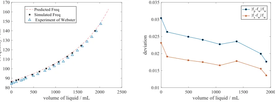
Results in Figure 3a shows that the resonant frequency becomes larger along with the increase of the water filling level. Good consistency could be found between the present model and numerical simulation, while the experimental results seem a little lower than the theoretical and numerical predictions.
Specifically, We define deviations as fp fw / fw and fs fw / fw, where fp, fs and fw are
[image:5.595.74.518.297.462.2]the resonant frequencies, obtained from theoretical calculation. numerical simulations and experimental results conducted by Webster respectively. Figure 3b plot the deviations of the theoretical predictions and experiment, numerical simulations and experiment. Obviously, Figure 3b shows that both of two deviations decrease when the water fills the cavity. A possible reason is that the value of fraction is inversely proportional to that of the denominator, which is the growing experimental results fw. Meanwhile, deviations of the theoretical predictions and experiment are slightly larger than deviations of numerical simulations and experiment. Besides, the close lines of deviation show good consistency between theoretical and numerical results. Results shown in Figure 3 prove the theoretical model based on one-dimensional plane wave propagation well predicts resonant frequency of Helmholtz resonator with compressibility of liquid being considered.
Figure 3. Resonant frequencies obtained from theoretical prediction, numerical simulation and experimental test under different water filling level. a. resonant frequencies for different water filling level. b. the changing deviation
for different water filling level.
Conclusions
This paper theoretically models Helmholtz resonator based on the one-dimensional plane wave approximation, with compressibility of liquid being considered. Predicted resonant frequency by the present model is compared with numerical simulation and experimental results. Good consistency can be found among the present model and numerical simulation, while the experimental results seem a little lower than the theoretical and numerical predictions. Results prove that one-dimensional model can accurately predict the resonance resonant frequency of the tank, which may be used in the propellant volumetric measurement.
References
[1] D.B. Yendler, Review of Propellant Gauging Methods, in: 44th AIAA Aerospace Sciences Meeting and Exhibit, 2006.
[2] E.S. Webster, C.E. Davies, The use of Helmholtz resonance for measuring the volume of liquids and solids, Sensors, 10 (2010) 10663-10672.
[4] R.C. Chanaud, Effects Of Geometry On The Resonance Frequency Of Helmholtz Resonators, Journal of Sound and Vibration, 178 (1994) 337-348.
[5] M. Alster, Improved calculation of resonant frequencies of Helmholtz resonators, Journal of Sound and Vibration, 24 (1972) 63-85.
[6] U. Ingard, On the theory and design of acoustic resonators, The Journal of the acoustical society of America, 25 (1953) 1037-1061.
[7] E. Courtine, L. Selle, T. Poinsot, DNS of Intrinsic ThermoAcoustic modes in laminar premixed flames, Combustion and Flame, 162 (2015) 4331-4341.
[8] M. Bauerheim, F. Nicoud, T. Poinsot, Theoretical analysis of the mass balance equation through a flame at zero and non-zero Mach numbers, Combustion and Flame, 162 (2015) 60-67.