2019 2nd International Conference on Informatics, Control and Automation (ICA 2019) ISBN: 978-1-60595-637-4
Analysis and Optimization of Milling Process for Crankshaft Pin
Based on Energy Consumption
Hui-ling LI
*, Min LUO, Zhi-chu CHEN, Jin-yu XU and Ling-yun LIU
Hubei University of Automotive Technology, Hubei Shiyan 442002, P.R. China
*Corresponding author
Keywords: Green manufacturing, Cutting process optimization, Analysis of energy consumption of CNC machine tools, CNC machine tool power acquisition & monitoring platform, Inner milling process of crankshaft pin.
Abstract. A power acquisition & monitoring platform is set up based on RS485 bus, with all the
power data of CKM200 milling machine tool during the crankshaft pin processing is collected and monitored in real time. The crankshaft inner milling process is analyzed from the perspective of energy consumption. Under the premise of not changing the process parameters, the crankshaft inner milling process optimization is carried out, the unnecessary movement is removed or optimized. As a result, the corresponding subsystem consumption is reduced, and the goal of reducing the total energy consumption of CKM200 crankshaft inner milling machine is achieved. It provides a reference for realizing green manufacturing.
Introduction
CNC machine tools are widely used in the machining process of the automotive industry, with enormous total amount of energy consumption. Therefore, research on energy characteristics and energy consumption in CNC machining is of great importance. In this paper, a power acquisition and monitoring platform is built, collecting the input power data of the two spindle motors and whole machine tools of the CKM200 crankshaft inner miller during its machining processing of the crankshaft pin, and the inner milling processing is analyzed from the perspective of energy consumption. These analysis and optimization may help to realize green manufacturing.
CKM200 Crankshaft Pin Milling Processing Analysis
Fixed Chuck Mobile Chuck
Cutter Head1
Cutter Head2 Gantry1 Gantry2
Center Frame1
Center Frame2
X1 X2
Y1 Y2
[image:2.595.93.501.71.334.2]Z1 Z2
Figure 1. Schematic diagram of CKM200 crankshaft inner milling machine.
Chuck Clamper
Tip
#1
#2 #3
#4
Chuck
[image:2.595.184.408.75.181.2]Clamper Tip
Figure 2. Schematic diagram of the four –cylinder engine ZD30 crankshaft.
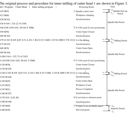
The original process and procedure for inner milling of cutter head 1 are shown in Figure 3.
NC1 Program( Cutter Head 1 Inner milling program ) Processing Route Time
N10 M03; ①Spindle (cutter) start
N15 M68; Workpiece clamping
N20 M 101; Synchronization
N30 # 164=- 216. 22+# 2104;
N40 G 90 G 94 G 01 Z# 164 F 2000; ②# 4 Pin axial (Z-axis) positioning
N50 M58; Center frame Closure
N60 M 102;
N70 G 102 R 105 Q 29 S 51 A 101. 5 B6 E 19. 5 I 680 J 225 K 2000 C 270D 4;③# 4 Pin Milling
N75 M 103;
N80 M59; Center frame Open
N90 M 104;
N 100 # 163=- 322. 72+# 2103;
N 110 G 90 G 94 G 01 Z# 163 F 2000; ④# 3
N 120 M58; N 130 M 105;
N 140 G 102 R 105 Q 29 S 51 A 101. 5 B6 E 19. 5 I 680 J 225 K 2000 C90D 3;⑤# 3
N 145 M 106; N 150 M59;
N 152 M22; Workpiece Count
N 155 M21; Process Completed
N 160 M 107;
N 170 G 91 G 28 Z0; ⑥Z axis back to reference point
N 180 M 108;
N 190 M69; ⑦
N 200 M30; End of program
Spindle Start-up Period
Spindle Idle Period
Milling Period
Stand-by Period
s t
t
0 1
t
C1
t
03
t
S
t
02
t
C2
t 0
Spindle Idle Period
Spindle Idle Period Milling Period Synchronization
Synchronization
Synchronization
Pin axial (Z-axis) positioning
Center frame Closure
Synchronization
Pin Milling
Synchronization
Center frame Open
Synchronization
Synchronization
Workpiece loosen and Spindle stopped
[image:2.595.72.512.355.742.2]CKM200 Inner Milling Processing Power Data Acquisition and Power Curve Analysis
The crankshaft CNC machine tool power acquisition & monitoring platform uses the three-phase electric parameter collector to obtain the digital signal, and RS485 bus communication method to transmit the data to the King view host computer and store it in the SQL Server database in real time. The three-phase electric parameter collector adopts WB6830R2-P electronic energy collecting module .The electric current transformers are installed on the three-phase inlet lines of CNC machine tool and the two spindle motor inlet lines, and are connected to the input ends of the power collection modules. The output of the power collection module is connected with the data-server PC by means of RS485 ~ USB conversion module. The structure and hardware connection of the power acquisition and monitoring platform of the crankshaft CNC machine tool are shown in Figure 4.
R
S
48
5~
U
S
B
E
le
ct
ri
c
le
ve
l
co
nv
er
si
on
m
od
ul
e
DATA+ DATA-+Us GND
+24V
+E +E G G A A B B
+E +E G G A A B B G G A A B B
N C B A Ic2
Ib2
WB6830R2-P Electric energy collecting module2
Ia2
UaUbUnUc Ic1
Ib1
WB6830R2-P Electric energy collecting module1
Ia1
Ia+ Ia- Ib+ Ib- Ic+ Ic -UaUbUnUc
Ic3
Ib3
WB6830R2-P Electric energy collecting module3
Ia3
UaUbUnUc *
* *
* * * * *
* Kin
gview Software
Machine tool total power acquisition
+E +E
Ia+ Ia- Ib+ Ib- Ic+ Ic- Ia+ Ia- Ib+ Ib- Ic+ Ic
-Spindle motor1 power acquisition
Host computer
[image:3.595.75.522.224.373.2]Spindle motor2 power acquisition
Figure 4. Crankshaft CNC machine tool power acquisition & monitoring platform structure and hardware connection.
The input power data of the machine tool and the two spindle motors during the inner milling process of the four-cylinder engine ZD30 crankshaft blank pin are collected, and arbitrarily intercepted data of one machining cycle. Using professional data graphics & analysis software OriginPro 8, data were analyzed to obtain CKM200 crankshaft processing power curve as Figure 5. According to the different characteristics, the power curve is divided into the spindle start-up period, the spindle idle period, the milling period and the standby period. The energy consumption calculated for one processing cycle is as shown in Equation 1.
1
0 1538030
T
[image:3.595.67.533.512.770.2]Optimization of Processing Technology Based on Energy Consumption
The original processing program has been applied to actual production for many years, and the processing parameters selection is reasonable, which can ensure the high quality and high efficiency of the production, so it remains unchanged.
Under the premise that processing parametersap, ft, ae, D, n, N and vC are kept constant and
workpiece material and cutting conditions remains unchanged, then the following can be obtained. 1. The duration of the spindle start-up period, the spindle idle period, the milling period and the
standby period remain unchanged, i.e., the durations of the seven processing stages Phase ①, Phase
②, Phase ③, Phase ④, Phase ⑤, Phase ⑥, Phase ⑦, seven stages of processing are invariant. 2. When the spindle is unloaded and milling power is 0, main drive system input powerPM10,
20 M
P is equal to main drive system no-load lossp01,p02, feed drive system input powerPF0 which
equals the no-load power p0F of the feed drive system, and auxiliary system powerPAUX are all constant losses [3].
3. During milling, main drive system input powerPM1 andPM2 remains constant; feed drive system input powerPF and auxiliary system powerPAUX are unchanged as well.
4. Spindle start-up period (Phase ①) machine input power remains constant as Eq. 2.
AUX Mst
st P P
P1 . (2)
5. Spindle no-load period (Phase②, ④, ⑥) machine input power remains constant as Eq. 3.
AUX F AUX
F M
M P P P p p p P
P
P10 10 20 0 01 02 0 . (3)
6. Milling time (Phase ③, Phase ⑤) machine input power is shown in Equation 4.
2 2
1C M1 M2 F AUX [ 01 (1 1) C1 2 C1] [ 02 (1 3) C2 4 C2] F AUX
P P P P P p P P p P P P P . (4)
7. Standby time (Phase ⑦) machine input powerP1S is equal toPAUX.
8. Total energy consumption of CKM200 per unit processing cycle is the sum of all spindle start-up period energy consumption, spindle no-load period energy consumption, milling period energy consumption and standby period energy consumption. Similarly, the total energy consumption of the CKM200 for the unit processing cycle is also the sum of the energy consumption of the seven processing stages of Phase ①, Phase②, Phase ③, Phase ④, Phase ⑤, Phase ⑥, Phase ⑦.
Every movement or function realized during the process is necessarily accompanied by the energy transfer, conversion and consumption of the corresponding subsystem. The energy consumed by the corresponding subsystem does not change without changing the process parameters.
Based on the above, therefore, the following should be done.
1. Carefully analyze each stage of the CKM200 pin milling process, and distinguish the movement or function and non-essential movements that must be realized at this stage according to the processing requirements.
2. Whether it is necessary or not, the processing must be accompanied by the energy transfer, conversion and consumption of the corresponding subsystem. The safety of the production and the quality of the product are used as the criterion to evaluate the non-essential movements. If the movement is not necessary, it is optimized or removed in the processing program to reduce the consumption of the corresponding subsystem. Only by reducing the power loss in the machining stage can the goal of reducing the total energy consumption of CKM200 be achieved.
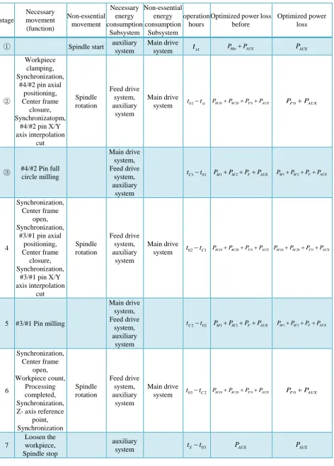
Table 1. CKM200 crankshaft inner milling machine tool pin milling process cycle breakdown table. stage Necessary movement (function) Non-essential movement Necessary energy consumption Subsystem Non-essential energy consumption Subsystem operation hours
Optimized power loss before
Optimized power loss
① Spindle start auxiliary system
Main drive
system tst PMstPAUX PAUX
②
Workpiece clamping, Synchronization,
#4/#2 pin axial positioning, Center frame
closure, Synchronizatopm,
#4/#2 pin X/Y axis interpolation cut Spindle rotation Feed drive system, auxiliary system Main drive
system t01tst PM10PM20PF0PAUX PF0PAUX
③ #4/#2 Pin full circle milling Main drive system, Feed drive system, auxiliary system 01 1 t
tC PM1PM2PFPAUX PM1PM2PFPAUX
4
Synchronization, Center frame
open, Synchronization,
#3/#1 pin axial positioning, Center frame
closure, Synchronization,
#3/#1 pin X/Y axis interpolation cut Spindle rotation Feed drive system, auxiliary system Main drive
system t02tC1 PM10PM20PF0PAUX PM10PM20PF0PAUX
5 #3/#1 Pin milling
Main drive system, Feed drive system, auxiliary system 02 2 t
tC PM1PM2PFPAUX PM1PM2PFPAUX
6 Synchronization, Center frame open, Workpiece count, Processing completed, Synchronization, Z- axis reference
point, Synchronization Spindle rotation Feed drive system, auxiliary system Main drive
system t03tC2 PM10PM20PF0PAUX PF0PAUX
7
Loosen the workpiece, Spindle stop
auxiliary
system tSt03 PAUX PAUX
the main drive system, the no-load energy consumption of the feed drive system and the auxiliary system energy consumption. The machine input power at this time can be indicated as Equation 5.
AUX F AUX
F M
M P P P p p p P
P
P10 10 20 0 01 02 0 . (5)
In Phase ② the miller mainly completes the function of the axial positioning before the full-round milling of the #4/#2 pin; In Phase ④ the machine mainly performs the axial positioning function
before the full-round milling of the #3/#1 pin; At Phase ⑥ the miller mainly performs the Z3 axis
back to the reference point movement after the #3/#1 pin full circle milling finished. Therefore, the non-essential motion of phases②, ④ and ⑥ is the spindle rotation, and the corresponding non-essential energy-consuming subsystem is the main drive system, and the unnecessary loss isPM10PM20.
Process is optimized in Phases ② and ⑥, delaying the spindle start-up time to the end of phase ②, which is after axial positioning of the pin #4/#2and before #3/#1 pin X/Y axis empty cutting interpolation; the spindle stop time is advanced to the beginning of phase ⑥, after the center frame is opened. The no-load loss of the main drive system in phases ② and ⑥ is greatly weakened, and such that the goal of reducing CKM200total energy consumption can be achieved.Considering that phase ④is between two milling stages, it is not advisable to start and stop the spindle frequently in a short
period of time, so phase ④ is not optimized and remains unchanged.
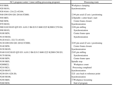
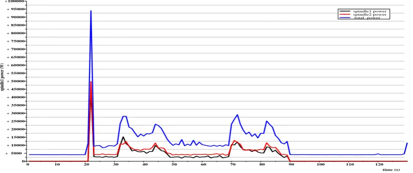
[image:6.595.67.537.413.764.2]The process and procedure of the inner milling processing optimization of the cutter head 1 are shown in Table 2. Figure 6 shows the input power curve after the optimization of the CKM200 pin machining process.
Table 2. Process and program for optimization of internal milling of cutter head 1.
NC1 program (cutter 1 inner milling processing program) Processing route
N10 M68; Workpiece clamping
N20 M101; Synchronization
N30 #164=-216.22+#2104;
N40 G90 G94 G01 Z#164 F2000; ①#4 pin axial (Z axis ) positioning
N50 M03; ②Spindle ( cutter head ) start
N60 M58; Center frame closure
N70 M102; Synchronization
N80 G102 R105 Q29 S51 A101.5 B6 E19.5 I680 J225 K2000 C270 D4; ③#4 pin milling
N90 M103; Synchronization
N100 M59; Center frame open
N110 M104; Synchronization
N120 #163=-322.72+#2103;
N130 G90 G94 G01 Z#163 F2000; ④#3 pin axial (Z axis ) positioning
N140 M58; Center frame closure
N150 M105; Synchronization
N160 G102 R105 Q29 S51 A101.5 B6 E19.5 I680 J225 K2000 C90 D3; ⑤#3 pin milling
N170 M106; Synchronization
N180 M59; Center frame open
N190 M05; Spindle stop
N200M22; Workpiece count
N210 M21; Processing completed
N220 M107; Synchronization
N230 G91 G28 Z0; ⑥Z- axis back to reference point
N240 M108; Synchronization
N250 M69; ⑦Workpiece loosening
0 10 20 30 40 50 60 70 80 90 100 110 120 0
+ 5000 + 10000 + 15000 + 20000 + 25000 + 30000 + 35000 + 40000 + 45000 + 50000 + 55000 + 60000 + 65000 + 70000 + 75000 + 80000 + 85000 + 90000 + 95000 +100000
sp
in
dl
e1
p
ow
er
(W
)
time (s)
[image:7.595.90.512.72.249.2]spindle1 power spindle2 power total power
Figure 6. Input power curve after optimization of CKM200 pin machining process
At this time, the energy consumption of one processing cycle is as shown in Equation 6.
1 0 1 1363990 T
E
Pdt J. (6) The reduction rate of energy consumption in one processing cycle is as shown in Equation 7.1 100% 1538030 1363990 100% 11.32% 1538030
E E E
. (7)
Summary
1. The crankshaft pin milling process is analyzed from the perspective of energy consumption. 2. Under the premise of not changing the process parameters, the crankshaft inner milling process optimization is carried out, the unnecessary movement is removed or optimized. As a result, the corresponding subsystem consumption is reduced, and the goal of reducing the total energy consumption of CKM200 crankshaft inner milling machine is achieved.
3. The power acquisition platform was built to optimize the inner milling process of the four-cylinder engine ZD30 crankshaft blank pin. The input power data of the machine tool and the two spindle motors were collected and compared by the professional drawing & data analysis software OriginPro 8.
4. The experiment data shows that the system energy consumption is significantly reduced after the process optimization, which is useful for exploring the ways of energy saving and consumption reduction of CNC machine tools and realizing green manufacturing.
Acknowledgements
This research was supported by the National Natural Science Foundation of China (No. 51575211).
References
[1] Yong-sheng Gu, Analysis of rough machining process of crankshaft main journal and pin, World Manufacturing Technology and Equipment Market. 4 (2002) 45-48.
[2] Wei Zhou, Analysis of Crankshaft Machining Process, Development and Innovation of Electromechanical Products. 23 (2010) 191-192.