IBM General Information Manual 305 RAMAC Programmer's Guide
CONTENTS
INTRODUCTION 0 0 0 0 • • 0 • • 0 • • • • 0 • • • 0 • • 0 0 • • • • • •
PROGRAM PLANNING . • . . 0 • • 0 • • 0 • • • • • • • • • • • •
Input Consi derati ons . 0 • 0 0 0 • • • • • • 0 • 0 • • • • • • • 0 • • • •
Disk File Considerations •••••. 0 • • 0 • 0 0 0 0 • • 0 • • • • •
Planning . . • • . . . 0 • 0 0 • 0 • • 0 • 0 • • • 0 •
Addressing Methods • . . . . 0 • 0 0 • • 0 • 0 0 • • 0 0 0 • •
Output Considerations • • . • • . • • . • . . . • . . 0 • 0 • • •
Accounting Control and Audit Trail • . . • . . . • . . . • . . 0 •
Multiple Routines . . . . • 0 0 • • • 0 • • • 0 • • 0 • • 0 • • 0 0 • •
MACHINE General
PROGRAM . . . • . . • . • . • . . • . . . 0 • • • • •
Programming Practi ce • . . • . . • • . • . . • • . . • . . . •
Programming Aids . . • • • . • . • .. .. 0 • 0 • • • • 0 • • 0 • •
The Stored Program ..•• 0 0 • 0 • 0 • • • • 0 • • • • • • 0 • • • 0
Format Design and Multiple Transfers. 0 0 • • • • • 0 •
The Magneti c Core Unit •••. 0 0 • • • • • • • • • • • 0 0 0 0 0 0 •
The Accumulators . . . . 0 • • • 0 • 0 • 0 0 • • • 0 0 0 • 0 • 0
The Instruction Register .. 0 • • • • • 0 • • 0 • • • • • • •
Instruction Modification 0 0 0 • • • • • • • • 0 • 0 0 0 • • •
The Process Control Pane I . . . 0 • • • • • 0 • 0 0 0 • • 0 • 0
Programmed Checking ••. 0 • • 0 • • • • 0 0 • • • 0 • • 0 • • • 0
System Speed
0... ... .
OPERATIN G THE 305 • 0 0 0 . 0 • • 0 0 • • • • • • 0 • • 0 • • 0
Manua I I nqui ry o. 0 0 0 • • • 0 • • • • • 0 • • • • • • 0 • • • 0 . . .
Test Data . 0 • • • • • • • 0 • 0 • • • • • • • • • • • • • 0 • • • o • •
Console Operation
MISCELLANEOUS Common Mistakes
Documentati on . . . .. 0 • • • • 0 • • • • • • • • • • • • • • • • •
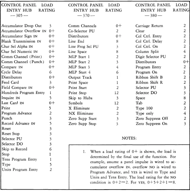
The Control Panel Function Chart (Figure 55) .• 0 • • • • • • •
Special Features 0 • • • 0 • • 0 • • • • • • • • • • • • 0 0 • • 0 0 • •
Additional Disk Storage . . . 0 • • • • • • • • • • Dual Access . . . . .. Processing Drum Tracks . . . 0 •
Program Exit Split . • . . . 0 • 0 0 • • •
Automatic Division . . . 0 0 • • • • • • 0 0 •
Dual Process .. 0 o. 0 • 0 0 • • • 0 • 0 • 0 • • • • • • • • 0
IBM 382 Paper Tape Reader .. 0 • • • 0 • • 0 0 • 0 • 0 • •
IBM 381 Remote Printing Station .. 0 • 0 0 0 • • • • • •
Input Rearrangement and Input Analysis Features
INTRODUCTION
One constantly sought after goal of a machine installation is increased speed and accuracy in the accomplishment of its assigned task.
To obtain these optimum results with the IBM 305 RAMAC, certain programming features must be considered in the utilization of its components. Effective use of all stored program and control panel features, proper use of the disk file and good operating techniques all playa major role in producing an efficient program. This manual is intended to serve as a guide for developing detailed machine
PROGRAM
PLANNING
Information is normally processed in the 305 by a continuous-flow type
operation. Thus, a transaction enters the system via the card reader and, after processing, generally results in an output document being produced. It is
obvious, then, that no one area of the system can process more items than another. Also, the over-all transaction processing speed will be determined by the speed of the slowest area. Therefore, for maximum operating efficiency, all areas of processing should be balanced as closely as possible.
The areas listed in this section are separated as a convenience for study and program analysis. Each of the areas has a real effect on the others; therefore, they must all be considered and planned as one, rather than as a series of isolated steps. There is a natural tendency to disregard output considerations until after the rest of the program has been planned. This is a serious mistake in a continuous-process system and may become a bottleneck for the entire operation. The 305 machine program, from source document to machine output must be considered as a whole. A proper balance in all of these areas will assure maximum efficiency of the over-all system operation.
The process to develop a program is basic to one set of control panels and stored instructions. The same general procedure should be followed for each program consisting of separate control panels and stored instructions. For example, in a complex billing application, it may be desirable to process Receipts and Issues with one program and other types of transactions with a separate program. Although each program should be treated separately, decisions made in one program should be continuously related to the other to arrive at the best compatible arrangement.
INPUT CONSIDERATIONS
Data input to the 305 is by IBM punched cards. The read brushe-s sense the punched holes from the back of the card; therefore, sense markIng on the front of the card will not affect the accuracy of punched-hole reading. However, sense marking on the back of the cards may cause erroneous card reading and must not be used.
"bit" more than once in the combined punchings will be detected as an error. For instance, a card column double-punched 9-5 will signal an error because a "1" bit is used in both the "9" and "5". A card column double-punched 6-1 will not cause an error signal because no bit is common to both digit values. The bit structure for all characters used in the RAMAC is shown in Figure 1.
o 1 2 3 4 5 6 7 8 9 A B C DE FG HI J K L MN OP OR S T U
v
Iw xy Z &. o - $ * /'*
# @ BIo X 1 2 4 8 C I I I
Figure 1
I I I I
I I I I I I
I I I I I I
I I I I
I I I
I I I
I I
I I I I I I
I I I I I I I I I I I I I I I
I I I I I I I I I
I I
I I I I I I
I I I I I I I I I I I
I I I I I I I I I I I
I I I I I I I I I
I I I I I I I I I I I I I I I I I
I I I I I I I I
I I I I I I I I I
From a systems standpoint, two types of cards may be used for input.
1. Single-item (or transaction) cards.
2. Multi-item cards (usually referred to as spread-item cards).
I I I I I
I I I I
I I
The single-item card, as the name implies, contains information pertaining
I I I
I I I I
to only one item or transaction. It may be produced automatically by various methods. When this is done, it may be desirable to punch the same information in several fields of the card. The format on the card should be arranged to facilitate the transfer of data within the 305.
The spread-item card is used when the amount of information required for each item is limited (Figure 2).
Figure 2. Spread-Item Card
The main advantage of the spread-item card is that it reduces card volume. However, single-item cards are easier to incorporate in audit trails and in any processing that may be necessary with unit record machines. Program restart routines usually are more difficult with spread-item cards.
operation is performed to move items 2-9 one field to the left. The slide instruction for Figure 2 would be K86 K79 63 A6. Note that, as item 9 is moved into the item-8 position, the item-9 position is blanked. Thus, as each slide operation is performed, another item position on the track is blanked. After the 9th slide operation, all 9-item positions will be blank and the blank transmission selector will be transferred. Program exit A, of the slide instruction, tests for blank transmission on each slide operation, and at the appropriate time causes a new card to be read.
To minimize card-read time ,some programs have employed a "stacking" technique. This involves reading several cards into the machine on a series of tracks. Each time a card is used off the end, the card data tracks are shifted and a new card is read from track K. This technique, in some cases, can
save card-read time. However, it places an undue burden upon the operator whenever a restart routine is required. For this reason, it is not recommended except in very unusual situations.
All data entered into the RAMAC should be verified for correctness. There are many ways of providing this verification, such as the self-checking number device for part numbers, the proof punch for accumulation of control totals, accounting machine balancing, pre-punching, and complete verification with the various types of verifiers. This is of major importance since many RAMAC applications will involve the updating of multiple records with input data, and if the basic data is incorrect, it is immediately reflected in many records. The process of correcting these errors is both time-consuming and costly, and can nearly always be avoided through the use of proper verification methods.
DISK FILE C ONSIDERA TIONS Planning
The disk file is the heart of the RAMAC. It provides the means to store extensive records and allows each record to be available for use almost im-mediately. In order for this facility to be utilized most efficiently for any given application the programmer must select a suitable file arrangement. Among the factors to be considered are:
1. the number of different types of records, 2. the number of records within each type,
3. the number of characters in the records of each type,
Information pertaining to items 1, 2, and 3 is used to determine the total file storage requirement. It may sometimes develop that there is more information to be stored in the file than there is storage capacity. Further study might disclose that it would not be economical to keep all this data in the file, even if there were capacity. For instance, one RAMAC program seemed to require file storage for 25, 000 customer records alone. It was later determined that only 10 percent of these customers were active more than once per year. Similar situations have been found with many items in inventory control. When this occurs, it is best to store the most active items in the file and handle the
remainder on an exception basis. This can be done by either pre-analyzing the card and preventing it from entering the machine if it refers to an item not in file, or constructing a program which recognizes this situation and signals the condition by punching a card or typing an appropriate message. If there is the possibility of an input card referring to an item not in file, provision rI1ust be made for this condition.
Another factor which must be considered in planning file space, is that of future expansion. If future requirements cannot be determined realistically, a minimum of 10 percent should be left for this purpose.
Although the file is divided into 50,000 one-hundred character sectors, each directly addressable by a five-digit number, there is nothing to prevent the utilization of longer or shorter records. For instance, if the record length were 200 characters, then two 100-character locations would be required for each 200-character record. The capacity of the file would be 25,000 records of this type. If direct addressing were used for item numbers 00000 through 24999, the even numbered file addresses could be used for the first 100 characters and the next higher address for the second 100 characters of the record. An
item number 13493 would be multiplied by two to develop file address 26986, and its next higher location 26987. Item 13494 would occupy address locations
26988, 26989, and so forth.
Another method of locating records greater than 100 characters is to seek the first file location of the record by its addre ss and record advance for the remaining locations. If the record is not stored in consecutive locations, each location can contain, along with its part of the record, the address of the location of the next part of that record.
track position. For instance, item 12345,Q would locate 12345. The sixth digit (3) would be used to modify the processing programs so as to refer to the third division of the record. An example of this method is shown on page 43. Combinations of long and short records can be devised to answer a particular need.
Addressi ng Methods
Considerable time and effort have been spent on developing methods that will yield maximum efficiency in addressing the disk storage of the 305 RAMAC. To achieve this maximum efficiency, data must be stored, and subsequently retrieved, in a manner that minimizes the average time required to locate an item in storage, and also minimizes the amount of unused (but assigned) storage space. The ideal addressing method, therefore, will yield a file that utilizes 100 percent of the disk storage area allotted to it and in which each item can be located with only one seek.
Several different methods of disk file addressing have been developed. Each of these methods has certain advantages and disadvantages which vary in im-portance according to the nature of the data composing the file. The methods may be divided into two general categories, direct addressing and indirect addressing.
Direct Addressing
In using the direct addressing method, certain information in each record is used, either directly or by a simple conversion process, to provide the disk file address. This information is usually the control data of the record (i. e., an identifying part of the record such as employee number, part number, or account number). This control data most frequently will reflect a change or addition that was made in order to facilitate disk file addressing, but could be an original part of the record.
The advantages obtainable by use of direct addressing are:
1. 100 percent utilization of file storage space can be attained.
2. Access time is minimized as each item can be located with only one seek. 3. No machine time is required to convert the control data of the record to
a file address.
4. No cross-index is required for inquiry.
5. File maintenance (additions and deletions) can be easily handled.
From a processing viewpoint, therefore, direct addressing is the most efficient method of disk file addressing and should be used whenever practical. The practicality of using this method can be determined by weighing the benefits derived from the advantages, just enumerated, against the cost of changing the control data to conform with direct addressing.
Indirect Addressing
In some applications, it is not practical to use direct addressing. These
situations usually arise because no part of the records will directly be, or easily convert to, disk file addresses. Also, there will be a few instances in which direct addressing will not be possible because the available addresses, if used, will result in an excessive amount of wasted file space. In either case, it will be necessary to use indirect addressing methods.
In developing an efficient indirect addressing system, the basic issues to be resolved are address conversion and disk file addressing. In address conversion the control data must be operated on by a procedure to provide an address within the desired range. This procedure, which is illustrated in Figure 3, consists basically of the following three steps:
Step 1. An arithmetic process must be devised which will, when applied to all control data, produce a suitably random distribution of numbers in a given range. This is usually 00000-99999 when converting control data to five-digit addresses and 0000-9999 when converting to four-digit addresses.
A
Number Conversion
STEP 1
Range of Control Data
*
B
Randomly Distributed Series of Numbers Between
00000-99999
Compression STEP 2
Displacement
Between Limits of Assigned File Storage Addresses
30000
39999
49999
99999
E_ ---_____________________
T
Step 3. If necessary, a displacement constant is now added to the number series. This displacement constant is equal to the first address of the file area to which the items are assigned. For example, 30, 000 could be added to the number series 00000 to 09999 to develop disk file addresses 30000 to 39999.
The illustration shows that address conversion is like a funnel directing data into the file. The example illustrates the use of 10, 000 file sectors to store data from a list of identification numbers (control data) with possibilities far exceeding this number. However, in the example, it should have been determined that the maximum number of actual sectors required was approxi-mately 8500. In planning a conversion method, it must be determined how many numbers are used in a system having a given number of possibilities.
Experience has shown that the first step in planning an address conversion process is to develop a complete knowledge of the control data. One point to remember here is that the zone portion of alphabetic characters is not used in the 305 arithmetic circuits, except in the sign-control positions. Therefore, the study should be made on the basis of the numerical portion of the control data only. One approach to this study is to develop a distribution of the existing numbers between the two extremes (lowest to highest). This distribution will illustrate the requirements of the address conversion process. Another approach is to develop statistics relating to the control data. A count can be made to determine digit distribution within each number position. Also, the frequency of "pairing" of digits between columns should be considered. For instance, the distribution of individual digit values in each of two columns may be nearly even, but most of the 3's in one column may coincide with the 6's in the other to form a constant of 36. Thus, there will be few 16's, 26's, 46's, 35's, 37's, and so forth. For these counts, IBM unit record equipment can be used.
There is no common formula which will produce uniformly good results in all cases. For each application, a formula must be selected which is best suited to the conditions of the particular situation. Several conversion processes should be tried and evaluated before deciding on the final process to be used. Any standard IBM calculator can be used to compute the converted addresses in the same manner as would be done by the 305. One card is punched with the control data for each item to be stored in the file. These cards are processed through the calculator and the computed file address punched in each card. Some calculators may even compute the converted address for several different formulae on one pass of the cards.
In developing an address con version procedure, the over-all objective is the production of addresses which will aid in achieving maximum efficiency in 305 RAMAC disk file addressing. Five factors should be considered in this context: overflows, item activity, file packing, file maintenance, and machine processing time. The latter four factors may be considered in their relationship to overflows.
Items which are located in home addresses (the original address developed in converting control data) may be retrieved with only one seek; overflows (items which are not located in the original developed address) require more than one seek. It is obvious, therefore, that minimizing the references to overflows will minimize the average seek time required to locate each record. This is
accomplished by minimizing the number of overflows, and by locating those items which are referred to most frequently in, or as near as possible to, home
addresses; i. e., minimizing overflow items, which are among the more active items of the file. Thus, file activity is an important factor to be considered in developing an addressing procedure. If the expected activity of all items in the file is approximately equal, then file activity will have little influence on average seek time per record.
However, if file activity is unequal (e. g., 20 percent of the items account for 70 percent of the total transaction activity), it will have a considerable influence on average seek time. In this latter case, seek time will be minimized if the more active items are located in, or as close as possible to, their ,respective home addresses. The conversion technique should therefore be designed, primarily, for performance on the high-activity items, and those items should be loaded into the file first, thus giving them priority locations. If several seek operations are required to locate an item referred to only once a week, it will have little over-all effect.
Therefore, records should be packed as loosely as possible in the disk storage area.
The effects of subsequent file maintenance should, if possible, be estimated. As mentioned earlier in this section, a complicated formula yielding near-perfect results will usually be extremely sensitive to control number changes. A small number of additions and deletions may have a major effect on its performance.
Finally, the machine processing time required to convert control data to disk file addresses should be considered.
Address conversion procedures can be evaluated, in terms of average seek time per record, by using the methods described in the 305 RAMAC Bulletin, "The Chaining Method of Disk File Addressing for the 305 HAl\LL\ ... C," form J28-2008. If the converted addresses are to be used in a "chaining" process, an evaluation may be made exactly as described in the bulletin. Addresses developed for use in an "Indexing" process can be evaluated by pretending that they are for chaining and following the procedures described in the bulletin. The number of seeks per home address required to locate all records in the chain should be developed as indicated in Figure 2 of the bulletin. For example,
if nine records can be stored on each track, the following chart would be developed.
References 9 Records References 9 Records References 9 Records per Address per Address per Address per Address per Address per Address
1 1 8 8 15 36
2 2 9 9 16 44
3 3 10 11 17 53
4 4 11 14 18 63
5 5 12 18 19 74
6 6 13 23 20 86
7 7 14 29 etc.
---Whenever an indirect addressing method is used, it is necessary to maintain a cross-index reference for manual inquiry purposes. For each item loaded in the file, a card should be punched containing the control data and actual file
address of the item. These cards can be used to print the cross-index reference.
Because any address conversion procedure will develop a varying number of duplicate addresses (synonyms), methods must be provided for locating those records (overflows) that are not in the original address developed (the home address). The remaining portion of this section is devoted to a discussion of these methods. An outline of basic concepts and concerns that pertain to any and all methods is presented first. This is followed by discussion of three specific methods: Next Available Address, Indexing, and Chaining. The discussion of each specific method parallels the outline of basic concepts and concerns.
Basic Concepts and Concerns
1. Address Capacity--How many items can be located in each address? 2. Nature of Items in Each Address--Is each item an actual record, or is it
control data which will be used to locate an actual record?
3. Retrieval of Overflow Items--How will overflow items be retrieved from disk storage? One technique for accomplishing this requires an address search procedure; another requires specific overflow addresses stored at the home location and each successive overflow location. These techniques function as follows:
a. Address Search Procedure--In this technique, the home address is examined to see if it contains the desired item. If it does not, a set pattern of searching other addresses (usually, but not necessarily, the next higher sequential address) is used until the overflow item is found. An example of an address search procedure is included in the discussion of the "next available address" method.
b. Specific Overflow Address--In this technique, as in the preceding one, the home address is examined to see if it contains the desired item. If it does not, an "overflow address, " which was placed in the home address at the time the first overflow occurred, is sent to the address register, and the overflow location is checked to see if it contains the desired item. If it does not, a second overflow address, which was placed in the first overflow location when the second overflow occurred, is sent to the address
register, etc. This process continues until the desired item is found.
5.
6.
overflow items. Both the storage and retrieval of these items must be taken into consideration in developing a loading program. Further infor-mation concerning these factors is included in the discussions of specific methods.
Deleting Items from the File--l
Adding Items to the File-- 'Provision must also be made for deleting items from the file and adding items to the file. Deletions and additions may be accomplished by various techniques, some of which are described in the following discussions of specific methods.
The Next Available Address Method
Although this method is adequate for some applications, it often will prove to be less efficient because too great a number of seeks will be required, on the average, to find each record. It is included in this manual primarily for illustrative
purposes, and only secondarily as a method to be considered for use in an actual application.
1. Address Capacity--Usually, but not necessarily, one item may be located in each address.
2. Nature of Items in Each Address--Each item is an actual record. 3. Retrieval of Overflow Items--Overflow items are retrieved from disk
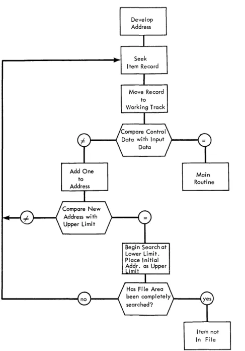
storage by means of an "address search procedure." If the desired item is not found in the home address, the next higher addresses in the disk file are searched sequentially until the desired item is found or the upper limit of the file area is reached. In the latter case, the file area is then
searched starting at the lower limit until the item is not in the file. Figure 4 illustrates this type of address search.
4. Loading the File--The disk file area to be used should be blanked before loading. In this method, the file is loaded in one pass. Each record that cannot be stored in a home address is placed in the next available higher address. This is done by means of a sequential search similar to the one used in retrieving records, except that an address is sought in which the record can be stored. As in any indirect addressing technique, records should be loaded according to expected activity, i. e., the most active items should be loaded first and the least active items last.
Figure 4
Add One to Address
Develop Address
Seek Item Record
Move Record to Working Track
Begin Search at Lower Limit. Place Initial Add.r,. as Upper
ImlT
Main Routine
Item not In File
6. Adding Items to File--Items are added to the file in the same manner as the file is loaded, i. e., the home address is sought and, if empty, the item is placed there. If occupied, a sequential search is used to find the next available address in which the item can be stored.
Indexing
2. Nature of Items in Each Address--Each item is control data that is used to locate an actual record. These control data items are arranged as an "index record" on the zero sector of each track in the same order as the corresponding records are arranged on the disk sectors of the track. This permits use of the built-in field compare and skip-to-record features of the 305 to retrieve all records located on the track.
3. Retrieval of Overflow Items--Overflow items are retrieved from disk storage by means of a '1specific overflow address" procedure. Each zero
sector includes space in which an overflow address can be placed. This address specifies the next zero sector to be examined for the desired item. Thus, when the desired item is not found in the home address, each overflow location which may contain the item is examined sequentially until the item is found, or it is determined that the item is not in the file. Figure 5 illustrates an indexing retrieval process.
Main Routine
Figure 5
Develop Four Digit Address
Seek Zero Sector
Send Input Con-trol Data to Multiplicand Track
Correction Routine
Item Not In File
Read Zero Sec-tor to Working Track to Obtain Overflow Add.
4. Loading the File--Prior to loading, all zero sectors in the file area should be blanked. Loading is accomplished in either one or two passes. During the first pass of two-pass loading, all records are loaded whose associated control data can be placed directly in home addresses. During the second pass, all overflows are loaded. These overflows may be placed in unused locations within the file area or in an area specifically set aside for over-flows. In the latter case, loading can be accomplished as easily in one pass as in two. Locations in which to place overflows can be found by using an "address search" procedure. The loading process must also provide for placing overflow addresses, when required, in the appropriate zero sectors. As in any indirect addressing technique, items should be loaded according to expected activity, i. e., the most active items should be loaded first and the least active items last.
5. Deleting Items from the File--Deletions are made by blanking out the appropriate control data in the index record.
6. Adding Items to the File-- Various techniques may be developed for handling additions. One technique is to locate the home address and:
Chaining
a. If the item can be placed in the home address, place the control data in the zero sector and the record in the corresponding sector of the track.
b. If the item cannot be placed in the home address, proceed to the last overflow sector and place the item in an unused location (i. e., the control data in the zero sector, and the record in the corres-ponding sector of the track). If a new zero sector is involved, place its address in the previous zero sector.
1. Address Capacity--Usually, but not necessarily, one item may be located in each address.
2. Nature of Items in Each Address--Each item is an actual record. 3. Retrieval of Overflow Items--Overflow items are retrieved from disk
Figure 6
Send Overflow Address to Ad-dress Regi ster
Develop Address
Move Record to Working Track
Item Not in File
Main Routine
Space must be reserved in all records of the file for storage of
these overflow addresses. If several records are contained in one sector, each record must contain space for the overflow address. Thus, when the desired item is not found in the home address, each location in the chain is examined sequentially until the item is found, or it is determined that the item is not in the file. Figure 6 illustrates a chaining retrieval process.
4. Loading the File--The disk file area to be used should be blanked
described under the next available address method. The location of each overflow is recorded during loading in the preceding "link of the chain" for subsequent use in the retrieval of these overflow items. As in any indirect addressing technique, items should be loaded according to expected
activity; i. e , the most active items should be loaded first and the least active items last.
5. Deleting Items from the File-- Various techniques may be developed for handling deletions, according to the nature of the application. One technique is to blank out all of the record except the overflow address positions.
6. Adding Items to the File-- Various techniques also may be developed for handling additions. One technique is to locate the home address and:
a. if the home address is empty, place the addition in it;
b. if the home address is occupied, proceed to the end of the chain and by means of an address search procedure, find an unused location in which to place the addition to the chain. If an item has previously been deleted from the chain (this can be checked by a blank transmission instruction), the addition may be placed in the location vacated by the deletion.
OUTPUT CONSIDERATIONS
Output requirements should be developed early in the approach planning stages. A rough estimate of time requirements should be made to determine if they are within the limits of the system requirements.
Second to time requirements, format control and 370 forms-skipping control are the major output considerations. On the 323 Punch, selectors are available on an optional basis only; therefore, on the basic machine only one format is possible without changing the 323 control panel. The format arrangement on the output track must be planned accordingly. The 370 Printer is equipped with eight-line program selectors and four co-selectors. The line-program
selectors have the capacity for six different levels of format. The program should be planned so that this selector capacity is sufficient. One must
remember that each line of an MLP operation requires one level of the selector. Also, only line number 1 of an MLP may be controlled to set up variable
conditions of format. The eight-line program selectors are indiVidually controlled for pickup and dropout, and each has a capacity of eleven positions. Print
positions of line-program selection. A position is also required for each symbol printed that does not always print in the same position on all lines.
Form skipping on the 370 may be controlled by two methods. One, by a significant code on the output track to cause skipping only after a line is printed, and, two from the 305 panel via the communication channels. Skipping may be performed either before or after a printed line when controlled from the 305. However, it is very desirable to control skipping from the output track code whenever
possible. This will facilitate checking out the 370 control panels with the Print Repeat feature, and makes the 370 more independent of the 305 operation. When skipping is controlled via the communication channels, conditions may exist in which the skip will not be executed if the 305 is stopped for some reason. When planning the output, the following pointers should be kept in mind:
1. Print only the information that is actually needed.
2. Design forms, etc., to start printin~ in print position 1. A margin on the left takes print time.
3. Keep lines short.
4. Print constant data on the left, variable on the right. This helps to keep the lines as short as possible.
5. The "delta", Signaling a print error, is printed three positions to the left of print position 1 (that is, two print position spaces between the delta and position 1).
6. Maximum width of forms is 16-1/4 inches from the center of one feed hole to the center of the opposite feed hole. Printing is restricted to the
center 8-inch area of a 16-1/4 inch form. Any 8-inch wide area of a 12-inch form may be printed.
7. Skipping is at the rate of 25 spaces per second.
8. An original, plus seven carbon copies, is the practical maximum.
9. Print all miscellaneous heading data on one line; then other heading lines should be short ones.
10. If more than one MLP operation is used on one control panel, all
11. Have the program determine, just before a Print signal, if a skip is required after the line is printed. If so, place the appropriate skip code on the output track before Print is signaled. This eliminates most requirements for skip control via communication channels.
12. Make the 370 self-supporting; avoid communication-channel control as much as possible.
13. Do not change control panels and forms frequently. Line format, paper forms, and control-panel wiring should be planned to make these changes as infrequent as possible.
ACCOUNTING CONTROL AND AUDIT TRAIL
The theory of in-line data processing, using random access memory, is just as dependent on sound control practices as is any other process. Therefore, every system should include a means of accounting control.
New data processing techniques, such as those offered by RAMAC, may require the development of new control techniques. The responsibility of providing adequate process control rests primarily with the programmer. The first step should be a thorough study of present control procedures. Secondly, the audit and control procedure should be reviewed.
The information gained from these two steps should provide the basis for designing the necessary controls for the RAMAC procedure.
Verification of the various machine processing functions will vary widely,
depending upon the requirements of the particular application. The following are several approaches to the different areas of control:
1. Programmed machine checking. This may include use of a "proof factor", complementary multiplication, or reverse arithmetic. Another vital check is a programmed comparison between the file record and input item
identification numbers.
2. Accounting controls may employ off-line checking using the RAMAC input and output cards. The output cards should be planned to contain all machine-developed data including opening and closing balances.
The degree of control is an important factor and must be carefully established. It has a direct bearing on whether the system is either under-controlled and subject to undetected errors, or over-controlled and wasteful of time and of machine capacity.
Audit trail is the term usually applied to the progression of facts from one
balance point to the next. Audit assumes that data is at hand, or readily available, to enable reconstruction of result data or a process for review.
Both accounting control and audit trail, with particular emphasis on the IBM 305 RAMAC, are dealt with in detail in a separate IDM General Information Manual,
Form 320-0753. This publication is the result of a study by a large public accounting firm, and should be reviewed early in the program planning stage.
M:ULTIPLE ROUTINES
The number and nature of the various machine programs will vary with the application. However, certain generalizations can be made relating to the use of multiple routines.
First, there should be an over-all plan for the use and operation of different routines. For instance, most programs will have separate routines to load the file, unload the file, produce analyses reports, maintain the file, etc. A
schedule should be made of all the routines that will be used and how they relate to each other. The best standard record format design for all programs is a major consideration.
Generally, it is best to store all instructions, constants, etc., for each program in the file. A lead card is then used to transfer the appropriate routine to the processing drum. The functions of the lead card, used to transfer in the new instructions, will be described more fully under Programmed Checking. When the programs are transferred to the drum, prOvision also should be made to clear the accumulators, clear all process tracks, drop out all selectors and accumulator overflow, and set up the emitter track, if one is used. This process is known as initialization.
Features, page 89). Generally, it is best to use the expanded exits as a group and confine their use to subroutines. When this is done, the same controls that transfer the instructions onto the program area also control the exit expansion.
If the program can be designed so that the extra instructions do not have control-panel signals, it will simplify the use of the subroutines.
When multiple routines are used, there usually is a separate set of control panels and input cards for each routine. Therefore, it is necessary to positively
ascertain that the programs, cards, and control panels all match. One way to do this is to assign a discrete alphabetic code to each type of input card. The card column used for the code must be different for each routine. The character selector on each control panel is wired from only those card codes that are proper to that panel. The card column used for the alphabetic code on one routine is used only for unsigned numerical values on any of the remaining routines. Thus, there is a three-way check built into the operation.
If the wrong control panel is installed in the machine, it will stop on a test-for-card code, because only the correct alphabetic codes are wired for selection purposes. If the wrong programs are used, one of the alternate card columns will be transferred to the character selector. Because this is a numerical value and only alphabetic codes are wired, the machine will stop. The same condition will exist if incorrect input cards are used. The control exit, used to test the character selector, may be wired through a combination of
communication channels to test that all control panels match. If all match, a circuit is established to test the character selector; otherwise, the machine stops.
If subsequent tests of the same card code are required along the program, the numerical portion of the alphabetic character may be tested, using the numerical character selector hubs.
Another method used to interlock cards, etc., is to set up a code value for each set of programs, control panels, and cards. A card column must be reserved and used only for program routine number. For example, column 80 in the Issue cards may be coded "1", and this would be compared against a "1" contained in the Issue programs. The control panels can be checked by
reserving one set of character selector hubs for this purpose and wiring only the "1" exit on the Issue panels. The 323 and 370 panels can be tied in by wiring from the "1" hub, through a combination of communication channels and back to a
program re-entry point.
MACHINE PROGRAM
GENERAL
The machine program coordinates the large-capacity random access memory of the RAMAC with the input data either to update the information currently in the file, or to produce a specific type of output. An entire program can be outlined as follows:
1. Consult the input data.
2. Obtain the indicated file data.
3. Combine the input and file information to produce data for updating the file andlor data for output.
Although all programs that follow this outline can be called successful, not all of them can be termed efficient. An efficient prbgram will perform its functions in the least amount of time. Time is one of the principal criteria for evaluating a program.
It follows, then, that a program must be constructed that will process input data (i. e., produce output data) with the greatest possible speed. While there are other considerations in a desirable program, such as the number of program exits used, drum and file space used, etc., it will generally be found advisable to sacrifice these, if possible, to achieve greater output volume.
The machine program consists of two elements: a stored program (i. e., a
list of instructions preloaded in the machine) and the wired process control panel. While the stored program is basically used to transfer data within the 305, a program must refer to the control panel for its logical decisions. Therefore, these two elements must be carefully combined to produce an efficient program. Every decision made prior to the writing of the program, from the statement of the objectives of the installation to the details of format design, will affect the final program. In fact, early procedural proposals should be evaluated by
PROGRAMMING PRACTICE
Before considering actual programming techniques, it should be emphasized that programming is an activity in which the qualities of neatness, simpliCity, and orderliness are extremely important.
A program of even moderate complexity will undergo many revisions, both major and minor, between its first draft and final version. Proper records of the instructions and track layouts at each stage should be kept. In this way, possible improvements to the program will become more apparent, accurate transferral of current results to the next version is assured, and a clear basis for discussion of the program with others is provided.
This, by no means, implies that each stage of the program should be written in complete detail. On the contrary, the actual writing of the program in machine language should be deferred as long as possible. When approaching a problem initially, it is best to begin by drawing a very general block diagram (Figure 7).
Header Routine
Seek Customer
Record
Print Customer Information
Next Card
Return to Start
Figure 7
Analyze Input Card
Code
Line Item Routine
Seek Item Record
Process Item Information
Print, Punch Line Item
This practice of drawing a block diagram is already followed by many. However, at this point many programmers begin writing as shown in Figure 8. This is too much detail for this stage of the program development. It is far better to simply write a list of program steps in very general terms. Such as:
1. Move input card to track W, feed card.
2. Move card code to character
selector. Figure 8
Writing in this way allows the programmer to keep his mind solely on the data processing problem. He need not concern himself with counting track positions, specifying number of characters, numbering program steps, etc. If the format of the input card is changed to expedite keypunching, no corresponding change is required in the program as written. If an instruction is inserted or deleted, it need not affect the rest of the program, because the steps are as yet un-numbered. In short, the program is in a form that can be revised, improved, reorganized and made more efficient.
When the program has reached what is believed to be its final form, it should be completely and properly documented. In current programming practice the most important document to be prepared is the detailed flow chart as shown on pages 74-80. This flow chart should completely illustrate the flow of each program step, including the control panel functions and their branches. It should include every detail of the program with the exception of the program steps in machine language. These would only tend to clutter the drawing. From this chart the entire program can be visualized and each step analyzed to determine its contribution to the program as a whole. After minor improvements have been made and the "loose ends" taken care of, the program step numbers should be tentatively assigned. From these step numbers the next document, the control panel function chart, can be prepared.
The control panel function chart as shown on page 81, is like a map showing the path of impulses through the control panel feature s. A description
could be prevented and the best wiring conditions determined if this chart were made before wiring the panel.
Next, the record layouts must be carefully recorded in their final form. Examples of the se are illustrated on page 84.
At this stage of the development, the program is ready to be written in machine language. The 305 RAMAC Program Instruction Sheet, Form X26-6343, should be used for this purpose. Space is provided on this form to explain each step fully, and for the wiring diagrams associated with each instruction accompanied by a program exit. The 305 RAMAC Selector Assignment Chart, Form X26-7502, should be used for notes on selector assignment. Examples of these forms are shown on pages 85, 86 and 87.
Finally, wiring diagrams can be drawn for the panels that control output format (i. e., the 370 Printer, 323 Punch, and 380 Console).
The process just described is a proven method of writing and documenting a successful RAMAC program. After gaining some experience, however, the programmer may find it convenient to place some of the burden of coding and documentation on the RAMAC itself. The RAMAC assembly program, mentioned under Programming Aids and described briefly in Section 1 of the Appendix, is a programming tool designed to relieve the programmer of much of the clerical labor associated with program preparation.
PROGRAMMING AIDS
Several programming aids have been developed by IBM. These aids are
designed to assist the programmer in writing a RAMAC program in accordance with the process described. Three of these aids, which are available upon request, are:
1. RAMAC Assembly Program--A program which converts restrictive English language instructions to machine language instructions (see Appendix, Section 1). 2. RAMAC Trace Programs--Two programs that may assist in debugging the
stored program and the process control panel, respectively (see Appendix, Se cti on 2).
3. RAMAC General Purpose Board--A prewired process control panel that can be used for any data processing job on the RAMAC. While the use of this board eliminates those phases of program preparation associated with
THE STORED PROGRAM
In discussing the machine program earlier in this manual, it was stated that one of the principal criteria for evaluating a program was the speed with
which it is executed. In this section of the manual, five items will be discussed which, when used wisely, can become powerful tools in increasing program efficiency. It is important to study each of these areas carefully to derive the fullest possible benefit from them.
Format Design and Multiple Transfers
A basic characteristic of in-line data processing is that all information is processed in a continuous-flow type operation; that is, a single input card will affect the card reader, disk file, and output. Therefore, if the format of the input card, disk record, and output is identical, the program will be reduced to its simplest and most efficient form. However, should the arrangement of all the records be different, the program will require additional steps to rearrange and shift the data, thereby causing a longer and less efficient program.
There can be no question as to the advantages of keeping the input format and file record format identical. This is true both for loading the disks from cards or for unloading the disks to cards. Because card capacity is only 80 positions, it would be desirable to develop disk records in which 80 positions contain variable data and the 20 extra positions contain constant data. In this way, the loading and unloading of each disk record can be accomplished with only one card. If all 100 positions are variable the loading and unloading procedure will require two cards for each record and the processing time will double. If
more than 100 characters must be stored, the constant data should be maintained in one sector and variable data in an adjacent sector.
In designing record formats, it must be remembered that many of the records may be consulted by more than one program.
It is often stated that output format will pose no problem, because the output information can be brought to the output track in any format whatsoever, and the required format wired at the panel with no loss in processing time. While this is true, it must be remembered that each such wired rearrangement of output data requires selection. Thus, only six SO-character output rearrangements are possible through selection at the printer.
At the punch, up to 100 positions of two-way selection are available on an optional basis only.
It would seem, therefore, that in the early stages of planning, the different types of output cards or print lines should be as identical in format as is
possible with the input cards and file records. If and when these specifications are found to exceed the capacity of the standard output panel, a decision must be made as to whether additional program steps or additional control panel features will best resolve the difficulty. The area of output formats must be planned with the rest of the program, and definitely should not be considered as a final detail after the program is nearly completed.
The Magneti c Core Unit
The magnetic core unit serves as an intermediate storage for each transfer of data within the RAMAC. On one revolution of the processing drum, the desired information is read from the source track to the magnetic core. On the following revolution the information is read from the cores and recorded in 1he specified positions on the recording track. By considering what actually takes place during each revolution of the drum, the programmer may make more advan-tageous use of the magnetic core unit.
The first drum revolution is called the From cycle. The actual execution time is 10 milliseconds. As the data is read from the source track, the low-order character, as specified by the instructions, is placed in core position 99. The character to the left of this is placed in core position 9S. Each succeeding character is placed, in turn, in the next core position until the specified number of characters to be transferred is sent to the core, or until the 00 position of the source track is transferred. Those positions of the core unit to which no characters have been sent retain the characters which they were storing from a previous instruction.
This action continues until the number of characters to be transferred, as specified by the instruction, is transferred, or until receiving track position 00 receives a character. The information that was placed in the core during the From cycle remains in the core after the execution of the To cycle. Figure 9 shows what takes place when the instruction W04 XII 08, is given .
•
~~'I~IIL'~III
---JJ!
00,
,
10
T
Track W (Source Track)
"---
,
~
~
' - - y - - i
~---./
r
•
,
,
I
, I ,~
~
, ,I, ,
(~,-
if
____
T_ra_c_k_X (Receiving Track) _ _ _ _ _ _ _ _ ...L..1 ... 1 L..IIL..IL..!L....L..I L..I L..! ... 1 L..I . L . . J 100
10Figure 9
The effect shown in Figure 9 is that a 5-character field from track W was transferred to track X. The instruction specified eight characters to be transferred; therefore, three characters left in the core from the previous instruction were also transferred to track X.
In the example that follows, this feature is utilized and a savings of one pro-gram step is obtained. Fields A, B, and C are positioned on track W
(Figure 10). It is desired to reverse their positions and place them adjacent to each other on track S (Figure 10).
I
Track A B C
W
I
I
:
I
II ! I
[ ! I
j !! I I
01 ' I 12T 31 4
a a a a a
Track
C
S B A
I I I I i I I
, [ I
" I
I I
, I I I I I I
I
I i I I, I I I I II
Figure 10
This is accomplished with two instructions (Figure 11).
FROM TO
No. Prog,
Char- Control Step
Trad Position Track Position acters
XXX W
3
9 S 0 9 13
Ixxx IWIO
9IS
2
2
13
Figure 11
The first step moves field C from positions 30-39 of track W to positions 00-09 of track S. The instruction specified 13 characters to be transferred; therefore, field B, positions 27-29, was transferred to the core unit. The second step transfers field A from positions 00-09 of track W to positions 13-22 of track S. Because the second instruction also specified 13 characters to be transferred, field B, which was left in the core by the previous instruction, is transferred to positions 10-12 of track S.
A hyphen in the From portion of an instruction can be used to transfer the data that was placed in the core by the previous instruction to any desired position. Remember that, when using the core as a "source" track, core-position 99 is always sent to the position designated in the To portion of the instruction. It
Two examples, in which the hyphen was used to address the core unit, follow:
Example 1 (Figure 12)
Accumulators 7 and 8 contain quantities A and B, respectively. It is desired to compute and store 2A + B in accumulator 7, and 2B in accumulator 8. Two instructions will produce this result.
FROM TO Skip
Prog. No. To
Control Description
Step Char- Prog.
ITrod Position Track Posiiion acters I
I
~. ':>Tep Ixxx L 8 9 L 8 9 2 0 This instruction doubles the contents
I
~~--~-of both accumulators. Quantit)l: A is
left in core positions 80-89 and
quantit~ B is left in co~sitions - - - - -
-90-99.
--~~--- -~
~--xxx - 9 9 L 7 9 1 0 Quantity B/ which was left in core
positions 90-99 by the previous
instruction, is added into accumulator
7. Accumulator 7 now contains
2A + B. and accumulator 8 contains
2B.
Example 2 (Figure 13)
Each accumulator contains a positive quantity that must be multiplied by 12. Multiplication by simultaneous addition will be faster than executing 10 multiply instructions. Two instructions will again produce the desired result.
FROM TO
No. Prog.
Step Char- Control Descri ption
Trad Position Track Position acters
xxx L 9 9 L 9 9 0 0 This instruction doubles the contents
of each accumulator and leaves the
origInal~uantity in the core unit.
xxx
-
9 9 L 9 8 9 9 This instruction adds the originalquantity of each accumulator to itself
but shifted one character to the left
to effect multiDlication by 10.
2A (result after first instruction) + lOA (quantity developed by second instruction)
=
12A (result stored in accumulators)Figure 13
Skip To Prog. Step
The behavior of the core unit is slightly different when data is transferred to or from the file; that is, if R99 is used in the From portion of an instruction*, 100 characters will always transfer to the core unit, regardless of the number of characters specified by the instruction. The number of characters specified affects only the number of characters that will leave the core for the receiving track. For instance, if the instruction R99 W79 20 was executed, the entire 100-character file sector would be transferred to the core unit. Only the 20 low-order characters would continue to positions 60-79 of track W.
If R99 is used in the To portion of an instruction, 100 characters will transfer from the core unit to the disk sector, again regardless of the number of characters specified in the instruction. The number of characters specified will control how many characters enter the core prior to the transfer of 100 characters to the disk sector.
It is because of this characteristic of the core unit that the 305 Manual of Operation states 100 characters must always be transferred to and from the disk file. However, an advantage can be obtained through this behavior. An example of this is using the core unit to assemble information. This is illustrated in the following example:
The high-order half of track A and the low-order half of track B are to be assembled and transferred to a disk sector. This can be accomplished with two instructions (Figure 14).
FROM TO Skip
Prog. No. To
Step Char- Control Description Prog.
Trod Position Track Position acters Step
~)()(X
t
.~
..
~
9 9 9 0 0 Transfer the contents of track A to the core unit.- - - - -- - -
---xxx B 9 9
_IL_
9 9r-L
0 Transfer the 50 low-order characters- - r - - - --- - - - -~
-.--~ ---~--- --- -- - - -~-- - - -~-- - - f~om track B to the core unit and transfer contents of core to the disk
_. --- - - - ~--. - - -
-sector. The di_sk sector now contains
f--- --- - - - -- - -
-- - - - --- --- - - - - --- --- - -- - _!he_hl.9..h-order half of track A and the
low-order half of track B.
Figure 14
A compare instruction, using the disk address as the From portion of the
instruction, will also transfer 100 characters to the core unit. If the instruction R99 W04 05 Al is executed, positions 95-99 of the disk sector will be compared with positions 00-04 of track Wand the result stored on the compare selector.
The entire disk record will be left in the core.
I
FROM TO
No. I Skip
Prog. To
Step Char- Control Description Prog.
Trod Position Track Position acters Step
025 L 9 9 J 9 9 0 5 Seek record developed in accumulator 9
--- --- --
-026 -_.- R - -- 9 9 W 9 9 0 0 Transfer record to track W
027 L 9 9 W 0 4 0 5 P 1 C~mpare address wi th address
- - _ . _ ---_.
r - - - -- - - develoeed in accumulator 9.
028 X 9 4 R 9 9 9 5 Transfer record to disk file.
Figure 15
In using the core storage unit to retain information between instructions, there is one point that must be kept in mind: All 100 positions of the core unit are used during certain console operations. Inquiry (manual and programmed) and console-initiated transfers of information between drum and typewriter use the core buffer the same as does a RAMAC instruction. In the last example,
if the RAMAC program were halted after execution of the second instruction, it could be restarted at the third instruction only if no manual inquiry or drum track read operation was initiated at the console. Inquiry would of course, require a restart at the first instruction.
The Accumulators
An accumulator feature, use of which is made frequently in an address con-version formula, is its ability to disregard the zone (X and 0) bits of all incoming alphabetic characters except in the sign control position. (The sign control position is the first, or low-order, character read into an
accumulator.) If J6DV7 is reset in an accumulator, the result will be + 16457.
If 222BSK were entered in the accumulator, the result would be 222222-. When a negative number is read out of an accumulator, the machine will add an X bit to the lowest order digit as the data is enroute from the accumulator track to the core unit. Thus, if 1023- were read out of the accumulator, the result would be 102L.
loaded in a reset accumulator. During each pass of the program loop, 99999 is subtracted from the accumulator. This increases the disk address by one and decreases the number of sectors to be loaded by one.
Thus, if accumulator 9 contains and the arithmetic instruction is executed the re suIt will be
I
000145:12400 199999 000144:12401
I
After all the sectors have been loaded, and the accumulator becomes negative, the program stops. To eliminate storing the constant 99999, the programmer begins investigating his program instructions and finds that instruction 198 reads X99 R99 00. He immediately sees that 99R99 can be used as a constant, and he writes his arithmetic instruction as 185 M99 05.
Care must be exercised in \vriting instructions that address more than one accumulator if negative quantities are involved. For example, initial quantities of + 5, -2, and -3 are to be stored in accumulators 0, 1, and 2, respectively. The required constants are stored on track H (Figure 16) and separated by blanks. Character K (X-2) and L (X-3) are used to deSignate -2 and -3.
o I
a
i i i
i51 .
Figure 16
I
I
III I o
Track H
K
,-11
! 2 I
o ,
(
J ~ )L
i1
1\
I 3 I a j
If the one instruction, H27 L27 23 b5 were executed, accumulator 1 would receive a + 2 rather than the desired -2. The reason is the lowest order digit read into accumulator 1 was a blank, which is not accompanied by an X-bit; therefore, accumulator 1 is positive. To rectify this, a hyphen (X-bit) may be placed in position 19. Another solution is to set the constants as shown in Figure 17 and use the instruction H27 M27 23 b5.
~O~I---~I~I~I---~1-2~1---a 0 0
i5i
I ! ! ! ! !
01
o Figure 17
The RAMAC, maintaining algebraic sign control, will enter these digits as +5, -2, -3.
Another example of the care to be taken in addressing several accumulators with one instruction is the following. A programmer decides to effect a multiplication by eleven by using the instruction L99 L98 49. In this case, five accumulators are affected. To produce the proper result, each accumu-lator affected must be positive with the exception of the last (or right hand) one; this may be negative. The reason is that when the digits are read back from the core unit into the accumulators, they are shifted one position to the left. This means that on each negative accumulator the X-bit will be ignored, because it will not be replaced in the sign control position.
FROM Prog.
Step
Track Position Track
XXX L 9 9 L
xxx
-
9 9 LFigure 18
TO
Position
9 9 9 9
No. Char-acters
5 0
5 0
Control
Multiplication by three, how-ever, can be obtained on five accumulators, regardless of the sign of each individual accumulator. This method uses the advantages of the core unit described in the previous section. The instructions are shown in
Figure 18.
Proper results are obtained in this method because an X-bit, in the sign control position is always returned to the same position, maintaining the proper sign. When reading out of an accumulator, it is best to a void the read out and reset code (M). A basic rule in programming is to retain any stored data until it is necessary to use the storage space for more data. This will facilitate checking the cause of an unscheduled machine stop or error. Also, the familiar
programming error (forgetting to reset an accumulator before storing data there) is less likely. The accumulators can generally be reset with the same instruction that brings data in to them.
The I nstructi on Register
seventh, eighth, and tenth positions. The remaining positions, the first (From track), the fourth (To track), and the ninth (program exit) positions will store alphabetic characters. Thus, if the characters BILLSbPAGE were written as an instruction, they would arrive at the instruction register as B93 L20 71 G5 and would be executed as such. (Each cha