2017 3rd International Conference on Electronic Information Technology and Intellectualization (ICEITI 2017) ISBN: 978-1-60595-512-4
Infrared Dim Small Target Detection
Technology Based on RPCA
Junliang Fan*, Yongming Gao, Zhihuan Wu and Lei Li
ABSTRACT
In this paper, a novel small target detection algorithm based on robust master analysis (RPCA) is proposed to solve the problem of small target difficult to detection in single infrared image. Because of the background matrix is a low rank matrix and the target matrix is a sparse matrix, small target detection can be formulated as an optimization problem of recovering low-rank and sparse matrices. RPCA method is used to restore the background matrix and targets matrix, and then choose the inexact augmented Lagrange multipliers to solve RPCA model which is faster. At last, two simulation experiments result indicate that can adapt to a variety of single image and the timeliness is good for small matrix.
INTRODUCTION
Infrared search and track systems (IRST) has a very important significance in the military application. Infrared thermography technology can make up for radar detection needs to take the initiative to launch radio shortcomings, with all-weather detection capabilities, good concealment and anti-electromagnetic interference. However, the infrared imaging capability is susceptible to the detection distance and the target radiation intensity. The smaller the imaging target when the smaller the detection distance, and the weaker the target intensity when the smaller the target radiation. Therefore, it is an important way to improve the combat effectiveness of
________________________
infrared search and tracking system by studying the weak target detection technology of infrared image.
At present, infrared target detection technology is divided into two categories: image sequence detection and single frame detection theory. The image sequence detection theory is to estimate the target by the correlation of the target in the sequence image. At the very early stage, the most typical is three-dimensional matched filtering [1]. The method can detect the target of uniform motion under the premise of knowing the target shape and speed. A 3D bidirectional filtering method is proposed in[1], which is more capable of accumulating the target energy than the traditional three-dimensional matched filter and can detect the weak target better. In addition, some other sequence detection methods first suppress background clutter or enhance small targets in a single image, and then use multi-frame accumulation, autocorrelation or other techniques to suppress random noise or delete false alarms. The performance of these methods largely depends on the processing results of each frame. A novel target detection method combining support vector machines (SVM) and wavelet domain is proposed in [2]. This method uses SVM to extract the characteristics of each frame in the wavelet domain, and then fuses continuous frames to enhance the small target. The premise of the sequential method is the consistency of the target and background between consecutive frames, as well as the prior knowledge of the target shape and velocity. These prerequisites and prior knowledge are difficult to implement in applications, so small target detection based on single frame is very concerned[1-3].
INFRARED DIM SMALL TARGET DETECTION BASED ON RPCA
A. Theory
Due to the characteristics of long-distance infrared imaging, the target under long-range infrared imaging is usually not obvious, the edge is blurred, the target pixel is little, usually expressed as small bright spot. SPIE defined in an image with a size of, the target size does not exceed and approximately 0.12% of the image pixels are called dim small targets. "Dim" refers to the pixel contrast is low, the target is not obvious, "small" means less pixels. According to the imaging principle of infrared system, a complete infrared small target image is usually composed of small target, background and noise, which can be expressed as:
,
,
,
,D T B N
f x y f x y f x y f x y (1)
Where fDx y, represents the original infrared image, fT x y, represents small
[image:3.612.128.485.374.517.2]target, fBx y, represents the background, fNx y, represents noise,
x y, is the pixel position.Figure 1. Low rank characteristic of infrared image.
The number of small targets is limited in the infrared image which contains some small target, so the proportion of the pixels of the small target relative to the large format background is very small. The proportion of small targets defined by SPIE is 0.12% relative to the image; that is very small number. So the target matrix can be seen as a sparse matrix, that is:
0
,
T
Where 0 denote the lo norm which counts the number of nonzero element. The
parameter k is determined by the size and number of small targets, and k m n (m n represents the size of the matrix fD x y, ).
Because of the atmospheric refraction, dispersion, optical decoupling, lens distortion, diffraction, mirror deformation, detector tilt, infrared image is slightly blurred. There is a certain correlation between the internal structure of the background image of the far-distance imaging, and the non-local autocorrelation characteristic is widely found in the infrared image. The first line of Figure 1 shows four typical infrared images; the second line shows the singular value graph of the infrared image. We can see the four infrared images are different, but its singular values are the same of the characteristics, that singular values are quickly converged to zero. So we can think that the infrared background image matrix is a low rank matrix, which can be expressed as:
B ,
rank f x y r (3)
Where the parameter r is a constant which constrains the complexity of the image.
In order to detect small targets in a single frame infrared image, we assume that no noise is included in the infrared image. This infrared image model is simplified to
D B T, where D is the infrared image, B is the background, and T is the small target. As in the previous discussion on the infrared small target image, the background matrix B can be regarded as an low rank matrix, and the target matrix T can be regarded as a sparse matrix, Therefore, small target detection can be transformed into restoring low rank background matrix and sparse foreground target matrix from an image matrix. There are two methods to solve this typical matrix restoration problem, namely, Principal Component Analysis (PCA) and Robust Principal Component Analysis (RPCA). PCA mainly solves the recovery of background matrix under independent and identically distributed of Gaussian noise. RPCA method is more extensive, only the matrix T has enough sparseness, so this paper presents an infrared weak target detection technology based on RPCA.
The RPCA method is proposed by Candes on the basis of the Principal Component Analysis (PCA). Because the effect of the PCA method is limited to the problem that the perturbation matrices are independent and identically distributed of Gaussian noise, and the low rank matrix and sparse matrix are proposed.
For a given high-dimensional matrix D can be expressed as:
D B T (4)
conditions in [2]. The RPCA method is specifically expressed to solve the following convex optimization problem:
1 ,
arg min
B T
B T ,s.t.D B T (5)
In this formula, denotes the nuclear norm of a matrix, that the nuclear norm
of a matrix is the sum of the singular values of the matrix. 1denotes the 1 norm of a
matrix, that means this is the sum of the absolute values of all the elements of the matrix. Therefore, the RPCA method transforms the problem of separate background images and small targets into solving the above-mentioned convex optimization problem by mathematical method. After the matrix is restored, the position and pixels of the small target in the foreground target matrix are highlighted. Only simple segmentation techniques can be used to extract the target.
This method has the following advantages: (1) the parameters k, r does not need to be estimated according to different images in the (3) (4) formula, the two parameters is not important and does not affect the decomposition results in the calculation. (2) The detection method based on RPCA transforms the target separation process into the mathematical operation of the matrix, which is simple in principle and easy to understand. (3) The robustness of small target detection method based on RPCA is not limited by the size and brightness of small targets, and it can adapt to the detection problem of small targets in cluttered background.
B. Solving RPCA Model
The core of RPCA method is solving a convex optimization problem, the solving methods are Iterative Thresholding algorithm (IT), Accelerated Proximal Gradient (APG), The exact augmented Lagrange multipliers (EALM), The inexact augmented Lagrange multipliers (IALM), the Principal Component Pursuit algorithm (PCP). The larger the matrix dimension, the more time the algorithm needs. At present, the slowest speed is the IT method, and the fastest algorithm is the IALM method, so this paper mainly uses the IALM algorithm.
Lagrange multiplier method is one of the important methods to solve constrained convex optimization problems, which integrated the original function and the constraints into an equation. Here we define constrained convex optimization problems as follows:
min f X ,s.t.h X 0 (6)
The Lagrange function can be defined as:
2
, , ,
2 F
Here, is a definite parameter. And then the augmented Lagrange multiplier theory can be used to solve the convex optimization problem, the specific algorithm flow is in algorithm 1.
The Lagrange multiplier method is applied to solve the RPCA problem, and we can define the formula (6) as follows:
,
X B T ,
1
f X B T ,h X D B T(8)
The Lagrange function of formula (6) can be written as:
2
1
, , , ,
2 F
L B T Y BT Y D B T D B T (9)
The specific algorithm flow of IALM algorithm is shown in algorithm 2.
In the IALM algorithm, the initial setting parameters ,0, ,Y0 are
needed. Article initialization parameters 1 maxm n, , 0 0.3 max
svd D
,3.6
, Y0 D
maxnorm_ max,norm_ inf
, here, norm_ maxmax
svd D
,
_ inf max
norm abs D .
Algorithm 1. General Method of Augmented Lagrange Multiplier. 1,1
2,while not converged do
3,Solve k1 arg min , k, k X
X L X Y
4,Yk1Ykkh X k1
5,k1k
Algorithm 2. RPCA via the IALM Method. input:Observation matrix m n
DR ,
1,Y0D J D ;T00; 0 0;1;k0. 2,while not converged do.
3,//line 4-5 solve k1 arg min , k, k, k B
B L B T Y ;
4, 1
, , k k k
U S V svd D T Y ;
5, 1 1[ ]
T k
B US S V .
6,//line 7 solves k1 arg min k1, , k, k T
T L B T Y
7, 1
1
1 [ 1 ]
k
k k k k
T S D B Y
8,Yk1YkkDBk1Tk1.
9,k1k,k k 1.
10,end while Output:B Tk, k.
EXPERIMENT AND SIMULATION
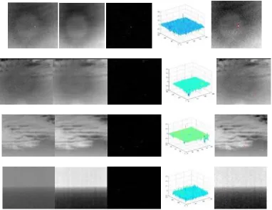
In order to test the effect of this algorithm, this paper chooses Lenovo Think Station D30 workstation, CPU is Intel Xeon E5-2620 and Memory is 32G. In the environment of MATLAB2014a, four typical infrared small target images are simulated, including the sky (a), cloud background (b), the target is partially obscured by clouds (c), sea days handover (d) , include small target. The size of the four images in this experiment is different, the size of figure a is200 150 , the size of figure b is 281 240 , the size of figure c is 250 200 , the size of figure d is
280 228 .
of undulating clouds, and distinguish the open cloud edge and the small target. The experimental results show that the target in the foreground target image is more obvious, and the target can be detected accurately. The fourth line is the results of image d, the small target in the background of sea days handover, and the background difference between the upper and lower parts of the image is relatively large. From the results of the fourth target foreground images, the small target is the brightest pixel in the whole three-dimensional image, and it can locate the small target by finding the maximum pixel value. From three dimensions of the four foreground target, the small target is more prominent in the three-dimensional figure and the background matrix is more flat when the background is relatively simple. The small target is more blurred in the three-dimensional figure and the background matrix is more cluttered when the background is more complex.
Figure 2. Detection results in four different backgrounds.
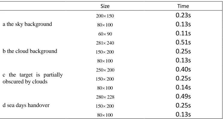
In the simulation experiment, it is found that the running time of different image is different, the algorithm runs time respectively are 0.23s, 0.51s, 0.40s, 0.49s. Therefore, experiment two is designed, and the original image is cut to get small images of different sizes, and then the simulation experiment is carried out for
into 281 240 ,150 200 ,80 100 , image c cuts into250 200 ,150 200 ,80 100 , image
d cuts into 280 228 ,150 200 ,80 100 . After the simulation experiment, we can find
that the algorithm is still able to detect the target under the same background under different sizes, but the time is not the same. The experiment time is shown in Table 1. From the experimental results, we can find that the running time of the algorithm is proportional to the size of the image. Because the algorithm is used to calculate the image as a matrix, the calculation is the operation between the matrix and the matrix. When the matrix dimension is larger, the computational complexity will be larger and the algorithm will run more time.
[image:9.612.112.484.386.586.2]Experiments can be found: (1) This algorithm can detect small objects with small size and no appearance features, and does not require a priori knowledge of the target, and has universal applicability. (2) This algorithm can adapt to the small target detection in most backgrounds, but the complexity of the image background will affect the detection effect of the target foreground image. (3) This algorithm can suppress the influence of partial occlusion target on the detection results of cloud background, and is suitable for the detection of cloud background and target handover. (4) This algorithm is sensitive to image size, the size of the image directly affects the speed of the algorithm, the larger the size of the image, the more time to calculate.
TABLE 1. EXPERIMENT TIME.
Size Time
a the sky background
200 150 0.23s
80 100 0.13s
60 90 0.11s
b the cloud background
281 240 0.51s
150 200 0.25s
80 100 0.13s
c the target is partially obscured by clouds
250 200 0.40s
150 200 0.25s
80 100 0.14s
d sea days handover
280 228 0.49s
150 200 0.25s
80 100 0.13s
CONCLUSIONS
types of infrared images with simple sky background, cloud background, small target and cloud edge coincidence and sea days handover. Experiment 2 simulations of different sizes of images under the same type show that the velocity of the algorithm is inversely proportional to the size of the image. The experimental results show that the detection effect of single frame infrared small target detection technology based on RPCA is better, but the algorithm speed is affected by the image size. In real life, the size of the image may be much larger than the experimental image, the detection time of the algorithm will reach a few seconds or even tens of seconds, so how to improve the timeliness of the algorithm needs further study.
REFERENCES
1. S. Reed, R. M. Gagliardi, and L. B. Stotts, “Optical moving target detection with 3D matched filtering,” IEEE Trans. Aerosp. Electron. Syst., vol. 24, no. 4, pp. 327-336, Jan. 1988.
2. M. Li, T. Zhang, W. Yang, and X. Sun, “Moving weak point target detection and estimation with three-dimensional double directional filter in IR cluttered background,” Opt. Eng., vol. 44, pp. 107007-1–107007-4, Oct. 2005.
3. Z. Wang, J. Tian, J. Liu, and S. Zheng, “Small infrared target fusion detection based on support vector machines in the wavelet domain,” Opt. Eng., vol. 45, no. 7, pp. 076401-1–076401-3, 2006.
4. S. Kim and J. Lee, “Scale invariant small target detection by optimizing signal-to-clutter ratio in heterogeneous background for infrared search and track,” Pattern Recognit., vol. 45, pp. 393-406, Jan. 2012.
5. X. Bai and F. Zhou, “Analysis of different modified top-hat transformations based on structuring element construction,” Signal Process.,vol. 90, pp. 2999-3003, Nov. 2010.
6. Y. F. Gu, C. Wang, B. X. Liu, and Y. Zhang, “A kernel-based nonparametric regression method for clutter removal in infrared small-target detection applications,” IEEE Geosci. Remote Sens. Lett., vol. 7, no. 3,pp. 469-473, Jul. 2010.
7. Xiabin Dong, Xinsheng Huang, Yongbin Zheng, Lurong Shen, Shengjian Bai, Infrared dim and small target detecting and tracking method inspired by Human Visual System, Infrared Physics and Technology,62 (2014) 100-109.
8. H. Deng, J. G. Liu, and Z. Chen, “Infrared small target detection based on modified local entropy and EMD,” Chin. Opt. Lett., vol. 8, pp. 24-28,J an. 2010.
9. Chenqiang Gao, DeyuMeng, Yi Yang, Yongtao Wang, Xiaofang Zhou, “Infrared patch image model for small target detection in a single image”, IEEE Transactions On Image Processing, Vol. 22, NO. 12, December 2013.
10. Wright, J., Ganesh, A., Rao, S., Ma, Y.: Robust principal component analysis: Exact recovery of corrupted low-rank matrices via convex optimization. submitted to Journal of the ACM