HP 9000 Series 800 Computer Systems
CIO LAN Interface Controller (LANIC)
Installation and Reference Manual
2
Notice
The information contained in this document is subject to change without notice.
HEWLETT-PACKARD COMPANY MAKES NO WARRANIT OF ANY KIND WITH REGARD TO THIS MATERIAL, INCLUDING, BUT NOT LIMITED TO, THE IMPLIED WARRANTIES OF MERCHANT-ABILI'IY AND FITNESS FOR A PARTICULAR PURPOSE. Hewlett-Packard shall not be liable for errors contained herein or for incidental or consequential damages in connection with the furnishing, performance, or use of this material.
Hewlett -Packard assumes no responsibility for the use or reliability of its software on equipment that is not furnished by Hewlett-Packard.
This document contains proprietary information, which is protected by copyright. All rights are reserved. No part of this document may be photocopied, reproduc.ed, or translated into another language without the prior written consent of Hewlett-Packard.
Printing History
New editions are complete revisions of the manual. Update packages, which are issued between editions, contain additional and replacement pages to be merged into the manual by the I:;ustomer. The dates on the title page change only when a new edition or a new update is published. No information is incorporated into a reprinting unless it appears as a prior update; the edition does not change when an update is incorporated.
A software code may be printed before the date; this indicates the version level of the software product at the time the manual or update was issued. Many product updates and ftxes do not require manual changes and, con-versely, manual corrections may be done wIthout accompanying product changes. Therefore, do not expect a one-to-one correspondence between product updates and manual updates.
Safety Symbols
ruu,,",,·)
I
I
Safety Considerations
This product and related documentation must be reviewed for familiar-ization with safety markings before operation.
Instruction manual symbol: the product will be marked with this symbol when it is necessary for the user to refer to the instruction manual in order to protect the product against damage.
Indicates hazardous voltages.
Indicates earth (ground) terminal. This symbol is sometimes used in the manual to indicate circuit common connected to a grounded chassis.
The warning sign denotes a hazard. It calls attention to a procedure,
Servicing
General
"'EU,Ii,t.)
6
Any servicing, adjustment, maintenance, or repair of assemblies or
sub-assemblies of the computer system must be performed only by qualified
personnel.
SAFElY EARTH GROUND - The computer in which this product is installed is a safety class I product and is provided with a protective
earthing terminal. An uninterruptible safety ground must be provided
from the main source to the product input wiring terminals, power cord, or supplied power cord set. Whenever it is likely that the protection has been impaired, or before the power cord is removed from the wall
recep-tacle, the interface cable connector must be removed from the computer
system and insulated from exposed conductive surfaces.
I
Caution
I
STATIC SENSITIVE DEVICESWhen any two materials make contact their surfaces are crushed on the atomic level amd electrons pass back and forth between the objects. On separation, one surface comes away with excess electrons (negatively charged) while the other is electron deficient (positively charged). The level of charge that is developed depends on the type of material. In-sulators can easily build up charges in excess of 20,000 volts. A person working at a bench or walking across a floor can build up a charge of many thousands of volts. The amount of static voltage developed depends on the rate of generation of the charge and the capacitance of the body
holding the charge. If the discharge happens to go through a
semiconduc-tor device and the transient current pulse is not effectively diverted by protection circuitry, the resulting current flow throught the device can raise the temperature of the internal junctions to their melting points. MOS structures are also susceptible to dieIectric damage due to high fields.
The resulting damage can range from complete destruction to latent degradation. Small geometry semiconductor devices are especially suscep-tible to damage by static discharge.
For U.S.A. Only
FCC
Notice
The Federal Communications Commission (in 47 CFR 15.838) has specified that the following notice be brought to the attention of the users of this product.
FEDERAL COMMUNICATIONS COMMISSION RADIO FREQUENCY INTERFACE STATEMENT
Warning: This equipment generates and uses radio frequency energy and if not installed and used properly, that is, in strict accordance with the manufacturer's instructions, may cause interference to radio and television
reception. It has been type tested and found to comply with the limits for
a Class A computing device in accordance: with the specifications in Sub-part J of Part 15 of FCC Rules, which are designed to provide reasonable protection against such interference in a commerical environment. Opera-tion of this equipment in a residential area may cause interference in which case the user at his own expense will be required to take whatever measures may be required to correct the interference.
If this equipment does cause interference to radio or television reception,
which can be determined by turning the equipment off and on, the user is
encouraged to try to correct the interference by one or more of the follow-ing measures: re-orient the receivfollow-ing antenna; relocate the computer with respect to the receiver; move the computer away from the receiver; plug
the computer into a different branch circuit. If necessary, the user should
consult the dealer or authorized field service representative for additional suggestions. The user may find the following booklet prepared by the Federal Communications Commission helpful: "How to Identify and Resolve Radio-TV Interference Problems". This booklet is available from
the U.S. Government Printing Office, Washington, DC 20402~ Stock No.
Purpose
Organization
Preface
This manual provides installation procedures for the Channel I/O (CIO) Local Area Network Interface Controller (Lo\NIC) card. Using this manual, you will be able to install a LANIe card into applicable HP 9000 Series 800 computers for connection to a local area network (LAN).
To completely install and operate a host computer as a network node, this manual must be used in conjunction with other manuals. For example, this manual presumes that node location decisions have been made, and network cabling and accessories have been installed. Cable and accessory installation details are discussed in other manuals. Likewise, information on computer operation and network communication software is available elsewhere. The "Technicial Manual Refer,ence" section in Chapter 8 provides a list of related manuals.
Chapter 1
Chapter 2
Chapter 3
Chapter 4
Chapter 5
Chapter 6
Chapter 7
ChapterS
provides a general overview of the CIO LANIC product.
provides site preparation information.
provides hardware installation and configuration procedures for proper card operation.
provides a functional description of the product.
\
describes removal and replacement procedures for serviceable components.
provides basic maintenance and troubleshooting information.
provides a list of replaceable parts used in the LANIC card assembly.
Comment
12
Appendix A
Appendix B
AppendixC
AppendixD
provides reference and installation information for the HP 28641A ThinMAU.
provides reference and installation information for the HP 30241A ThickMAU.
provides reference and installation information for Ethernet.
provides reference and installation information for the HP 28664A Twisted-pair MAU.
Table of Contents
1
General Information
Product Overview . . . .. 1 - 1 Connection to the Host . . . 1 - 1 Connection to a LAN . . . . . . .. 1 - 1 Software . . . 1 - 2 Link-Level (Station) Address . . . . . .. 1- 2 Identification . . . 1 - 3 The Product . . . 1 - 3 Interface Card . . . . . . .. 1 - 3 Manuals . . . .. 1 - 3 Specifications . . . " . . . .. 1 - 4 Features . . . 1- 4 Physical Characteristics . . . .. 1 - 4 Environmental . . . .. 1 - 4 Test Equipment and Special Tools . . . 1 - 5 Support Strategy . . . 1 - 5 Equipment Supplied . . . 1 - 6
- 2
Site Preparation
3
Installation / Configuration
14
5
Removal and Replacement
LANIC Card and Connector Cable . . . .. 5 - 1 Removing the Card Connector (Stub) Cable . . . .. 5 - 1 Removing the LANIC Card . . . 5 - 2 Replacing the LANIC Card . . . 5 - 2 Replacing the LANIC Card Connector Cable . . . 5 - 2 Replacing Components on the LANIC Card . . . 5 - 3 The Fuse . . . 5 - 3
NO~orEPROM . . . 5-3
6
Troubleshooting
Safety Considerations . . . 6 - 1 Troubleshooting Strategy . . . 6 - 1 Maintenance . . . 6 - 2 Preventive Maintenance . . . 6 - 2 Maintenance Aids . . . .. 6 - 2 Local Area Network Device Adapter Diagnostic . . . .. 6 - 3 LANDAD Capabilities . . . 6 - 3 Minimum Configuration . . . 6 - 3 Hardware . . . 6 - 3 Software . . . .. 6 - 3 LANDAD Operational Modes . . . .. 6 - 4 Description ofLANDAD Sections . . . 6 - 5 Section 1 - More Help . . . 6 - 5 Section 2 - Reset . . . 6 - 6 Section 3 - Identify . . . 6 - 6 Section 4 - Local Loopback . . . 6 - 6 Section 5 - Self-test . . . . . . .. 6 - 6 Section 6 - Status . . . 6 - 6 Section 7 - Link Statistics . . . .. 6 - 7 Section 8 - External Loopback . . . .. 6 - 8 Section 9 - Remote Node Test. . . .. 6 - 9 Section 10 - Remote XID Test . . . .. 6 - 9 Section 11 - AUI Cable Fault Isolation . . . 6 - 10 Section 12 - Offline MAU Test . . . 6 -11 Running LANDAD . . . .. 6 - 12 Example of a Diagnostic Session . . . 6 - 14
7
Replaceable Parts
8
Reference
Technical Manual Reference 8-1
Glossary of Terms . . . 8 - 5
9
Schematics and Diagrams
A
UP 28641A ThinMAU
IEEE 802.3 Type 10BASE2 . . . . . . A - 2 Specifications . . . . . . A - 3 Features . . . A - 3 Functional Specifications . . . A - 3 Environmental Characteristics . . . A - 3 Physical Characteristics . . . A - 3 Electrical Characteristics . . . A - 3 Connecting the AUI Cable . . . A - 4 D Connectors . . . A - 4 Diagnostic Set-up . . . A - 5
B
UP 30241A ThickMAU
IEEE 802.3 Type 10BASE5 . . . B-2 Specifications . . . . . . .. B-3 Features . . . B-3 Functional Specifications . . . .. . . B-3 Environmental Characteristics . . . B-3 Physical Characteristics . . . B-3 Electrical Characteristics . . . B - 4 Connecting the AUI Cable . . . B - 4 D Connectors . . . B - 4 Diagnostic Set-up . . . .. B - 5
C
Ethernet
Ethernet and IEEE 802.3
D
Twisted-pair MAU
General Overview . . . D - 2 Specifications . . . D - 3 Features . . . D - 3 Functional Specifications . . . D - 3 Environmental Characteristics . . . D - 3 Physical Characteristics . . . D - 3 Electrical Characteristics . . . D - 3 Connecting the AUI Cable . . . D - 4 D Connectors . . . D - 4 Diagnostic Set-up . . . D - 5
1
Product Overview
Connection to the Host
Connection to a LAN
General Information
This manual presents installation and reference material for the Local Area Network Interface Controller (LANIC) printed circuit assembly (PCA, also referred to as card) and card connector cable (stub cable) used with the Channel I/O (CIO) LAN Link. This chapter provides a general overview of the product.
The LANIC connects an HP 9000 Series 800 host computer to a Local Area Network (LAN). With appropriate network software, the host
becomes a node on the LAN, and can access and communicate with other
nodes.
The LANIC operates with 10 megabit-per-second baseband networks
using a Carrier Sense Multiple Access with Collision Detect (CSMNCD)
protocol for network access. Baseband impllies that a single channel uses the entire bandwidth available and is shared by all the nodes on the network. CSMNCD implies that the nodes gain access to the common channel through a contention process whenever the channel is free of traffic, without the use of a master node.
The Local Area Network Interface Controller (LANIC) card is an input/output (I/O) card that plugs into the Channel I/O Bus (CIB) of an
HP 9000 Series 800 host computer. An SO-pin connector (J1), located on
the LANI C card, mates with connector pins on the CIB when the card is inserted into the CIB card cage.
Software
Link-Level
(Station) Address
1-2 General Information
The LANIC is supported under HP-UX (Revision B.02.00 or later) on HP 9000 Series 800 Computer Systems.
The LANIC supports the Hewlett-Packard LAN/9000 Series 800 link.
Installation instructions for link software are discussed in the Installing
LAN/9000 Series BOO manual, part number 98194-90009. Note that LAN/9000 Series 800 software supports both Ethernet and IEEE 802.3.
All the ARPA Berkeley, NFS, and NS products will run on top of the LAN/9000 Series 800 link software.
The link-level station address is a 12-digit hexadecimal number that uniquely identifies each node. This address is associated with the Data Link Layer (level 2) of the International Standards Organization (ISO) Open Systems Interconnection (OSI) model, and should not be confused with "internet" or other addresses associated with higher layers. During normal node operation, the destination address of a received packet is
matched with this address to determine if the packet is accepted for
processing. In addition, the node's station address is appended to trans-mitted packets for source node identification.
The station address is assigned at the factory and stored in the card's
NOVRAM (non-volatile, static RAM). It is globally administered, that is,
it is a unique node address regardless of manufacturer. Refer to Chapter 3 to determine the address of your LANI C card.
The node's station address is changed if the NOVRAM is physically
replaced. To replace the NOVRAM, see Chapter 5. If the address
Identification
The Product
Interface Card
I
Notel
Manuals
Up to five digits and a letter (HP 12345B as an example) are used to identify Hewlett-Packard products. The digits identify the product; the letter identifies the revision level of the product.
The card supplied with the LANIC product is identified by a part number printed on a white sticker affixed to the carel In addition to the part number, the card is further identified by a letter and a 4-digit date code
(e.g., A-1234). This designation is placed below the part number. The
letter identifies the version of the etched circuit on the card. The date code (the four digits following the letter) identifies the electrical
characteristics of the card with components mounted. Thus, the complete part number on a card could be as follows:
5062-3313
A-1234
Note that the date code on your card will bt! the current revision of the
assembly, not the number given in the above example.
If the card is already installed in the computer backplane, the legend
"802.3" is imprinted on the left-hand extractor lever.
Specifications
Features
Physical
Characteristics
Environmental
1-4 GeneraLlnformauon
LANIC specifications are shown below.
Capacity
Transmis-sion mode
Data Trans-fer Rate
Size Weight 10 Channel Interconnect Device Interconnect Operating Non-operating Electro-magnetic Voltage Current (AMPS) Power (WATTS)
Single (transmit or receive) communication channel with up to 64 Kbytes of RAM for buffering both receive and transmit packets.
CSMNCD, bit serial, Manchester encoded, variable packet size from 64 to 1518 bytes.
Transmitted in bursts at 10 Mbits/second. Through-put capacity is processor and process dependent.
19.3 cm by 17.1 cm by 1.59 cm (7.6 in. by 6.75 in. by 0.75 in.)
280 grams (10 ounces)
One 8O-pin female connector (Jl) connects to the host computer's Channel I/O Bus (CIB)
One 26-pin male connector (12) connects to a card connector cable (stub cable)
00 to
+
550Celsius
-4()0 to
+
750 CelsiusConforms to VDE Level B and FCC Level A for radiated and conducted interference.
+5V
+
12V*3.00 0.50
15 6
Test Equipment
and Special Tools
Support Strategy
The following items are available from Hewlett-Packard for testing the LAN node:
• HP 92257B MAU Test Fixture
• HP 92257Q ThinMAU Test Fixture
• HP 5061-4977 Twisted-pair MAU Loopback Connector
The above test fIXtures are available through the nearest Hewlett-Packard Sales and Support Office. The Loopback Connector comes as part of the Twisted-pair Option. All the above items are also available from the Hewlett-Packard Direct Marketing Division.
Equipment
Supplied
1-6 General Information
Standard equipment supplied with this product is operationally
compatible with the IEEE 802.3 standard. Included is one of each of the following:
Part Number 5062-3313 5959-2259
28641-60004 28641-90001 1250-0781 1252-1650
Description
LANIC Card Assembly CIO LAN Interface Controller
Installation and Reference Manual (this manual) ThinMAU
ThinMAU Installation Manual BNC "T" Connector
BNC "T" Connector Cover
The product also includes the appropriate Link software and associated manuals for your computer system.
The following options are also available:
Option #740 - Deletes the ThinMAU and adds aThickMAU.
Option #840 - Deletes the ThinMAU and adds a Twisted-pair MAU.
Option #841- Deletes the ThinMAU.
Option #lAW - Hardware only Option.
Option #AAl- Replaces l!4-inch tape with 1600 BPI 1!2-inch tape.
2
Site
Pre~aration
Because the Channel I/O (CIO) LAN Link is part of an HP 9000 Series 800 Computer System, this manual assumes that all computer-level site preparation procedures have been followed and that the appr9priate cabling has been installed for your type of LAN network. Supported cabling includes one of the following:
1. "Thin" RG58 NO or C/V coaxial cable (approximately 4.9 mm, 0.019
inch diameter) with BNC connectors at each node location, and:
a. IEEE 802.3 Type 10BASE2 hardware: HP 28641A ThinMA U
with BNC "T" adapter connected to the coaxial cable, or
b. Ethernet-based hardware for accf:ssing thin-cable LANs.
2. "Thick" coaxial cable (approximately 10 mm, 0.4 inch diameter), and:
a. IEEE 802.3 Type 10BASE5 hardware: HP 30241A MAU with tap connected to the coaxial cable and AUI cabling from the MAU to the host computer, or
b. Ethernet-based tap and transceiver assembly, and branch cabling to the host computer.
3. Unshielded twisted-pair cabling which meets HP's SiteWire
require-ments. If you are in doubt about whether your wiring meets these
specifications, HP's WireTest Service can verify your wiring. Contact your HP Support Representative for details on HP WireTest.
a. Hardware: HP 28664A Twisted-pair MAU connected to StarLAN 10 hub or cabling block.
Furthermore, this manual assumes that the HP-UX operating system (Revision B.02.00 or later) has been installed in the computer. For
HP-UX system installation information, refer to the Installing and Updating
HP-UX manua~ part number 92453-90019"
3
I
Caution
I
Inspection
Repacking
Storage
Installation / Configuration
Some of the components used in the LANIC card are susceptible to damage by static discharge. Refer to the s.afety considerations informa-tion at the front of this manual before handling the card. The card is shipped in a transparent static shielding bag. The card should always be kept in this bag until it is installed in the computer system. When handling the card outside of this container, do not touch any components. Hold the card by its edges.
After unpacking the LANIC product, keep the shipping carton and packing materials. These items will be useful in case any item has to be
returned to Hewlett-Packard later. If you notice evidence of damage
when you open the carton containing the lANIC product, inspect all
items carefully. If any item appears to be damaged, notify the nearest
Hewlett -Packard Sales and Support Office.
If any item does not meet specifications, or if the LANIC does not pass
the start-up and verification procedures described later in this chapter, notify the nearest HP Sales and Support Office immediately. HP Sales and Support people will arrange for repair or replacement of the defective item without waiting for any possible claims against the carrier to be settled.
If it becomes necessary to repack any item for reshipment, use the original
carton and packing material, if available. If original material is not available, good commercial packing material should be used. Commercial packing and shipping companies have the facilities to repack the items for shipment. BE SURE TO OBSERVE ANTI-STATIC PRECAUTIONS.
Power
Requirements
Determining the
Link-Level
Address
3-2 Installation / Configuration
The LANIC draws its power from the host computer through the back-plane. LANIC power requirements are listed in the "Environmental" section of Chapter 1, and summarized below:
+5V@3A; [email protected]
Consult your system hardware manuals for any configuration limitations imposed by the addition of a LANIC card.
The link-level address is a unique node identifier used for selective address filtering of LAN data packets. This address is represented by a 12-digit hexadecimal number. From Hewlett-Packard, this address is globally administered; it is unique across manufacturers. The first six digits are:
0800 09 HEX
The second six digits are marked on the LANIC card's NOVRAM (non-volatile static RAM) in the following form:
xx yy
ZZ HEXThus, 0800 09 00 3E E9 HEX might be the complete link-level address.
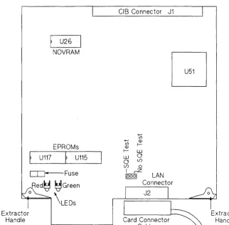
The NOVRAM is an integrated circuit (IC) mounted in a dual in-line package (DIP) at location U26. Refer to Figure 3-1 for approximate location.
The link-level address should be entered on the network map. Some system managers find it helpful to record the link-level address in a system logbook. They use it to promote orderly network changes and additions. All pertinent information is included: the internet addresses, link-level addresses, node names, software directory files, etc. The network map is also part of the logbook.
U26
NOVRAM
EPROMs
U117
f
U115CD--Fuse
Red~ ~Green
o \LEDS
Extractor Handle
CIB Connector J1
...,
(j)
t) ~ Q)
f- W W 0
o (j) (j) 0
I rZ
10001 LAN
Connector
[image:27.614.238.561.72.389.2]J2
SQEJumper
Setting
I
Caution
I
3-4 Installation / Configuration
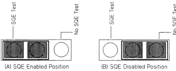
The card contains a three-post SQE (Signal Quality Error) jumper located directly behind the LAN Connector (J2) shown in Figure 3-1. The
placement of the shorting clip will determine if the SQE Test function is
enabled or disabled. The SQE test function is an implementation of the IEEE 802.3 standard.
A jumper shorting clip is installed at the factory in the "SQE TEST"
position which enables the SQE test signal. As you hold the card by the
extractor handles, the shorting clip is positioned on the left side of the three-post jumper, Figure 3-2(A). All IEEE 802.3 installations should have thejumper in this position.
+-'
C/) Q)
f-(A) SOE Enabled Position
U) Q) f-W o (f) o Z +-' C/) Q) f-W o (f) I
o
[image:28.612.242.524.254.368.2](8) SOE Disabled Position
Figure 3-2. SQE Jumper Position
U) Q) f-W o (f)
Some Ethernet 1.0 transceivers do not support SQE Test and therefore,
this function must be disabled on the LAN card. (Refer to the
specifica-tions for the transceiver you are using.)
To disable the SQE test signal, move the jumper shorting clip to the "NO SQE TEST" position, or the right side of the three-post jumper, Figure 3-2(B).
Installation
Installing the LANIC
Card
I
Caution
I
To move the shorting clip to the "NO SQE TEST" position, follow the procedures below.
1. Position the card so the extractor handles are toward you.
2. Remove the shorting clip by lifting it from the jumper posts labeled
"SQETEST".
3. Replace the shorting clip by moving it one jumper post to the right and sliding it down onto the jumper posts labeled "NO SQE TEST" leaving the leftmost pin exposed. See Figure 3-2(B).
The general procedures for installing an interface card are described in your computer system installation manual. You should refer to your systems manual before performing the steps below.
All system power must be off before attempting to install the LANIC card.
1. Log in at the system console and shut down the operating system.
Refer to the HP 9000 System'Administrator's Guide, part number
92453-90004 (furnished with your computer system), for instructions on shutting down the operating system.
2. Turn off power to the host computer system.
3. Install the LANIC card in any authorized slot in the card cage of the computer. See the systems manual for slot dependencies.
4. Ensure that all LAN connections for this node are correct and
LAN Node Connection
Vttni
Ub.)
Installing the Cables
Start-Up and
Verification
3-6 Installation / Configuration
This manual assumes that the LAN cable and cable connectors have been installed. LAN cable and connector installation information for your type of LAN can be found in the following:
• LAN Cable and Accessories Installation Manual (coaxial cable LANs)
• Twisted-pair Cabling Installation Guide (unshielded twisted-pair LANs)
If the node is based on the Ethernet standard, you must ensure that an
Ethernet transceiver has been installed on the coaxial cable.
The MAU/transceiver and cabling to the LANIC card must all conform to the same standard, either IEEE 802.3 or Ethernet. Failure to comply will result in incompatible grounding and an electrical shock hazard.
The same card connector (stub) cable (part number 27125-63009) is used for LAN nodes based on either the IEEE 802.3 standard or the Ethernet Standard. To install the cable, connect the 26-pin connector to the LANIC card. Refer to Table 8-1 for connector cable pin assignment.
For AUI cable connection procedures, refer to the AUI cable connection procedures listed in the Appendix under the type of MAU you have.
Once you are sure that the card and all cables are installed correctly, start up the system by turning on computer power.
The LANIC card is configured into the computer system by HP-UX system administration commands. These are explained in detail in the
HP 9000 System Administrator's Guide, part number 92453-90004.
The LANIC card contains a self-test in EPROM. This self-test is initiated whenever the card is reset (for example, during the system power-up and booting process, or upon command from the LAN diagnostic).
While the self-test is running, a red LED on the LANIC (see Figure 3-1 for approximate location) will light for approximately two seconds,
then go out if the card passes self-test. When the LANIC self-test passes
this point successfully, the test continues by checking the cables in an
External Loopback Test. If the External Loopback test fails, the red LED
Installing the
Software
good, but there is a problem external to the card (for example, the card connector cable, the MAU, the AUI cable)..
After self-test, the green LED on the card will be on continuously to
indicate that power is applied to the MA U.
If the red LED stays on or if the green LED does not come on, refer to
Chapter 6, "Troubleshooting".
Refer to the Installing LAN/9000 Series 800 manual, part number
98194-90009, for information on installing the LAN Link software. If you will be
4
Functional Description
The CIO LAN Link is an implementation of the IEEE 802.3 10 megabit LAN standard and is used to allow HP 9000 Series 800 Computer Systems to communicate with other computer systems over a local area network (LAN). The IEEE 802.3 LAN standard defines a bus utilizing CSMNCD (Carrier Sense Multiple Access with Collision Detect) as the access method.
The link consists of a LAN Interface Controller, interface cables, and Medium Attachment Unit (MAU). The MAU connects to a LAN cable for transmission and reception of signals on the LAN; the interface cables connect the MAU to the LANIC; and the LANIC provides the interface between the LAN and the computer system.
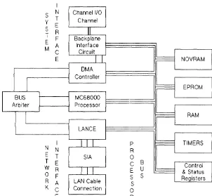
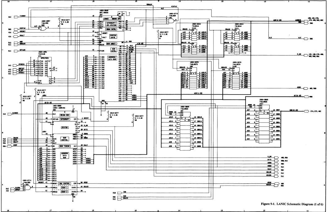
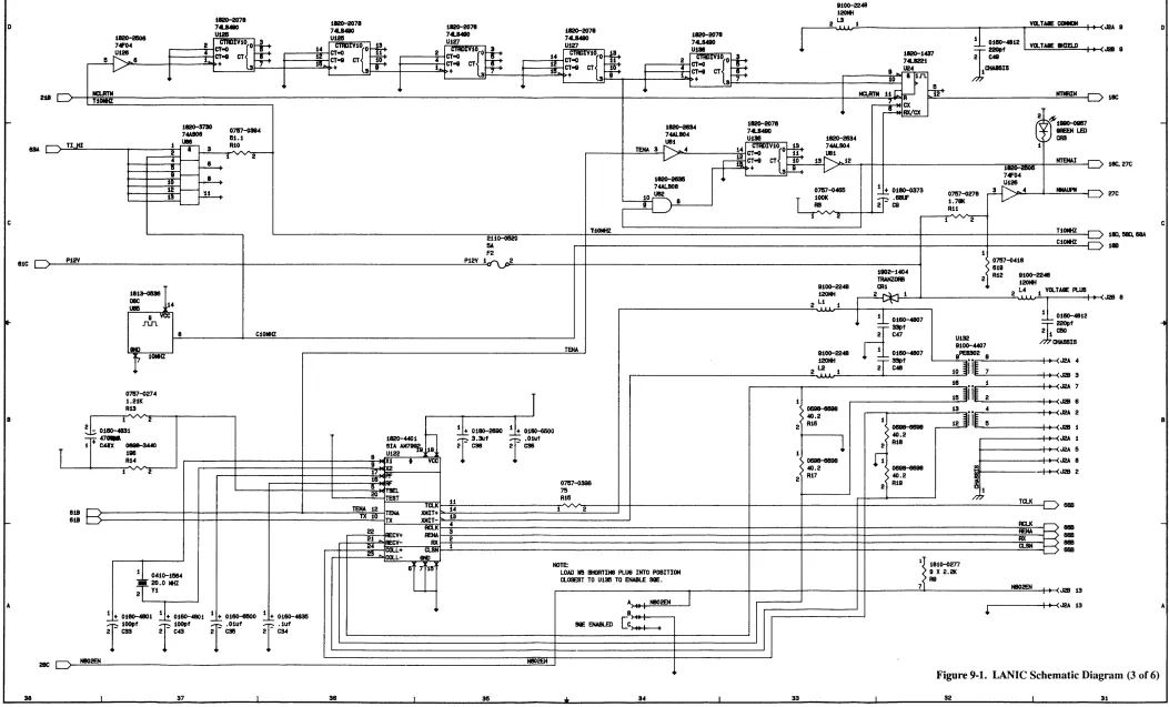
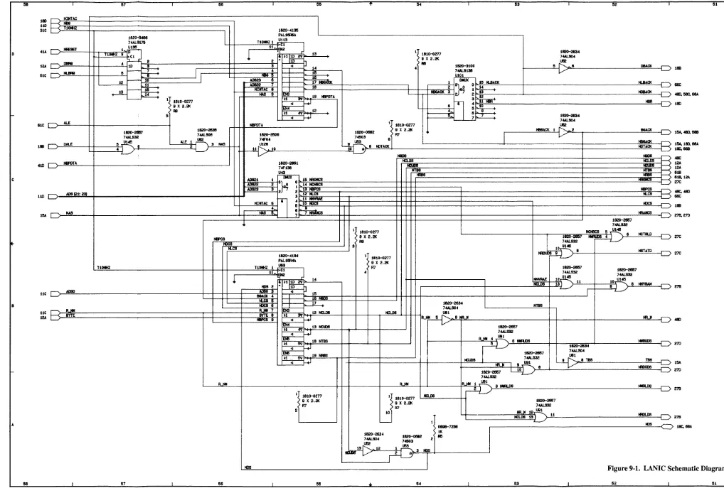
The LANIC is an intelligent DMA channel which communicates with the host system via the Channel I/O Bus (CIB). On the network end of the LANIC, the AUI cable carries bit-serial data and control information to and from the MAU, which attaches directly to the network LAN cable. A functional block diagram of the LANIC is shown in Figure 4-1; schematic diagrams are in Chapter 9.
I
S N
y T
S E
R
T
F
E
M A
C
E
I
Channel 1/0 Channel
P
[image:33.617.226.528.381.660.2]Microprocessor
System Interface
Memory Registers
4-2 Functional Description
An MC68000 microprocessor provides the local intelligence for
control-ling the card's activities. Among other things, it executes the system
channel 110 bus (CIB) protocol and controls the flow of data from the
host computer through the system interface to memory, and through the network interface onto the network cable.
The system interface portion of the card contains all the components that transport data between the CIB and card memory.
The primary components are the AM9516 Direct Memory Access (DMA) Controller and the Backplane Interface Circuit (BIC) chip. The BIC is a custom gate array that provides all control signals needed for interfacing to the CIB. The DMA Controller is used to transfer data quickly between card memory and the CIB with minimal M C68000 control.
Thirty-two Kbytes of EPROM provide program storage of firmware for the M C68000 processor.
Sixty-four Kbytes of static RAM serve as the primary location for data interchange. The RAM stores 32 incoming and eight outgoing data packets, provides the processor with stack and variable space, and provides processor communication paths with the DMA Controller and the LANCE (described below).
A 32-byte NOVRAM (non-volatile static RAM) stores the link-level (node) address of the card and other configuration parameters that must be retained after power-down.
Two timers, using a 10-MHz crystal-controlled reference, are used. One timer generates an interrupt to the MC68000 every 10 milliseconds for timing various software functions. The other timer interrupts the MC68000 whenever the LANCE has been continuously transmitting for more than 4 milliseconds, which exceeds the time required to transmit a legal packet size.
Network Interface
Bus Arbiter
The network interface consists of components that:
• exchange data with memory,
• encode/decode data for transmission/n!ception,
• and transmit/receive data on the cable.
An AM7990 Local Area Network Controlle:r for Ethernet (LANCE) chip
performs the link-level functions for an IEEE 802.3 or Ethernet node. For transmission these include: deference, random back-off and retry,
parallel-to-serial conversion, and CRC (cyclical redundancy check) generation. For reception, these include: alddress filtering,
serial-to-parallel conversion, and CRC checking.
An AM7992 Serial Interface Adapter (SIA) chip performs Manchester
encoding and decoding of the serial data stream. It recovers a receive
clock from the incoming data, and creates a transmit clock via a crystal oscillator (external to the chip). In addition, it interfaces TIL (transis-tor/transistor logic) signals of the LANCE and the differential signals of the attached cable.
Since more than one device can assume control of the processor bus (e.g., DMA Controller, MC68000, LANCE), the bus arbiter watches for bus requests and determines which device will gain bus access. The LANCE is given the highest priority to minimize the number of packets
lost due to unavailable resources. If either the MC68000 or DMA
5
I
Caution
I
LANIC Card and
Connector Cable
Removing the Card
Connector (Stub) Cable
Removal and Replacement
This chapter contains removal and replacement procedures for the CIO LAN Link. These procedures are limited to the LANIC card, the LANIC card connector cable, and the fuse, NOVRAM, and EPROMs on the LANIC card. Refer to the appropriate MAU Appendix for AUI and MA U removal and replacement information.
Before attempting removal of any card or cable from the system, the operating system must be shut down and the system power must be turned ofT. If you leave the power on, you risk electric shock and damage to the computer. Detailed instructions can be found in the HP 9000
System Administrator's Guide, part number 92453-90004.
Some of the components used on the LANIC card are susceptible to damage by static discharge. Refer to the safety considerations informa-tion at the front of this manual before handling the LANIC card. When handling the card, do not touch any components. Hold the card by its edges.
Remove the card connector cable (stub cable) as follows:
1. Shut the operating system down and turn computer system power off.
Removing the
LANICCard
Rep lacing the
LANICCard
I
Note
I
Replacing the
LANIC
Card Connector Cable
5-2 Removal and Replacement
Remove the LANIC card as follows:
1. Shut the operating system down and turn off power to the computer
system.
2. Disconnect the cable from connector J2 on the LANIC card.
3. Remove the card by grasping the extractor handles on each side of the card, and pulling the handles toward you. Once the card starts out of the card cage, pull it all the way out using the extractor handles.
If your are replacing a defective card with an exchange assembly, be sure
to remove the EPROMS from the defective card and install them on the exchange assembly before installing the new card.
Replace the LANIC card as follows:
1. Be sure the operating system is shut down and the power to the com-puter system is off before installing the card.
2. Insert the replacement LANIC card in the same slot from which the
original card was removed. Push on the handles on the outside edges of the card to lock the cardin place. (Follow the installation instruc-tions in Chapter 3 for card installation.)
Replace the LANIC cable as follows:
1. Shut the operating system down and turn power off to the computer system.
2. Connect the 1S-pin D connector end of the cable to the AUI cable
connector. Be sure to slide the clip mechanism so that the connectors are locked together.
Replacing
Components on
the LANIC Card
I
Caution
I
The Fuse
I
Caution
I
NOVRAM
or
EPROM
Replaceable components on the LANIC card are limited to the MAU power fuse, NOVRAM and EPROMs. These components fit into sockets; soldering is not required and may damage the components.
Removal and installation of card components should be performed at a static-free work station.
Order the 125V, 5A fuse from Hewlett-Pa(;kard under part number 2110-0520. Contact your Hewlett-Packard Sales and Support Office.
With the component side of the LANIC ca.rd up, locate the fuse. Figure 3-1 in Chapter 3 shows the approximate fuse location.
Remove the fuse from its socket by gently pulling it free.
Excessive prying or pressure can damage the fuse holder or the card.
Test the fuse for a broken element using an ohmmeter or continuity tester. The fuse should be replaced if an "open" drcuit is indicated. You should always check the fuse first when the green LED is not on when the computer is supplying the LANIC with power.
Installation of a known good fuse simply n~quires inserting it into the
empty fuse socket.
At some point, it may be necessary to replace the NOVRAM or EPROM. For example, NOVRAM or EPROM faults may be revealed by card self-test, or EPROM firmware may require updating.
I
Caution
I
5-4 Removal and Replacement
With the component side of the LANIC card up, locate the NOVRAM or EPROMs. Refer to Figure 3-1 in Chapter 3 for approximate location.
Part numbers and associated socket locations will be as follows:
Component: Type: Location:
1818-4372 EPROM
V115
1818-4373 EPROM
V117
27125-81001 NOVRAM V26
Remove the component from its socket, without damaging the socket. An IC removal tool reduces any chance of ruining the chip, socket, or board.
Excessive prying and pressure can damage the socket and component; use great care during removal.
When installing the replacement component, note the half-circle notch located on one end. The notch shows the orientation of the Ie, and must be matched with a similar notch on the empty socket. Ensure that the Ie
pins are aligned with the socket receptacles. It may be necessary to adjust
the pins (bow them inward or outward) for proper alignment. Gently
press the Ie into place to properly seat the pins. If pressure is not applied
uniformly, the pins on one side or the other may fold and collapse without
properly mating in their sockets. (Note: If this happens, remove the Ie,
straighten the pins, and try again. If extensive damage occurred, you may
6
Safety
Considerations
i'E'U".t·j
I
Caution
I
Troubleshooting
Troubleshooting
Major hardware subassemblies of the link are categorized as field
replaceable units (FRUs); troubleshooting is used to identify a defective
FRU. The link includes the LAN interfac,e controller (LANIC) card, the
LANIC card connector cable, and the applicable Medium Attachment Unit. (Refer to the appropriate Appendix for additional MAU information.)
This chapter summarizes the diagnostic used to identify problems on the link in order to isolate a defective FR U.
Before attempting to remove or replace any card or cable in the system, follow the power down instructions in the system manual. Failure to turn
ott the power creates an electrical shock bazard and may damal~e the
card or the computer.
Some of the components used on the LANIC card are susceptible to damage by static discharge. Refer to the safety considerations at the front of this manual before handling the LANIC card. When handling the card,
do not touch any components. Hold the c:ard by its extractors o:~ by its
edges.
Maintenance
Preventive
Maintenance
Maintenance Aids
6-2 Troubleshooting
There are no specific preventive measures for the LANIC. When the host
computer scheduled maintenance is done, it is a good idea to:
• Check the card connector cable (stub cable) for visible damage and
wear.
• Check the MAU and the AUI cable for damage and wear.
• Check that the LANIC is properly seated in the card cage.
To test and troubleshoot the LANIC, you will need one of the following:
• HP 92257B MAU Test Fixture (used with the HP 30241A MAU)
• HP 92257Q ThinMAU Test Fixture (used with the HP 28641A ThinMAU)
• HP 5061-4977 Loopback Connector (used with the HP 28664A
Twisted-pair MAU)
It is helpful to have a set of known good spares to exchange for suspected
Local Area
Network Device
Adapter
Diagnostic
LANDAD Capabilities
Minimum
Configuration
Hardware
The Local Area Network Device Adapter Diagnostic (LANDAD) is the part of the Online Diagnostic Subsystem used to detect a failure in one or more of the LANIC FRUs.
This section gives a brief description of LAND AD. For more detailed information refer to the Online Diagnostic Subsystem Manual, Volume 1.
LANDADcan:
• Identify the product type and node (link-level) address of the LANIC.
• Report the status of the LANI C.
• Report the link statistics of the LANIC.
• Reset the LANIC.
• Initiate self-test on the LANIC.
• Execute a local or externalloopback.
• Send TEST or XID (exchange identifi.cation) packets to a remote node and interpret the results.
• Perform tests that check AUI cable and MAU operation.
If you are familiar with LANDAD and merely want to run the program, skip this introduction and go to the "Running LANDAD" section.
LANDAD Operational
Modes
6-4 Troubleshooting
Before you run LANDAD, make sure the LAN is set up for the test
sections you will run. Many sections can be run without affecting the rest
of the network, but some go out onto the medium and read or write either to the card you are testing or to other nodes. LANDAD has two different modes as described below:
• Normal Mode - LANDAD tests which use this mode will not destroy
data on that LANIe, other Network Nodes on the LAN, or other
devices on the system. An example of a normal mode test is a request
for link level statistics. The sections that run in normal mode are: 1, 3, 4, 6, 7, 9, and 10.
• Destructive Mode - Tests using this mode will destroy data on the
LANIe
and affect other users on the system. Jfyou plan to run tests in this mode, be sure that you are the only system user before you begin. An example of a destructive mode test is self-test, which willbring the LANIe off-line and destroy any data transfer in process.
Sections which run in destructive mode are: 2, 5, 8, 11, and 12.
Remember, to run a destructive test in LANDAD, you must use the
system console or a terminal attached to a different
LANIe
from the oneDescription of
LANDAD Sections
Section 1 - More Help
The LANDAD sections and steps are summarized below.
Section Diagnostic Function
Number
1. More Help
2. Reset
3. Identify
4. Local Loopback (to LANIC and back)
5. Self-test
6. Status
7. Link Statistics
Step 71 - Read and decode link statistics Step 72 - Reset link statistics
8. External Loopback
9. Remote Node Test
10. Remote XID Test
11. AUI Cable Fault Isolation Test
12. Offline MAU Test
Step 121 - Two-Terminator Test Step 122 - One-Terminator Teslt
More Help is an interactive section which allows you to obtain more information about a particular section or step than is given when typing help at the Online Diagnostic Subsystem prompt. This section provides a
means for all users from any terminal to obtain additional information
Section 2 - Reset
I
Note
I
Section 3 - Identify
Section 4 - Local
Loopback
Section 5 - Self-test
I
Note
I
Section 6 - Status
6-6 Troubleshooting
Reset causes a reset of the LANIC to its power-on state. All pertinent data needed by the LANIC to operate properly will then be downloaded
to the LANIC. If, after a reset of a LANIC that is offline due to bad
hardware, the LANIC indicates that it passed its self-test, the LANIC will be put into the online state.
It is better to do a self-test command (section 5) to bring the LANIC back
online because it checks status of the LANIC card and displays what has failed if the LANIC contains a fault.
Identify causes a Status command to be issued to the LANIC. This
command then decodes the information obtained and displays it in descriptive terms. This section can be used to determine what the LANIC hardware and frrmware datecodes are. It is also useful in that if it
executes successfully, the path from the diagnostic to the LANIC is at least partially functional.
Local Loopback will test the data path from the diagnostic to the card and back. A self-addressed frame is transmitted and a byte-for-byte
comparison of the transmitted data is compared with the returned data to
determine if it has been corrupted. Since the LANIC only loops back the
frame if the transmission onto the network medium is successful, this test
also checks all components from the network medium to the driver. If the
transmission is not successful, the suspected problem is returned.
Self-test tells the LANIC to perform a hardware self-test. If the returned
self-test status is abnormal, messages indicating the problem are dis-played.Since self test brings the card offline and aborts all current
infor-mation transfers, it should only be done when absolutely necessary. If
self-test passes, it will put the LANIC into the online state. If message
LANDADW ARN 6005 is ever displayed, selftest should be run to first determine if the LANIC is functional, and if it is, to put the card back online.
If this section completes successfully, it will put the LANIC into the online
state, even if it is in the offline state when the section is called.
Section 7 - Link Statistics
Link Statistics displays the link statistics stored by the LANIe. It also allows you to reset these link statistics.This function has two steps: Step 71 is the default step. It reads link statistics from the LANle and decodes them. To invoke this step, enter:
DUI > run landad <pdev=X.Y section:7 < RETURN>
Where "X" is the system dependent channel address, and "Y" is the slot number. For more details, refer to the "Hardware Addressing"
section of your System Administrator's Manual.
The second function is the reset statistks function, step 72. This function is disruptive since it modifies data on the LANle. Since step 72 is not a default step, you must enter the following:
DUI > runlandadpdev=X.Ysection=7 st.ep=72 <RETURN>
Step 71 - Read and Display Link Statistics
This step requests link level statistics from the LANle and displays the
statistics.
Step 72 - Reset Link Statistics
Section 8 - External
Loopback
I
Note
I
I
Note
I
6-8 Troubleshooting
External Loopback first takes the card offline and then tells the LANIC to perform an externalloopback test. This test transmits and receives a
frame off the network cable. If this test passes, the following hardware
appears to be functional.
1. This Network Cable Segment. (Use an ohmmeterrrDR to verify.)
ThickMAUs (30241-60102) and ThinMAUs (28641-60004) with date code
A-2735, are unable to detect network cable shorts. To determine if the
cable is connected properly, it may be tested with an ohmmeterrrDR.
2. Both 50 ohm terminators.
3. The MAU connection to the LAN.
4. TheMAU.
5. The AUI cable(s).
6. The card connector cable.
7. TheLANIC.
If this section completes successfully, it will put the LANIGinto the online
Section 9 - Remote Node
Test
I
Note
I
I
Note
I
Section 10 - Remote XlD
Remote Node Test checks the ability of this node to bounce a packet off another node connected to the same physical network. When there are repeaters in the network, the packet is bounced off a node in the same logical network. This is useful for two reasons: First, it shows the node can communicate with a remote node. Second, it can point to upper level software problems. If a frame can be bounc:ed off another node using the diagnostic, but normal NS communications do not work, the hardware is working, so the problem is in the upper level software.
This section sends an IEEE 802.2 test fram(~. This test frame can be any length from 60 bytes (a minimum 802.3 frame) to 1514 bytes (a maximum length 802.3 frame). The default is 500 byte:s. When a test response frame
is received from the remote station, its length is checked for being either a minimum size frame or for being the specified length -0/
+
1. If the response frame is not a minimum size fram(~, then the data is checked against the data sent. If it is not the same, then the test frame part of the test fails.This section will allow communication only to individual network addresses. If you input a broadcast or multicast address as a response to the Remote Node Address prompt, an error message will be issued and you will be prompted again for a valid remote node address.
The remote node MUST be capable of responding to IEEE 802.2 test frames, and that node must be in a state to answer those frames. For example, most systems must have the °LANIC device driver installed and operating before test frames will be answerl~d.
Part of what this section tests is the receive threshold of the MA Us at the two nodes involved in the test. The worst e<ilSe for this is when the two nodes are the maximum 500 metres (185 metres for ThinLAN) apart. Therefore, the test results are most signifi~mt if you attempt to bounce frames off the most distant node.
Section 11 - AUI Cable
Fault Isolation
I
Note
I
I
Note
I
6-10 Troubleshooting
AUI Cable Fault Isolation isolates a broken cable in the A VI cable segment. This is done by repeatedly sending extemalloopback frames
and checking to see if the frame loopback was successful.
To run this section connect a terminated loopback fIXture to the end of the stub cable and start the text. Next, disconnect the loopback hood at the stub cable, reconnect the stub cable to the AVI cable, and connect the
loopback fIXture to the other end of the AVI cable. If there are multiple
A VI cables, continue doing this until all the A VI segments are tested.
If the A VI cable segment passed the test, a "P" is printed. If it did not . pass, one of the following fail codes will appear on the screen.
Fail Code Description
L Loss of carrier error
possible broken AVI cable
R Retry fault
possible bad loopback hood
I Infmite deferral
possible bad loopback hood
As you disconnct and reconnect the loopback test fIXture to the different
AVI segments, the Loss of Carrier error code (L) will print 0 the screen
when the cable is disconnected.
The last thing this section does is reset the LANIC. If the reset is
Section 12 - Omine MAU
Test
I
Note
I
I
Note
I
Omine MAU Test provides a way to verify that a MAU is operating properly. In order to run this test, the MAU should be taken off the network cable and the terminated loopback test fIxture for your MAU should be attached to it. (See the "Test Equipment and Special Tool" section in Chapter 1 for test fIXture part numbers.) You then run the fIrst step of the test (Step 121).
1. Step 121 - Two-terminator Test
This step expects that the loopback hood has both 50-ohm terminators attached. The test sends out a group of eight external loopback frames to the MA U. These frames should be transmitted and received successfully.
2. Step 122 - One-terminator Test
Step 122 of this section asks you to take one of the 50-ohm
terminators off the loopback hood. It then sends eight external
loopback frames to the MA U. These should all fail, indicating that
Retry Errors have occurred. This step uses the same activity indicators as the AUI Fault Isolation Section.
For detailed instructions to run this test, n:fer to the Online Diagnostic
Subsystem Manual Volume 1 .
This test is not applicable for the Twisted-pair MAU.
The last thing that this section does is reset the LANIC. If the reset is successful, the LANI C is put into the online state, even if it is in the offline state when the section is called. A subtle side effect also occurs after this test is run. Since the last externalloopback frame sent out when running this test fails due to retry faults when using a healthy MAU, any additional status requests (section 3,4,6,7,9,10) will indicate that a retry fault
Running
LANDAD
I
Note
I
6-12 Troubleshooting
LANDAD is accessed via the Online Diagnostic Subsystem. To bring up the Online Diagnostic Subsystem enter the following command to the HP-VX system prompt:
#/usr/dl~~Il6;n/sYsqi.;lg < RETURN >
The system responds with the following prompt indicating that access has been gained to the Online Diagnostic V ser Interface CD VI).
DUI>
To run the diagnostic, enter:
DU I
»>rl.ir(laridadPdey..,X.Y>
< RETURN>"X" is the system dependent channel address, and "Y" is the slot number of the LANIC card.
If there is an error, such as failure to fmd a LANIC as the specified dev-ice, the LANDAD diagnostic will terminate and the Online Diagnostic Subsystem prints an error message.
Since LANDAD is a subset of the Online Diagnostic Subsystem, any time you terminate LANDAD operation, control returns to the Online Diag-nostic Subsystem. To do so, enter "exit" to terminate the diagDiag-nostic at any LANDAD prompt. The frrst letter "E", or the entire word "EXIT", in either upper or lower case, will terminate LANDAD execution. If you exit in this manner, the following message is displayed:
LANDAD Prompt
>A·
< RETURN>Any time the program is executing, you may enter an interrupt character (the default is CONTROL C) to halt operation. When it detects the break, one of two things will occur, depending on whether the diagnostic
can suspend the operation. If so, it will print the following message and
return control to the Online Diagnostic Subsystem.
LANDAD suspended per user request ...
You may then either resume or abort the diagnostic. If the diagnostic has
progressed to a point where it cannot suspc::nd, the following message will be printed:
Unab le to suspend in current state. Abort i ngr LANDAD ...
Example of a Diagnostic
Session
6-14 Troubleshooting
The following example illustrates running sections 1, 2, 3, 4, and 7 of the di-agnostic. User input is shown in this t,ypeface.Note that section I--More Help, pauses after printing the first paragraph. If you need informa-tion about other secinforma-tions, enter the appropriate secinforma-tion number. If you want to continue to section 2, merely press < RETURN> (see the ex-ample below).
login: root < RETURN>
Password: XXXXXX <RETURN> (see your system manager) Welcome to HP-UX. [Release X.X]
WARNING: YOU ARE SUPERUSER ! !
#/usr/diag/bin/sysdiag < RETURN>
************************************************************************
****** ******
****** ONLINE DIAGNOSTIC SUBSYSTEM ******
****** ******
****** (c) Hewlett-Packard Co. 198X ******
****** All Rights Reserved. ******
****** Version X.XX.XX ******
****** ******
************************************************************************
DU I > rLJJ11ar1dadpd~'1::X. Y>secti()r1~ L 2,3,4,7 <RETURN>
************************************************************************ ******
****** ****** ****** ****** ****** ******
LANDAD LAN Device Adapter Diagnostic
(c) Hewlett-Packard Co. 198X All Rights Reserved.
Version X.XX.X.XX
****** ****** ****** ****** ****** ****** ****** ************************************************************************
I
Note
I
Sect ion 1 -- More He lp
This Section allows you to get more information on all of the sections [1. .12] of this diagnostic. Please indicate the number of the section for which you need more informat ion. Entering a <return> to the prompt exits this section.
More He 1 p » < RETURN> End of Sect ion 1 -- More He lp Sect ion 2 -- Reset
End of Sect ion 2 -- Reset
Sect ion 3 -- Ident i fy
CIO card 10 byte = $06 (LANIC) Hardware Datecode
=
2512 Hardware Revcode = 4 Firmware Datecode=
2620 CIO Firmware 10 = 1NOVRAM (Permanent) stat i on address = $08-00-09-00-3E -E9 RAM (Currently Active) station address = $0,8-00-09-00-3E-E9 End of Sect ion 3 -- Ident ify
Sect ion 4 -- Loca 1 Loopback
Logging SSAP with driver ... Sending data to lANIC ... Receiving data from lANIC ...
A frame has been sucessfully transmittE~d onto the network media Path to lANIC is functional.
End of Sect ion 4 -- loca 1 loopback
6-16 Troubleshooting
Section 7 -- Link Statistics
Step 71 - Read and Display Link Statistics
Link level statistics have been read successfully.
Transmit Statistics
TOTAL frames transmitted without error First time transmits
Deferred transmits One collision transmits
More than one collision transmits TOTAL frames NOT transmitted
Retry error 0 Late collision Loss of carrier during transmit No heartbeat detected after transmission No free transmit buffers
TDR of last retry error LANCE restarts
Receive Statistics
TOTAL frames received without error Frames rejected by address filter Frames rejected due to CRC errors Frames rejected due to alignment errors Frames rejected due to oversize length LANCE indicated one or more frames lost No free receive buffers
End of Step 71 - Read and Display Link Statistics
End of Section 7 -- Link Statistics
landad terminated (pid 454). Exit status O. DUI > >E < RETURN >
o
o
o
o o
o
o
o
o
o
o
o
o
o
o
7
I
Note
I
Ordering
Information
Field Replaceable
Units
Replaceable Part!s
This chapter contains information on repla.ceable parts for the LANIC.
Customer repair, including replacing parts on the LANIC card, is not recommended by Hewlett-Packard. Customers who perform component level replacement will invalidate the 9O-day warranty and render the card ineligible for exchange.
To order replacement or exchange PRUs, or to obtain information on the parts, address the order or inquiry to the nearest Hewlett-Packard Sales and Support Office.
To order a part, specify the following information:
1. Identification of the CIO LAN Link iIlLterface or part.
2. Check digit (CD).
3. Description and function of the part.
4. Quantity required
Exchange Assemblies
I
Note
I
Component Parts
7-2 Replaceable Parts
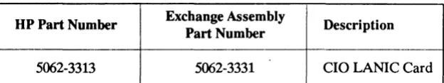
[image:58.612.233.545.132.190.2]Table 7-11ists the current assembly which qualifies for the HP exchange program, that is, a defective card can be exchanged for a refurbished card.
Table '·1. Exchange Assembly Part Number
UP Part Number Exchange Assembly Description
Part Number
5062-3313 5062-3331 CIO LANIC Card
If the LANIC card is to be returned to Hewlett-Packard for service or repair, remove the frrmware EPROMS (VIIS and VI17), attach a tag identifying the owner and indicate the type of service or repair required. Include the part number and date code of the card.
The frrmware EPROMs must be removed from the LANIC card before it is returned for service or repair. The EPROMs are NOT included with the exchange assembly.
Pack the card in the original factory packaging material if available. If the original packaging material is not available, wrap the card in suitable cushioning material (Air Cap TH-240 Cushioning or equivalent) and place the card in a corrugated carton (200-pound test material). Seal the carton securely and mark it FRAGILE to ensure careful handling.
[image:58.612.241.509.506.668.2]There are only a few LANIC card components which qualify as field replaceable units. These parts are available through any Hewlett-Packard Sales and Support Office. Table 7-2 lists the components along with all the necessary information to order these parts.
Table '·2. Replaceable Component Parts
Reference UP Part C Description
Designation Number D
F2 2110-0520 6 Fuse
U26 27125-81001 3 NOVRAM
VIIS 1818-4372 3 EPROM
New Assemblies
Those FRUs that cannot be exchanged can be ordered as new parts. Table 7-3 lists all items which qualify as new assemblies.Table 7-3. New Assembly Part Numbers
UP Part Number Description
27125-63009 LANIC Card Connector Cable
28641-60004 ThinMAU Assembly (without BNC "T")
28664-60001 Twisted-pair MAU assembly
30241-60102 ThickMAU Assembly (without tap)
0362-0819 ThickMAU Coaxial Tap
1250-0781 ThinMAU BNC "T" Connector
5061-4977 Loopback Conn.ector
8
Technical Manual
Reference
Reference
This chapter contains a list of other technkal manuals and related documents which will be of assistance to you, and a glossary of terms.
Other technical manuals which might be required are listed below:
LAN/9000 Series 800 Manuals
Installing IAN/9000 Series BOO
Troubleshooting IAN, NS, ARPA Services/9000 Series BOO
IAN/9000 Series BOO LIA Programmer's Guide
IAN/9000 Series BOO Berkeley IPC Programmer's Guide
HP 9000 NetIPC Programmer's Guide
IAN Reference Pages
HP 9000 Series BOO Networking Overview: IAN, x'25, NS, ARPA andNFS
NS Cross-System Network Manager Reference Manual
This Manual
98194-90009
98194-90010
98194-90006
98194-90003
98194-90002
98194-90004
50980-90021
5958-8564
8-2 Reference
NS/9000 Series 800 Service Manuals
Installing Network Services (NS)/9000 Series 800
Using Network Services (NS )/9000 Series 800
Network Services Reference Pages
NS Cross-System NFT Reference Manual
98194-80008
50980-90040
50951-90031
5958-8563
ARPA Services/9000 Series 800 Manuals
Installing ARPA Services/9000 Series 800
Using ARPA Services/9000 Series 800
ARPA/Berkeley Services Reference Pages
NFS Services/800 Mauals
Using and Administering NFS Services/800
Programming and Protocols for NFS Services/800
NFS Services Reference Pages
MAUManuals
ThinMAU Installation Manual
Twisted-pair MAU Installation Guide
98194-90007
50980-90001
50952-90032
50970-90000
50970-90010
50970-90030
28641-90001
Other Manuals
Online Diagnostic Subsystem Manual, Volume 1
Cable and Accessories Installation Manual
HP Site Wire Twisted-pair Installa-tion Guide
HP StarLAN 10 Hardware Troubleshooting Guide
HP 9000 System Administrator's Guide
Installing and Updating HP-UX
09740-64013
5955-7680
5959-2208
5959-2258
92453-90004
Table 8-1. LANIC Card Connector Cable Pin Assignment
26-pin Card Signal IS-pin
Connector Name Connector
Pin Number Pin Number
1A Chassis Ground 1,4
IB Collision (-) 9
2A Cossision ( + ) 2
2B Chassis Ground 1,4
3A
3B Transmit (-) 10
4A Transmit ( + ) 3
4B Drain
SA Chassis Ground 1,4
SB 6A
6B Receive (-) 12
7A Receive (+) S
7B
8A Chassis Ground 1,4
8B Power 13
9A Power Return 6
9B lOA lOB 11A 11B 12A 12B 13A 13B Plate GND ContactGND
Foil shield on each twisted pair.
Glossary of Terms
ASCII
AUI
Baud
bps
Broadcast
Card
CCITI
The following terms are dermed as they ar(~ used in Hewlett-Packard
computer networking products manuals. The glossary is an all-inclusive list of terms used in a broad range of technical manuals and therefore some of the terms dermed might not be used in this manual.
American Standard Code for Information Interchange, a data communica-tions code set defining letters, characters and machine or control com-mands (such as end of line, or line feed). ASCII uses seven bits to define these characters, and duplicate them (as for a second font) or as a parity check bit.
Attachment Unit Interface. The cable that connects the card (and card connector cable) to the MAU.
Unit of signaling speed expressed as the number of signal event changes (as phase, frequency or amplitude) per second. As a function of both the modulation scheme and the transmission carrier frequency, it is rarely the same as "bits per second". When two bits are combined to form a signal unit, the baud rate is half the bps (the signal unit is call a "digit"), and has four levels, or states.
Bits per second, the speed of data transmission over a communications channel.
A communication method of sending a message to all devices on a link simultaneously.
The Printed Circuit Assembly (see PCA).
Comite Consultatif International Telephonique et Telegra Telephique,
CRC
CSMNCD
Cyclic Redundancy Check
DIP
Distributed System
DMA
Download
Driver
DS
8-6 Reference
Cyclic Redundancy Check. A method of using a polynomial to perform error checking. The polynomial is an algebraic function used to generate a constant from the message bit pattern. This constant, derived and accumulated in both the transmitter and receiver, is used to divide the b